
Related Manuals for Siemens SDV7-AR


Summary of Contents for Siemens SDV7-AR
- Page 1 Instruction manual Type SDV7-AR arc-resistant distribution circuit breaker Installation operation maintenance E50001-F710-K379-V5-4A00 www.usa.siemens.com/sdv7...
- Page 2 Is trained in rendering first aid. purchased. Siemens reserves the right to make changes in the specifications shown herein or to make improvements at any Further, a qualified person shall also be familiar with the proper use time without notice or obligation.
-
Page 3: Table Of Contents
Siemens Industry, Inc. The warranty contained in the contract between 35 – 42 Maintenance the parties is the sole warranty of Siemens Industry, Inc. Any statements contained herein Maintenance and troubleshooting 43 – 47 do not create new warranties or modify the existing warranty. - Page 4 Arc flash hazard and hazardous voltages. Will cause death, serious injury or property damage. Always de-energize and ground the equipment before maintenance. Read and understand this instruction manual before using equipment. Maintenance should be performed only by qualified personnel. The use of unauthorized parts in the repair of the equipment or tampering by unqualified personnel will result in dangerous conditions which will cause death, severe injury or equipment damage.
-
Page 5: Introduction
For medium-voltage customer service issues, fabrication by Siemens. contact Siemens at +1 (800) 347-6659 or +1 The purpose of this instruction manual is to (919) 365-2200 outside the U.S. assist the user in developing safe and efficient procedures for the installation, maintenance and use of the equipment. -
Page 6: General Description
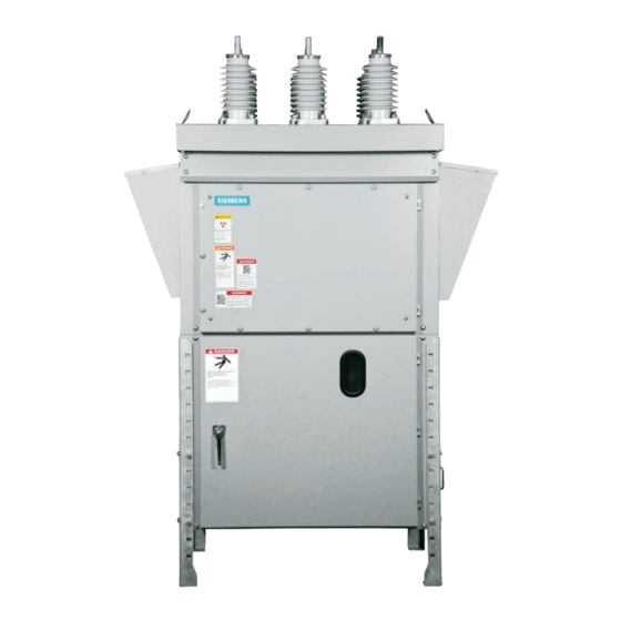
2B accessibility rating per ANSI/IEEE C37.20.7. Figure 1: Typical type SDV7-AR distribution circuit breaker Scope Introduction These instructions cover the installation, Siemens type SDV7-AR distribution circuit... - Page 7 Siemens may cause the warranty to be void. during an internal arcing fault event: This instruction manual applies to the type 1.
-
Page 8: Receiving, Handling And Storage
SDV7-AR delivery receipt. distribution circuit breaker must be handled 2. Make immediate inspection for visible carefully when unloading. - Page 9 If inspection their agent, Siemens cannot be held liable for concealed damage is not practical at for repairs. Siemens will not be held liable the time the carrier’s inspector is for repairs in any case where repair work...
- Page 10 Forklift trucks may be used prior to removal Storage of wooden skids. Verify the forklift blades When it is necessary to store a type SDV7-AR pass completely through the wooden skid distribution circuit breaker in an area under the circuit breaker.
-
Page 11: Installation
Installation Preparation for installation The legs must be installed and turned inward, Prior to installation of the type SDV7-AR so that the two sides of the each leg are distribution circuit breaker, careful design, adjacent to the enclosure sides and the hole... - Page 12 Figure 3: Outline drawing 2-4-6 1-3-5 Note 1: Shown High-voltage with optional compartment cross-bracing for high-seismic loading, and with legs installed at maximum height 28” Operator Relay and (711 mm). compartment control Ground compartment Note 2: Unit pads on must be diagonally installed with opposite...
- Page 13 Figure 4: Anchoring type SDV7-AR distribution circuit breaker Dimensions in inches (mm) 15.5 kV 27.6 kV 38.0 kV 15.5 kV Item 1,200 A- 1,200 A- 1,200 A- 3,000 A 2,000 A 2,000 A 2,500 A 47.1 (1,196) 56.5 (1,435) 56.5 (1,435) 67.8 (1,722)
-
Page 14: Electrical Connections
National Electric Safety Code® for ground terminal points for each circuit. connection standards. Connection diagrams are provided with each type SDV7-AR distribution circuit breaker and will be found in the pocket inside the relay and control compartment door. -
Page 15: Instrument Transformers
Figure 5: Type SDV7-AR distribution circuit Phase barriers are provided on all 27.6 kV and breaker with interphase barriers and bushing 38 kV class type SDV7-AR distribution circuit current transformers installed in primary breakers as shown in Type SDV7-AR compartment on page 16 illustrates bushing... - Page 16 Figure 5: Type SDV7-AR distribution circuit breaker with interphase barriers and bushing current transformers installed in primary compartment 2-4-6 1-3-5 Bushings Vacuum Bushings 2-4-6 interrupter 1-3-5 X1 X2 X3 X4 X5 X1 X2 X3 X4 X5 X5 X4 X3 X2 X1...
-
Page 17: Installation Of Type Sdv7-Se Distribution Circuit Breaker With Stored-Energy Operator
Installation of type SDV7-SE circuit breaker with stored- energy operator Hazardous voltages and high speed moving parts. Will cause death, serious injury or property damage. Read instruction manuals, observe safety instructions and use qualified personnel. Introduction De-energizing control power in a power This section provides a description of the circuit breaker inspections, checks and tests to perform on... - Page 18 Opening the knife switch de-energizes control power to the circuit breaker. In some circuit breakers, pullout type fuse holders or molded-case circuit breakers are used in lieu of knife switches. Removal of the fuse holder or opening the molded-case circuit breaker accomplishes the same result: control power is disconnected.
- Page 19 Figure 6: Relay and control and operator compartments for type SDV7-SE-AR circuit breaker with stored-energy operator 2-4-6 1-3-5 Item Description External manual trip Control disconnect device Relay and control compartment Operator compartment Push-to-trip pushbutton Push-to-close pushbutton Operations counter OPEN/CLOSE indicator CHARGED/DISCHARGED indicator Opening for manual charging Reset mechanism for external manual trip...
- Page 20 Manual spring charging check 2. Open control power circuit by opening 1. Insert the manual spring charging crank knife switch shown in Figure 6: Relay and into the manual charge socket as shown control and operator compartments for in Figure 6: Relay and control and type SDV7-SE-AR circuit breaker with operator compartments for type SDV7-SE- stored-energy operator on page 19.
- Page 21 8. Repeat the spring discharge check 13. All filters in vent areas are clean and free presented on page 18. of shipping or construction material. 9. Verify the springs are DISCHARGED and 14. Arc-exhaust vents correctly secured, the circuit breaker primary contacts are undamaged, and free to open in the OPEN by observing the indicator event of an internal arcing fault.
- Page 22 High potential tests employ hazardous voltages. Will cause death or serious injury. Follow safe procedures, exclude unnecessary personnel and use safety barriers. Keep away from circuit breaker during application of test voltages. After test completion, ground both ends and the middle ring (if visible) of the vacuum interrupter to dissipate any static charges.
- Page 23 Table 2: High-potential test voltages Rated Rated power-frequency Field-test voltage maximum voltage withstand kV (rms) kV (rms) kV (rms) kV dc 15.5 37.5 27.6 38.0 Note: The dc test voltage is given as a 3. Charge the closing springs manually and reference only.
- Page 24 2. Check torque of the bolts that secure the roof bushings to the top plate of the type SDV7-AR distribution circuit breaker. Torque should be in the range of 20-25 ft- lbs (27-34 Nm). 3. Connect primary incoming power source to circuit breaker.
- Page 25 Installation of type SDV7-MA circuit breaker with magnetic-actuator operator Hazardous voltages and high speed moving parts. Will cause death, serious injury or property damage. Read instruction manuals, observe safety instructions and use qualified personnel. Introduction De-energizing control power in a power This section provides a description of the circuit breaker inspections, checks and tests to perform on...
- Page 26 Opening the knife switch de- NOTICE energizes control power to the circuit breaker. In some circuit Capacitor discharge plug (105.2) breakers, pullout type fuse holders or molded-case circuit Disconnect control power prior to removing or replacing the capacitor discharge plug. Refer to Figure 7. breakers are used in lieu of To discharge capacitors: knife switches.
- Page 27 Discharging capacitors Automatic capacitor charging After control power has been removed, The controller board (105.0) executes a self- discharge stored energy from the capacitors test of the capacitors (106.2) and checks the (refer to Figure 7: Operator controls and status of the capacitors (106.2). This self-test discharging capacitors.
- Page 28 As-found and vacuum-integrity check 3. In step 2, when the close pushbutton was tests pressed, the circuit breaker should have Perform and record the results of both the as- closed, and the capacitors should have found insulation test and the vacuum- recharged automatically.
- Page 29 c) Press black Close pushbutton (53.0). discharging capacitors on page 26) to close the circuit breaker. d) Verify main contact status indicator shows CLOSED. 3. Use the manual opening handle on the right side of the enclosure (refer to Figure e) Press red Open pushbutton (54.0) 8: Relay and control and operator again.
- Page 30 Figure 8: Relay and control and operator compartments for type SDV7-MA-AR circuit breaker with magnetic-actuator operator 2-4-6 1-3-5 Item Description External manual trip Control disconnect device Relay and control compartment closed Relay and control compartment open Operator compartment Push-to-trip pushbutton Push-to-close pushbutton Operations counter OPEN/CLOSE indicator...
- Page 31 Inspection NOTICE Check the following points: 1. Make a final mechanical inspection of the Shipping bracing and tag between phase barriers circuit breaker. Verify the contacts are in (on units so equipped) may damage circuit the OPEN position. breaker. 2. Confirm the circuit breaker is properly set May result in damage to equipment.
- Page 32 High-potential tests employ hazardous voltages. Will cause death or serious injury. Follow safe procedures, exclude unnecessary personnel and use safety barriers. Keep away from circuit breaker during application of test voltages. After test completion, ground both ends and the middle ring (if visible) of the vacuum interrupter to dissipate any static charges.
- Page 33 Table 3: High-potential test voltages Rated Rated power-frequency Field-test voltage maximum voltage withstand kV (rms) kV (rms) kV (rms) kV dc 15.5 37.5 27.6 38.0 Note: The dc test voltage is given as a 3. Energize the control circuits. For reference only.
- Page 34 2. Check torque of the bolts that secure the roof bushings to the top plate of the type SDV7-AR distribution circuit breaker. Torque should be in the range of 20-25 ft- lbs (27-34 Nm). 3. Connect primary incoming power source to circuit breaker.
-
Page 35: Maintenance
Periodic inspections and maintenance are well as others who might be exposed to essential to obtain safe and reliable operation hazards associated with maintenance of the type SDV7-AR distribution circuit activities, the safety-related work practices of breaker. NFPA 70E (especially chapter 1) should... - Page 36 Recommended hand tools SAE (U.S. customary): Type SDV7-AR distribution circuit breakers Socket and open-end wrenches: uses both standard SAE (U.S. customary) and 5/16, 3/8, 7/16, 1/2, 9/16, 11/16, 3/4 and metric fasteners. Metric fasteners are used for 7/8”; 7, 10, 13, 17 and 19 mm the vacuum interrupters and in the vacuum interrupter/operator module.
- Page 37 Vacuum-integrity check not covered sufficiently for the Purchaser’s High-potential test purposes, the matter should be referred to Siemens at +1 (800) 347-6659 or Insulation test +1 (919) 365-2200 outside the U.S. Contact-resistance test Inspection and cleaning of circuit breaker insulation...
- Page 38 De-energize the circuit breaker Discharging capacitors Prior to performing any inspection or After control power has been removed, maintenance checks, the circuit breaker must discharge stored energy from the capacitors be de-energized and grounded. Principal (refer to Figure 7: Operator controls and steps are outlined below for information and discharging capacitors on page 26).
- Page 39 Use anti-seize compound (Loctite* 77164 or 77124 nickel anti-seize) on the threads of Figure 9: Side view of type SDV7-AR distribution circuit breaker the roof studs to facilitate future removal of All of these components must be cleaned and a bushing should it become necessary.
- Page 40 High-potential test voltages If dc high-potential tests are used, note the *Megger is a registered The voltages for high-potential tests are following: trademark of Megger shown in Table 2 (or 3): High-potential test Group, Ltd. If a dc test indicates loss of vacuum, voltages on page 23 (or 33).
- Page 41 2. Remove the phase barriers (if provided) as 9. Disconnect the shorting wire and reattach shown in Figure 5: Type SDV7-AR the leads to the spring-charging motor. distribution circuit breaker with interphase barriers and bushing current transformers installed in primary compartment on page 16.
- Page 42 Protective relays and instruments NOTICE The type SDV7-AR distribution circuit breaker can be equipped with a protective relay panel Risk of insulation damage with use of incorrect when required. A protective relay package can compounds. be supplied on a hinged panel mounted in the front of the relay and control May cause equipment dielectric failure.
-
Page 43: Maintenance And Troubleshooting
SDV7-SE-AR 10,000 section, provide maintenance personnel with SDV7-MA-AR a guide to identifying and correcting possible malfunctions of the type SDV7-AR distribution Table 7: Overhaul schedule ANSI/IEEE "usual circuit breaker. conditions" Circuit breaker overhaul Table 7: lists the recommended overhaul schedule for type SDV7 distribution circuit breakers operating under ANSI/IEEE “usual... - Page 44 Table 8: Periodic maintenance and lubrication tasks Sub-assembly Item Inspect for 1. Cleanliness. 2. Contact erosion. Vacuum interrupter Note: Perform with manual-spring checks. 3. Vacuum integrity. Primary power path Note: Perform with high-potential tests. 1. Record contact resistance with contacts Vacuum interrupter contact resistance closed and check at each maintenance interval to monitor condition.
- Page 45 5. Motor cut-off switch LS21 or LS22 fails to operate. Replace if necessary. 6. Mechanical failure of operating mechanism. Check and contact the factory or Siemens field service at +1 (800) 347-6659 or +1 (919) 365-2200 outside the U.S. 1. Secondary control circuit de- energized or control circuit fuses Circuit breaker fails to close.
- Page 46 Nuisance or false close if problems are in wiring or coil. Correct as required. 1. Mechanical failure of operating mechanism. Check and contact the factory or Siemens Mechanical problem field service at +1 (800) 347-6659 or +1 (919) 365-2200 outside the U.S.
- Page 47 Ordering replacement parts When ordering replacement parts for a Siemens distribution circuit breaker, it is very important to give complete information. This information should include: 1. Type SDV7-AR distribution circuit breaker serial number listed on circuit breaker nameplate. 2. Type of operator listed on operator nameplate.
-
Page 48: Appendix
Appendix Table 10: Technical ratings Rated withstand Rated transient Rated Rated Rated voltages recovery voltage Rated short- Rated Rated permissible closing maximum circuit and interrupting continuous tripping Circuit Lightning time to Power voltage short-time time current delay time latching breaker impulse peak voltage... - Page 49 Table 11: Control data Footnotes: First value is for standard 50 ms/ three-cycle interrupting time. Stored -energy operator Second value is for optional 83 ms/ Range Close coil Trip coil Spring charging motor 1, 6 five-cycle interrupting time (stored- Nominal Amperes Charging energy operator only).
- Page 50 Table 15: Technical ratings Item Unit 15.5 kV 27.6 kV 38.0 kV Lightning impulse withstand voltage Full wave 1.2/50 µs Chopped wave 2 µs Chopped wave 3 µs ---- ---- ---- Power-frequency withstand voltage Rated short-circuit current 20/25/31.5/40 20/25 20/25/31.5/40 %dc component Rated closing and latching current kA peak...
- Page 51 Figure 10: Typical control schematic for stored-energy operator Legend Schematic shown with closing Green indicating light (remote) springs discharged and circuit Red indicating light (remote) 01/C Control switch close (remote) breaker open. Closing spring position switch, closed 01/T Control switch trip (remote) when closing spring is discharged Close and trip power disconnect Closing spring position switch, open...
- Page 52 Figure 11: Typical control schematic for magnetic-actuator operator Legend: 01/C Control switch close (remote) Green indicating light (remote) 01/T Control switch trip (remote) Red indicating light (remote) Power disconnect Emergency trip status 08C/T Close/open power disconnect (optional) White indicating light (remote) Auxiliary switch, open when circuit Plug connector (operator connections) breaker is open...
- Page 53 Figure 12: Controller schematic for magnetic-actuator operator Electronic 64-pin controller plug (XO) Ground Power Filter supply +24 Vdc Green LED (N.O.) Yellow LED (N.O.) Red LED (alarm) (N.C.) Circuit breaker CLOSED (N.O) Circuit breaker OPEN (N.O) Common +160 Vdc +160 Vdc Ground Ground Discharge...
- Page 54 Table 16: Remarks...
- Page 55 Table 16: Remarks (continued)
- Page 56 The requested performance features are binding only when they are expressly agreed upon in the concluded contract. Published by Siemens Industry, Inc. 2015. For more information, please contact Article No. E50001-F710-K379-V5-4A00 our Customer Support Center.
Need help?
Do you have a question about the SDV7-AR and is the answer not in the manual?
Questions and answers