Advertisement
Quick Links
Installation and Operation Manual
1. Overview
The Triac TMC-4 control card is a motor controller intended to be used in electric actuators rated for running current loads
up to 10 amps. It can drive split phase 120V to 230V AC motors or 12V and 24V DC motors from a single board by simply
selecting the supply voltage type with an on-board switch.
Option slots permit easy expansion on the capabilities of the controller to support various communication busses or other
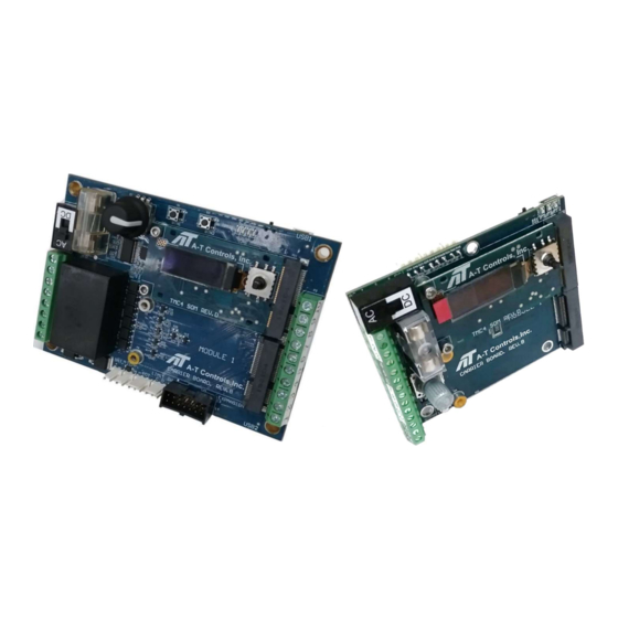
control options. It is available in two versions to accommodate a variety of actuator sizes. The TMC-4A002-001 controller
can control smaller actuators, and has a single option module slot, while the TMC-4A002-002 is used for controlling larger
actuators and has two option module slots.
When operated as a proportional controller, the TMC-4 compares an external command signal to a position feedback,
typically a potentiometer, that is coupled to the output shaft of the actuator. When the magnitude of the two signals differ
by a given magnitude, the TMC-4 controller will energize the motor to operate either clockwise or counterclockwise to
reduce the difference between the two signals.
When operated as two-position controller, the TMC-4 receives an open or close command, and drives the actuator
clockwise or counterclockwise until closure of a position limit switch is detected.
The TMC-4 must be installed in an appropriate enclosure to avoid electrical shocks. When operating,
high voltages will be present on the controller, requiring caution during the installation process. Power
should be deenergized before making wire connections to the TMC-4. A heater and thermostat
should be used when possible to prevent condensation.
www.atcontrols.com
TMC-4 Control Card (v2.02)
1
TMC-4 Control Card
for Electric Actuators
Installation & Operation Manual
03/18/21
IOM08139 REVISION 01
Advertisement

Related Manuals for A-T Controls TRIAO TMC-4

Summary of Contents for A-T Controls TRIAO TMC-4
- Page 1 TMC-4 Control Card for Electric Actuators Installation & Operation Manual Installation and Operation Manual TMC-4 Control Card (v2.02) 1. Overview The Triac TMC-4 control card is a motor controller intended to be used in electric actuators rated for running current loads up to 10 amps.
- Page 2 TMC-4 Control Card for Electric Actuators Installation & Operation Manual Layout 1.1.1. TMC-4A002-001 1.1.2. TMC-4A002-002 03/18/21 www.atcontrols.com IOM08139 REVISION 01...
- Page 3 TMC-4 Control Card for Electric Actuators Installation & Operation Manual Supply Type Switch Switch to select type of supply voltage. Set to “AC” for (P7) Feedback Potentiometer Header single phase AC supply voltage between 85V and 250V. 3 point connection header for feedback potentiometer Set to “DC”...
-
Page 4: Wiring And Operation
TMC-4 Control Card for Electric Actuators Installation & Maintenance Manual 2. Wiring and Operation The supply voltage and motor should be connected as brake output energizes. This configuration is for brakes shown in the wiring section. Set the Supply Type Switch that engage when unpowered and disengage when according to the supply voltage and select AC or DC powered. - Page 5 TMC-4 Control Card for Electric Actuators Installation & Maintenance Manual TMC-4A002-001 (P1) Function Terminals Supply L/+ Supply Power. Supply N/- Supply Power. Output that switches supply power when motor outputs are energized. Used for spring return electric actuator External brakes.
- Page 6 TMC-4 Control Card for Electric Actuators Installation & Maintenance Manual TMC-4A002-001 AC Proportional Control TMC-4A002-001 AC Two Position Control TMC-4A002-001 DC Proportional Control TMC-4A002-001 DC Two Position Control 03/18/21 www.atcontrols.com IOM08139 REVISION 01...
- Page 7 TMC-4 Control Card for Electric Actuators Installation & Maintenance Manual TMC-4A002-002 (P1) Motor / Supply Function Terminals Heater L/+ Fused output for heater. Heater N/- Neutral output for heater, connected to supply N. Supply L/+ Supply Power. Supply N/- Supply Power.
- Page 8 TMC-4 Control Card for Electric Actuators Installation & Maintenance Manual TMC-4A002-002 AC Proportional Control TMC-4A002-002 AC Two Position Control TMC-4A002-002 DC Proportional Control TMC-4A002-002 DC Two Position Control 03/18/21 www.atcontrols.com IOM08139 REVISION 01...
- Page 9 TMC-4 Control Card for Electric Actuators Installation & Maintenance Manual Input / Output Signal Configurations Command Type = mA Sinking Command Type = mA Sinking Externally Powered Loop Control 2-Wire Transmitter Control Command Type = mA Sourcing Command Type = mA Sourcing Externally Powered Loop Control 2-Wire Transmitter Control Command Type = 5V and 10V...
- Page 10 TMC-4 Control Card for Electric Actuators Installation & Maintenance Manual 3. Menu 03/18/21 www.atcontrols.com IOM08139 REVISION 01...
- Page 11 TMC-4 Control Card for Electric Actuators Installation & Maintenance Manual MAIN submenu The MAIN menu group contains various status screens displaying functional information such as positioning values, motor status and control parameters. Pressing [ LEFT ] from any screen will return to the Home screen. POS: Current travel position.
- Page 12 TMC-4 Control Card for Electric Actuators Installation & Maintenance Manual COMMAND CONFIG submenu The COMMAND CONFIG menu group contains various parameters that affect the control and response of the actuator. Sets type of command signal used. C O M M A N D T Y P E : 10V: 0-10V or 2-10V...
- Page 13 TMC-4 Control Card for Electric Actuators Installation & Maintenance Manual FEEDBACK CONFIG submenu Sets type of feedback signal. F E E D B A C K T Y P E : 10V: 0.0 to 10.8 VDC x x x x 0.0 to 21.5 mA Feedback Signal Type...
- Page 14 TMC-4 Control Card for Electric Actuators Installation & Maintenance Manual COMMS CONFIG submenu Sets type of communication protocol when using one of the communication module options. “Comms” command C O M M S type must be selected in the COMMAND CONFIG submenu. T Y P E : x x x x Modbus...
-
Page 15: Analog Control
TMC-4 Control Card for Electric Actuators Installation & Maintenance Manual 4. Setup and Calibration Feedback Potentiometer Adjustment A feedback potentiometer is used to detect the position of the actuator between the 0% to 100% limits for modulating and proportional control applications. The feedback potentiometer is coupled to the actuator output indicator shaft by a set of gears. -
Page 16: Two-Position Control
TMC-4 Control Card for Electric Actuators Installation & Maintenance Manual Two-Position Control For when operating as two position on/off actuator. 1) Set Supply Type Switch for AC or DC. 2) Set “Motor Type” in SYSTEM CONFIG for AC or DC to match Supply Type Switch setting. 3) Select On-Off input command. - Page 17 TMC-4 Control Card for Electric Actuators Installation & Maintenance Manual 5. Dimensions TMC-4A002-001 TMC-4A002-002 03/18/21 www.atcontrols.com IOM08139 REVISION 01...
-
Page 18: Specifications
TMC-4 Control Card for Electric Actuators Installation & Maintenance Manual 6. Specifications Power Switch AC: 85 – 250 VAC, 50/60Hz, 1 Phase Supply: Switch DC: 10-30 VDC Fuse: 10A, 250V, Time Delay, 5 x 20mm Command Signal In Voltage: -0.8 to 10.8 VDC Current: 0 to 23 mA 135Ω... - Page 19 Installation & Maintenance Manual A-T Controls product, when properly selected, is designed to perform its intended function safely during its useful life. However, the purchaser or user of A-T Controls products should be aware that A-T Controls products might be used in numerous applications under a wide variety of industrial service conditions.
Need help?
Do you have a question about the TRIAO TMC-4 and is the answer not in the manual?
Questions and answers