Table of Contents

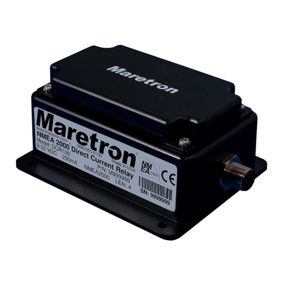
Summary of Contents for Maretron DCR100
- Page 1 ® ® DCR100 DC Relay Module User’s Manual Revision 1.1 Copyright ©2012 Maretron, LLP All Rights Reserved Maretron, LLP 9014 N. 23 Ave #10 Phoenix, AZ 85021-7850 http://www.maretron.com Maretron Manual Part #: M003001 Revision 1.1 Page i...
- Page 2 DCR100 User's Manual Revision History Revision Description Original document Added cautions about using red Loctite and acetone cleaners Clarified fuse requirements on installation wiring diagrams Page ii Revision 1.1...
-
Page 3: Table Of Contents
Installation Template ......................11 Maretron (2 Year) Limited Warranty ..................12 Table of Figures Figure 1 – Mounting the DCR100 ....................3 ® Figure 2 – NMEA 2000 Connector Face Views ............... 4 Figure 3 – DCR100 Connection Diagram .................. 5 ... - Page 4 DCR100 User's Manual This page intentionally left blank Page iv Revision 1.1...
-
Page 5: Introduction
Platinum software. The DCR100 easily handles resistive DC loads like lights, or inductive DC loads like pumps and motors. The DCR100 can also be used to switch AC circuits using external relays. An added benefit of the DCR100 is that it reports the current through each of the six channels. -
Page 6: Theory Of Operation
5. Configure the DCR100 (Section 2.5) 1.4 Theory of Operation The DCR100 provides the ability to turn on or off DC power to a load circuit using 6 independent, isolated solid state relays. The DCR100 is a solid state relay, not a circuit protection device. -
Page 7: Mounting The Dcr100
® ® The NMEA 2000 connector can be found on the side of the enclosure. The NMEA 2000 connector is a round five pin male connector (see Figure 2). You connect the DCR100 to an ® ® NMEA 2000 network using a Maretron NMEA 2000... -
Page 8: Switched Power Connections
Connector Face Views 2.4.2 Switched Power Connections The DCR100 switched power connections are made by connecting to the 12-pin terminal strip on the top of the unit. First, remove the four screws at the corners of the unit detaching the splash guard from the unit. -
Page 9: Protection
This fuse or circuit breaker must be sized to be no larger than 10A. For example, if you are using all six channels of the DCR100, there must be 6 circuit breakers and a separate power lead from each circuit breaker to the Px terminal for each channel. -
Page 10: Configuring The Dcr100
“Troubleshooting”. 2.5 Configuring the DCR100 The DCR100 will transmit data over the NMEA 2000 network as it is shipped from the factory; however, it may require configuration, depending on the type of switch monitored. There are several configurable items within the DCR100, which are detailed in the remainder of this section. -
Page 11: Instance
2.5.4 Switch Control This menu allows you to see the current state of each switch on the DCR100 (“On”, “Off”, or “Error”). It also allows you to set each switch to the ON or OFF state. Setting the switch to the Off State will clear an Error condition. - Page 12 • Ensure that the DCR100 has the appropriate NMEA 2000 ® PGNs enabled as described in Section 2.5.1.1. A breaker/switch always The DCR100 may have shut down the affected channel due to an reads “Error” overtemperature or overcurrent condition detected on the DCR100 relay itself.
-
Page 13: Technical Specifications
® ® 5 Technical Specifications As Maretron is constantly improving its products, all specifications are subject to change without notice. Maretron products are designed to be accurate and reliable; however, they should be used only as aids to navigation and not as a replacement for traditional navigation aids and techniques. -
Page 14: Technical Support
DCR100 User's Manual 6 Technical Support If you require technical support for Maretron products, you can reach us in any of the following ways: Telephone: 1-866-550-9100 Fax: 1-602-861-1777 E-mail: support@maretron.com World Wide Web: http://www.maretron.com Mail: Maretron, LLC Attn: Technical Support 9014 N. -
Page 15: Installation Template
® ® 7 Installation Template Please check the dimensions before using the following diagram as a template for drilling the mounting holes because the printing process may have distorted the dimensions. Figure 4 – Mounting Surface Template Revision 1.1 Page 11... -
Page 16: Maretron (2 Year) Limited Warranty
8 Maretron (2 Year) Limited Warranty Maretron warrants the DCR100 to be free from defects in materials and workmanship for two (2) years from the date of original purchase. If within the applicable period any such products shall be proved to Maretron’s satisfaction to fail to meet the above limited warranty, such products shall be repaired or replaced at Maretron’s... -
Page 17: Appendix A - Nmea 2000 Interfacing
Periodic Data Transmitted PGNs PGN 127501 – Binary Switch Bank Status The DCR100 uses this PGN to transmit the state of each of the connected switch inputs Field 1: Indicator Bank Instance – This field identifies the particular switch bank to which this PGN applies. - Page 18 6: Relay Current – This field indicates the current flowing through the relay channel in units of 0.1A. 7: Reserved – This field is reserved by Maretron; therefore, this field always contains a value of 0xFFFF (the DCR100 sets all reserved bits to a logic 1).
Need help?
Do you have a question about the DCR100 and is the answer not in the manual?
Questions and answers