
Summary of Contents for Jabuga REM Mobile Children's Loft Bed
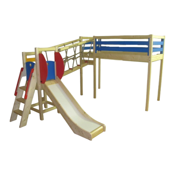
- Page 1 All manuals and user guides at all-guides.com Assembly Manual REM mobile children’s loft bed combination with slide and rope bridge...
- Page 2 If you do not feel comfortable enough about your handicraft skills, we recommend that you hire a specialist to perform the job. We wish you the best of luck in assembling this loft, which will give pleasure to your child for many years. Kindest regards: Jabuga...
- Page 3 All manuals and user guides at all-guides.com Alignment This assembly manual has been prepared based on a left alignment. In case of right alignment, you should not interpret literally the leg markings of the bed, but you should rather identify the applicable matching elements based on the floor plan.
- Page 4 All manuals and user guides at all-guides.com Floor plan...
-
Page 5: Checklist Of Components
All manuals and user guides at all-guides.com Checklist of components Please check if you have found all the necessary component parts in the package. - Page 6 All manuals and user guides at all-guides.com Components Barrel nut and bolt, m8*100 60 pcs...
- Page 7 All manuals and user guides at all-guides.com Alkatrészek Barrel nut and bolt, m8*80 2 pcs...
- Page 8 All manuals and user guides at all-guides.com Components Threaded rod, underlay, nut, cap 1 of each...
- Page 9 All manuals and user guides at all-guides.com Components Screws, 5*70 7 pcs...
- Page 10 All manuals and user guides at all-guides.com Components Screws, 4*70 40 pcs...
- Page 11 All manuals and user guides at all-guides.com Components Screws 4*50 6 pcs...
- Page 12 All manuals and user guides at all-guides.com Components Screws, 3*40 14 pcs...
- Page 13 All manuals and user guides at all-guides.com Components Hand-wheel 2 pcs...
- Page 14 All manuals and user guides at all-guides.com Necessary tools You will need a No. 4 imbus key, a straight screwdriver, an electric screwdriver with PZ 2 and PZ 1 hex bits and a No. 13 fork spanner. A tape measure and an H4 imbus bit may also come in handy.
- Page 15 All manuals and user guides at all-guides.com Necessary tools In case you do not possess an electric screwdriver, a drill with screwdriving function or in last case, a simple hand screwdriver may do the job as well.
- Page 16 All manuals and user guides at all-guides.com Necessary tools At the end of the work, you may feel a great need for a relaxation drink.
- Page 17 All manuals and user guides at all-guides.com Important information! As a result of individual, hand made threading, pine chips and shavings may remain in the thread hole which could be driven into the screw hole by the inserted screw. These holes are checked by us in all cases, but for security reasons, you should also follow the following steps.
- Page 18 All manuals and user guides at all-guides.com Important information Insert the screw horizontally into the empty thread hole. Check to see if there are any pine chips in the hole.
- Page 19 All manuals and user guides at all-guides.com Important information In case you found any pine chips in front of the screw, place the screw into the vertical thread, and use it as a rasper, to get rid of the shavings. Blow out the remaining shavings.
- Page 20 All manuals and user guides at all-guides.com Important information Once you have made sure that the threaded hole is now clear, place the bolt into the vertical hole. Be careful to have the slot on the top and hole of the barrel nut pointing toward the horizontal thread.
- Page 21 All manuals and user guides at all-guides.com Important information If necessary, push the barrel nut down the hole using an imbus key or a screw driver stem.
- Page 22 All manuals and user guides at all-guides.com Important information Lead the stem of the imbus key (or the stem of another thin tool), in order to adjust the barrel nut into its proper height and direction.
- Page 23 All manuals and user guides at all-guides.com Important information While tightening the screws, you may keep the barrel nut in place with the help of a straight screwdriver. Never force a jamming screw! If this happens, disassemble and repeat the process.
- Page 24 All manuals and user guides at all-guides.com Additional important information Each leg is numbered accoring to the floor plan and includes a hidden adjustable sole. Before setting up a leg, please unscrew the adjustable sole in order that it points beyond the wooden material by 1-2 mm.
- Page 25 All manuals and user guides at all-guides.com Important information Barrel nut threaded holes always face toward the inner side the combinational elements.
-
Page 26: Assmebly Step By Step
All manuals and user guides at all-guides.com Assmebly step by step • Unpack every element. • Clear the space to be built in. • Follow the steps. • Watch the markings and numbering on the elements. - Page 27 All manuals and user guides at all-guides.com First step Place you drink into the fridge, hogy mire végez megfelelő hőmérsékletű legyen.
- Page 28 All manuals and user guides at all-guides.com Fent UP Lent Down...
- Page 29 All manuals and user guides at all-guides.com Fent No. 1 Short connector Lent DOWN Outer side of Tower L1, L2 No. 1, Short connector (6,4*4*44) No.1: Marking on element: arrow points toward upper edge.
- Page 30 All manuals and user guides at all-guides.com No. 2 Tower side from direction of rope bridge L3, L4 No. 2, Short connector No. 2: Marking on element: Arrow points toward upper edge.
- Page 31 All manuals and user guides at all-guides.com No. 3 Tower connectors Short connectors Element No. 3...
- Page 32 All manuals and user guides at all-guides.com No. 3 No. 4 Tower connectors Short connectors No. 4...
- Page 33 All manuals and user guides at all-guides.com Assembly of tower...
- Page 34 All manuals and user guides at all-guides.com No. 6 No. 5 Bed side from direction of rope bridge L5, L6 No. 5 , No. 6 No. 6: Marking on elemet: arrow points toward upper edge...
- Page 35 All manuals and user guides at all-guides.com No. 6 No. 6 element into appropriate holes...
- Page 36 All manuals and user guides at all-guides.com Components Threaded rod, underlay, nut, cap 1 of each...
- Page 37 All manuals and user guides at all-guides.com No. 5 No. 5 + component Screw threaded rod until collision.
- Page 38 All manuals and user guides at all-guides.com No.7 No. 8 Short side of bed No. 7, No. 8 No. 7: Marking on element: Arrow points toward upper edge. No. 8: Marking on element: marks edge from L5.
- Page 39 All manuals and user guides at all-guides.com No.9 Short side of bed L8, L9 No.9, Connector No. 9: Marking on element: Arrow points toward upper edge.
- Page 40 All manuals and user guides at all-guides.com Components Barrel nut and bolt, m8*80 2 pcs...
- Page 41 All manuals and user guides at all-guides.com Screw point of rope bridge from direction of tower Marking on element: Marks the side from tower (lower side). Please ask for assistance.
- Page 42 All manuals and user guides at all-guides.com Screw point of rope bridge from direction of bed Drive in the screw, but not too tightly – just enough so the elements will not fall apart. Leave enough gap so you can insert the upper handholds.
- Page 43 All manuals and user guides at all-guides.com Rope bridge handholds Insert one of the handholds, but do not fully tighten screws. Insert the other handhold, then tighten all of the screws.
- Page 44 All manuals and user guides at all-guides.com Long bedside Please ask for assistance.
- Page 45 All manuals and user guides at all-guides.com Long bedside connector Please ask for assistance.
- Page 46 All manuals and user guides at all-guides.com Short bedside Do not fully tighten screws.
- Page 47 All manuals and user guides at all-guides.com Component Take nut and underlay off the threaded rod.
- Page 48 All manuals and user guides at all-guides.com Long bedside Insert the element into position diagonally.
- Page 49 All manuals and user guides at all-guides.com Long bedside Placethe element into position.
- Page 50 All manuals and user guides at all-guides.com Long bedside Do not tighten screws.
- Page 51 All manuals and user guides at all-guides.com Long bedside connector Do not tighten screws.
- Page 52 All manuals and user guides at all-guides.com Component...
- Page 53 All manuals and user guides at all-guides.com Component...
- Page 54 All manuals and user guides at all-guides.com Components Screw, 5*70 3 pcs...
- Page 55 All manuals and user guides at all-guides.com Component...
- Page 56 All manuals and user guides at all-guides.com Middle bed slat support Please ask for assistance. Do not tighten screws.
- Page 57 All manuals and user guides at all-guides.com Alkatrészek Screws, 4*70 x pcs...
- Page 58 All manuals and user guides at all-guides.com Guardrail insert Put guardrail in place. If necessary, loosen screwpoints and legs, so the element may be inserted without forcing. Once the element is in place, fix it by screwing on one side, then tighten the screwpoint. Then screw and fix the other side as well.
- Page 59 All manuals and user guides at all-guides.com Guardrail insert in the tower Screw points and screws should be tightened only after strip flooring has been put in its place.
- Page 60 All manuals and user guides at all-guides.com Components Screws, 3*40 10 pcs...
- Page 61 All manuals and user guides at all-guides.com Strip flooring Fix the elements by screwing diagonally into the groove, beginning from about 2 cm-s from the edge. Pre-drilling is not necessary, you may drive the screw directly into the material. If necessary, loosen the screw point in order to insert strip floor elements.
- Page 62 All manuals and user guides at all-guides.com Strip flooring Fix the last element by screwing vertically at about 2 cm- s from the edge.
- Page 63 All manuals and user guides at all-guides.com Strip flooring After fixing the strip flooring,tighten each screw and screwpoint.
- Page 64 All manuals and user guides at all-guides.com Alkatrészek Screws, 5*70 4 pcs...
- Page 65 All manuals and user guides at all-guides.com Stairs The inner edge of the leg and the side of the stairs should be in line.
- Page 66 All manuals and user guides at all-guides.com Components Hand wheels 2 pcs...
- Page 67 All manuals and user guides at all-guides.com Slide body and ”ears” Place the slide in position, and fix the right ear onto it using the handwheel.
- Page 68 All manuals and user guides at all-guides.com Slide body and ”ears” Adjust the slide into its place. Do not leave any gaps.
- Page 69 All manuals and user guides at all-guides.com Components Screws 4*50 6 pcs...
- Page 70 All manuals and user guides at all-guides.com Slide body and ”ears” Fix the element by screwing.
- Page 71 All manuals and user guides at all-guides.com Slide body and ”ears” Fix the other element the same way.
- Page 72 All manuals and user guides at all-guides.com Optional: Blocking panel...
- Page 73 All manuals and user guides at all-guides.com Components Screws, 4*70 8 pcs...
- Page 74 All manuals and user guides at all-guides.com Handholds Fix both handholds...
- Page 75 All manuals and user guides at all-guides.com Components Screws, 3*40 4 pcs...
- Page 76 All manuals and user guides at all-guides.com Optional: Blocking panel rail...
- Page 77 All manuals and user guides at all-guides.com Optional: Blocking panel...
- Page 78 All manuals and user guides at all-guides.com The combination is finished! If you had followed every step correctly, then your product is now finished. Insert bed slats and the matresse into the bed place. After that, you have nothing else to do, just lay back, open your (by now) cold drink, and watch your kids as they occupy their new bedroom.
- Page 79 All manuals and user guides at all-guides.com Optional: fixing to the wall Basically, this combination does not require fastening to the wall. But, if you would like additional steadiness to your product, then the attached guide will follow you through the necessary steps. Holes are not prepared for this step.
- Page 80 All manuals and user guides at all-guides.com Optional: Straight ladder leading up to the bed In the future, once your child feels she/he is „grown up” and no longer wishes to use the tower attachment, you have the opportunity to diassemble it, and replace it with a straight ladder, using the short connectors of the tower between legs L5 and L6.
- Page 81 All manuals and user guides at all-guides.com No. 6 Optional: Straight ladder Disassemble the tower and loosen the nodes of leg L5, the bed slat support in the middle, and leg L7 láb, in order to remove element No. 6. You will need to temporarily remove the short side guard rail insert.
- Page 82 All manuals and user guides at all-guides.com Necessary tools 10 mm wood drill, clamp Wooden pads (from components package)
- Page 83 All manuals and user guides at all-guides.com Belső oldal Inside No. 6 No. 5 Optional: Straight ladder For aesthetic reasons, the holes are simply prepared but are not drilled through. Using a 10 mm drill wood drill stem, drill the lower hole both sides of legs L5 and L6, for the passing screw.
- Page 84 All manuals and user guides at all-guides.com Optional: Straight ladder Drill though the lower hole of each screw point.
- Page 85 All manuals and user guides at all-guides.com Optional: Straight ladder If possible, try to drill the material in a way that it dollies the provided wood strip. This way disruption of the back side may be prevented. Make sure to use a sharp drill! Do not overstrain the clamp, otherwise it will leave marks on the material.
- Page 86 All manuals and user guides at all-guides.com Optional: Straight ladder Screw the short connectors in the usual way. These will function as the ladder steps. Because of the nature of the hole, you may find that the elements tilt a bit during use. If this happens, adjust the element and tighten the screw.
- Page 87 All manuals and user guides at all-guides.com Finally! Now it is really…. The end …now you can relax.
- Page 88 All manuals and user guides at all-guides.com Thank you for your purchase! We wish many merry moments for your child.
Need help?
Do you have a question about the REM Mobile Children's Loft Bed and is the answer not in the manual?
Questions and answers