Advertisement
Table of Contents
3170 Wasson Road • Cincinnati, OH 45209
Phone 513.533.5600 • Fax 513.871.0105 (f)
info@richardsind.com • www.jordanvalve.com
Warning: Jordan Valve Control Valves must only be used, installed and repaired in accordance with these Installa-
tion & Maintenance Instructions. Observe all applicable public and company codes and regulations. In the event
of leakage or other malfunction, call a qualified service person; continued operation may cause system failure or
a general hazard. Before servicing any valve, disconnect, shut off, or bypass all pressurized fluid. Before disassem-
bling a valve, be sure to release all spring tension.
I
nstallatIon
Warning:
Service conditions must not exceed the limits shown
on the valve nameplate, or those outlined in this
manual. Consequences could include bursting of
pressure-retaining parts and uncontrolled process
fluid, resulting in personal injury or property damage.
Control valves should also be protected from external
damages.
Prior to installing the Mark 128PQC Series Control
Valve, perform a complete inspection for damage,
and remove any foreign debris. Position the valve for
desired flow direction. If angle flow is required, switch
the pipe plug to left-hand connection. (Figure 2)
3
1/4 INCH NPT
PRESSURE
CONNECTION
LEAKOFF
VENTS
23
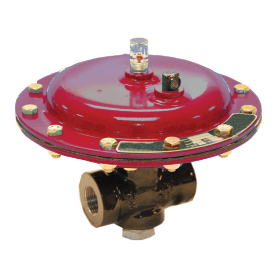
Mark 128PQC Control Valve with Fail-Close Action
Figure 1: Mark 128PQC Control Valve Typical Constructions
I & M Mark 128PQC Series
Installation & Maintenance Instructions for the
Mark128PQC Series Control Valves
The versatility of this valve allows for installation in any
orientation, with the standard method being with the
actuator above the body. Standard orientation is best
when an angle body or angle configuration has been
specified.
When installing the valve into the line, accepted piping
practices must be used. A three-valve bypass should
be used if continuous operation is required during
inspection or maintenance.
For a fail-close control valve, connect the input signal
line into the 1/4-inch NPT actuator connection (Figure
1) in the lower diaphragm case assembly. The input
signal pressure line should be installed in the upper
diaphragm case assembly of a fail-open control valve.
35
21
28
Detail of Mark 128PQC
Exterior
Advertisement
Table of Contents

Related Manuals for Jordan Valve Marc 128PQC Series

Summary of Contents for Jordan Valve Marc 128PQC Series
- Page 1 Mark128PQC Series Control Valves info@richardsind.com • www.jordanvalve.com Warning: Jordan Valve Control Valves must only be used, installed and repaired in accordance with these Installa- tion & Maintenance Instructions. Observe all applicable public and company codes and regulations. In the event of leakage or other malfunction, call a qualified service person;...
-
Page 2: Maintenance
128PQC S erieS ontrol alVe aIntenance Replacing Packing and Trim Follow these procedures when replacing the entire pack- Warning: ing and trim assembly or individually replacing packing Prior to performing any maintenance, isolate the valve from and trim parts. Unless otherwise indicated, key num- the process pressure. - Page 3 128PQC S erieS ontrol alVe Fix the valve plug onto the stem, rotating the Replacing Packing and Trim continued, plug until the shoulder makes snug contact Accessible areas should be cleaned at this with the stem. No further tightening is neces- stage, and all necessary maintenance perf- sary.
- Page 4 128PQC S erieS ontrol alVe Changing Main Spring Range Reversing Action or Replacing Actuator Parts Unless otherwise indicated, refer to Table 2 for parts Unless otherwise indicated, refer to Table 2 for parts listings for replacement packing and trim assembly, listings for replacement packing and trim assembly, Figure 2 for packing and trim assembly key numbers Figure 2 for packing and trim assembly key numbers...
-
Page 5: Parts Ordering
128PQC S erieS ontrol alVe Reversing Action or Replacing Actuator Parts arts rderIng cont’d Mark 128-PQC valves have individual serial numbers, Perform the following assembly sequenc- found on the valve nameplate. Please refer to that es as necessary to achieve the required number when ordering parts or contacting your Jordan control valve action: Valve Sales Representative. - Page 6 128PQC S erieS ontrol alVe Table 2: Replacement Packing and Trim Assembly Part Numbers TFE V-Ring Packing, Nitronic 50 SST TFE Ring Packing and Heat-Treated Port Diameter Valve Plug and Cage, and Inconel 44OC SST Valve Plug and Cage X750 Packing Spring Mark 128PQC 17-7PH SST Mark 128 PQC Packing Spring...
- Page 7 128PQC S erieS ontrol alVe Mark 128PQC Control Valve: Fail-Closed with Cage-Style Metal Seat and Single TFE-V-Ring Packing Mark 128PQC Cageless Soft-Seat Detail Fail-Open Actuator Detail Figure 4: Typical Mark 128PQC Series Control Valve Assembly...
-
Page 8: Parts List
128PQC S erieS ontrol alVe arts Description Part Number Upper Diaphragm Casing, Steel 24A8816X012 Spring Plate, Zinc Plated Steel 14A8819X012 Vent Assembly 1C8937000A2 Washer, Steel 1A742328992 Indicator Bushing, 316 SST 13A2323X012 Indicator Cover, Plastic 15A1580X012 Travel Indicator Disc Nut, Plastic 1F730506992 Machine Screw, SST 14A8818X012... -
Page 9: P Arts L Ist C Ont
Paper Label Protective Sleeve-Web Cage Puller 15A2525X012 Keys 5, 7, 8, 9, 10, 11 Complete Assembly 35A1588X0A2 Jordan Valve, a division of Richards Industries 3170 Wasson Road • Cincinnati, OH 45209 513.533.5600 • 800.543.7311 • 513.871.0105 (f) info@richardsind.com • www.jordanvalve.com...
Need help?
Do you have a question about the Marc 128PQC Series and is the answer not in the manual?
Questions and answers