Table of Contents
Advertisement
Quick Links
SM7860
SM7860-51
SM7860-52
SM7860-53
SM7860-54
SM7860-55
SM7860-56
SM7860-57
SM7860-58
POWER SOURCE UNIT
Be sure to read this manual
before using the device
When using the device for the first time
Part Names and Functions
Screen Configuration
Installation and Connection Procedures p. 15
July 2018 Revised edition 1
SM7860J961-01 18-07H
SM7860-61
SM7860-62
SM7860-63
SM7860-64
SM7860-65
SM7860-66
SM7860-67
SM7860-68
Safety Information p. 4
Troubleshooting
p. 10
Troubleshooting
p. 13
Error Display
Instruction Manual
p. 53
p. 55
EN
Advertisement
Table of Contents

Related Manuals for Hioki SM7860 Series

Summary of Contents for Hioki SM7860 Series
- Page 1 SM7860 SM7860-51 SM7860-61 SM7860-52 SM7860-62 SM7860-53 SM7860-63 Instruction Manual SM7860-54 SM7860-64 SM7860-55 SM7860-65 SM7860-56 SM7860-66 SM7860-57 SM7860-67 SM7860-58 SM7860-68 POWER SOURCE UNIT Be sure to read this manual Safety Information p. 4 before using the device When using the device for the first time Troubleshooting Part Names and Functions ...
-
Page 3: Table Of Contents
Contents Introduction ............1 External Control Notation ..............2 Verifying Package Contents ......3 EXT I/O Connector and Signals ..37 Safety Information ..........4 Connector Type and Signal Pinouts ...38 Operating Precautions ........4 ........39 Signal Functions Timing Chart ..........40 Overview Internal Circuitry ........44 Product Overview and Features ...9 Specifications Part Names and Functions... - Page 4 Contents...
-
Page 5: Introduction
Introduction Introduction Thank you for purchasing the Hioki Model SM7860 series Power Source Unit. To obtain maximum performance from the device over the long term, be sure to read this manual carefully and keep it handy for future reference. Target audience This manual has been written for use by individuals who use the product in question or who teach others to do so. -
Page 6: Notation
Notation Notation Concerning Safety In this document, the risk seriousness and the hazard levels are classified as follows. DANGER Imminent risk of operator death or serious injury WARNING Potential for operator death or serious injury CAUTION Potential for minor operator injury or device damage or malfunction Indicates information related to the operation of the device or maintenance tasks IMPORTANT with which the operators must be fully familiar. -
Page 7: Verifying Package Contents
Confirm that you have received the following items: Model SM7860 series Power Source Unit Power cord Instruction Manual (This document) Options The following options are available for the device. Contact your authorized Hioki distributor or reseller when ordering. Model 9637 RS-232C Cable (9pin-9pin/1.8 m) Cross... -
Page 8: Safety Information
• Verify that the device operates normally to ensure that no damage occurred during storage or shipping. If you find any damage, contact your authorized Hioki distributor or reseller. WARNING To prevent an electric shock, confirm that the white or red portion (insulation layer) inside the cable is not exposed. - Page 9 Operating Precautions Installing the device WARNING • Ventilation holes for heat radiation are provided on the side and rear panels of the device. Leave sufficient space around the ventilation holes and install the device with the holes unobstructed. Installation of the device with the ventilation holes obstructed may cause a malfunction or a fire.
- Page 10 Operating Precautions Installing Prolonged operation in hot temperatures will shorten the device’s service life. Keep the ambient temperature as low as possible. • Avoid obstructing the ventilation holes. • To prevent overheating, be sure to leave the specified clearances around the device. •...
- Page 11 Operating Precautions Handling the Cords WARNING If the insulation on a cord melts, the metal conductor may be exposed. Do not use any cord whose metal conductor is exposed. Doing so could result in an electric shock, burn, or other hazards. CAUTION To avoid damaging the power cord, grasp the plug, not the cord, when unplugging it from the outlet or device.
- Page 12 Operating Precautions...
-
Page 13: Overview
Overview 1.1 Product Overview and Features The SM7860 series Power Source Unit is a power source designed for use with the SM7420 Super Ω Megohm Meter and SM7810‑20 Super M HiTester. When used in conjunction with the SM7420 or SM7810‑20, the SM7860 serves as an ideal power source for automatic testing and measurement of capacitors. -
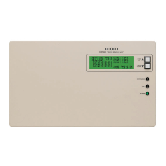
Page 14: Part Names And Functions
Part Names and Functions 1.2 Part Names and Functions Front Display (LCD) The screen uses a 2‑page layout to display setting values and setting status information. Refer to “1.3 Screen Configuration” (p. 13) Scroll keys • Use to scroll the display (LCD). [PAGE UP▲], [PAGE DOWN▼]... - Page 15 Part Names and Functions Rear Voltage output terminal Voltage is output. Connect the optional Model L2221 Connector. Refer to “2.3 Connecting the Device to the Measuring Instrument” (p. 17) Ventilation holes Keep clear of obstructions. Refer to “Installing” (p. 6) Power switch (POWER) Turns the device on and off.
- Page 16 Part Names and Functions Side Handle (total of 4, located on the It should be moved by at least two people, who should grip left and right sides of the device) it using the handles on the left and right sides. Ventilation holes Keep clear of obstructions.
-
Page 17: Screen Configuration
Screen Configuration 1.3 Screen Configuration The display (LCD) consists of two display pages (Screen P1, Screen P2). • Screen P1 is displayed when the device is turned on. • The display pages can be scrolled using the scroll keys ([PAGE UP▲], [PAGE DOWN▼]) to the right of... - Page 18 Screen Configuration CLM1 Output current limit value : OUT1 output current limit value setting display CLM2 : OUT2 output current limit value setting display CLM3 : OUT3 output current limit value setting display CLM4 : OUT4 output current limit value setting display The digit following corresponds to OUT1 to 4.
-
Page 19: Preparation And Supply Power
Preparation and Supply Power 2.1 Installation and Connection Procedures Be sure to read the “Operating Precautions” (p. 4) before installing and connecting the device. Front Rear Install the device. (p. 5) Connect the power cord. (p. 16) Connect the device to the measuring instrument. (p. 17) Connect the external interface. -
Page 20: Connecting The Power Cord
Connecting the Power Cord 2.2 Connecting the Power Cord WARNING • Before turning the device on, make sure the supply voltage matches that indicated on its power connector. Connection to an improper supply voltage may damage the device and present an electrical hazard. •... -
Page 21: Connecting The Device To The Measuring Instrument
Connecting the Device to the Measuring Instrument 2.3 Connecting the Device to the Measuring Instrument WARNING To prevent an electric shock or damage to the equipment, always observe the following precautions when connecting to voltage output terminal: • Always turn off the device and any devices to be connected before connecting the voltage output connectors. -
Page 22: Inspection Before Operation
Inspection Before Operation 2.4 Inspection Before Operation Verify that the device operates normally to ensure that no damage occurred during storage or shipping. If you find any damage, contact your authorized Hioki distributor or reseller. Inspection of peripheral devices Exposed •... -
Page 23: Turn On/Off The Power
Turn ON/OFF the power 2.5 Turn ON/OFF the power WARNING Before turning the device on, make sure the supply voltage matches that indicated on its power connector. Connection to an improper supply voltage may damage the device and present an electrical hazard. When turning the device on and off, do not touch the voltage output terminals. -
Page 24: Operating Conditions Setting
Operating Conditions Setting 2.6 Operating Conditions Setting This section describes how to set the operating conditions according to the manner in which the device is to be used. Settings are configured via either of the device’s external interfaces: Refer to “3 Changing the Interface” (p. 23) The device cannot be configured directly in a standalone manner. -
Page 25: Output Setting For The Device Interlocked
Output Setting for the Device Interlocked 2.7 Output Setting for the Device Interlocked This section describes how to choose between an impedance state and a discharging state for the output with the device interlocked. This setting remains the same even after the device is initialized. ILOCK DCHG: OFF High-impedance state (Default) ILOCK DCHG: ON... - Page 26 Output Setting for the Device Interlocked...
-
Page 27: Changing The Interface
Changing the Interface The mark shown below indicates that the following instructions are specific to the RS-232C or the GP-IB interface. Instructions without these symbols are for both the RS-232C and the GP-IB interface. GP-IB GP-IB interface only RS-232C RS-232C interface only Before communicating When connecting a GP-IB or RS-232 cable, be sure to secure the connector in place with screws or other appropriate hardware. -
Page 28: Interface Specifications
Interface Specifications 3.2 Interface Specifications Precautions RS-232C and GP-IB communications cannot be used simultaneously. GP-IB (1) GP-IB Specifications • Electrical machinery specifications: IEEE std. 488.1-1987 compliant • Address setting: Can be set to talker/listener addresses 1 to 30. Interface Functions ... - Page 29 Interface Specifications (2) RS-232C Specifications RS-232C Transfer method Communication method: Full duplex Synchronization method: Asynchronous Transmission rate 38400 bps fixed Data bit length 8 bits Stop bit 1 bit Parity bit None Delimiter Transmit: CR+LF Receive: CR, CR+LF Flow control No X flow control, no hardware flow control Protocol Electrical...
-
Page 30: Connecting The Interface
Connecting the Interface 3.3 Connecting the Interface WARNING • To avoid equipment failure, do not disconnect the communications cable while communications are in progress. • Use a common ground for both the device and the PC. Using different ground circuits will result in a potential difference between the device’s ground and the PC’s ground. -
Page 31: Configuring The Communications Protocol
Configuring the Communications Protocol When connecting the device to a PC Use a crossover cable with female 9-pin D-sub connectors. Crossover Wiring Female 9-pin D-sub Female 9-pin D-sub Recommended cable: Model 9637 RS-232C Cable (9 pin- PC/AT Enhanced SM7860 side 9 pin/1.8 m) Graphics Adapter Pin No. -
Page 32: Configuring Rs-232C Interface
Communication Method Configuring RS-232C Interface Communications RS-232C Set the communications protocol on the controller (PC, etc.) to the same communications settings. For more information about how to configure these settings, refer to the controller’s instruction manual or other documentation. Communication conditions Baud rate 38400 bps Parity... - Page 33 Communication Method Program Messages Command Messages and Query Messages Command Messages Commands that control the device, for example to configure settings or reset the device. Query Messages Requests for responses relating to results of operation or measurement, or the state of device settings. Query commands end with a question (?) mark.
-
Page 34: Status Byte Register
Communication Method Status Byte Register RS-232C : RS-232C reads the status bytes to find out the status of the device. GP-IB : The device adopts the IEEE488.1-1987 defined status model for parts related to the serial polling performed by the service request function. A trigger for generating a service request is called an event. -
Page 35: Event Register
Communication Method Status Byte Register (STB) A status byte register is an 8-bit register output from the unit to the controller during serial polling. If even one of the status byte register bits enabled by the service request enable register changes from “0” to “1”... - Page 36 Communication Method Bit 7 Power-On Flag Set to “1” when the power is turned on, or upon recovery from an outage. Bit 6 User Request Unused Bit 5 Command error (The command to the message terminator is ignored.) This bit is set to “1” when a received command contains a syntactic or semantic error: •...
-
Page 37: Error Register
Communication Method Error Register The Error Register, which consists of 8 bits, manages error information. The contents of this register are aggregated in the CME, EXE, DDE, and QYE bits of the Standard Event Status Register (no mask processing is performed). Error register-related message are listed below. -
Page 38: Message List
Message List 3.6 Message List RS-232C RS-232C-only commands are indicated by . When using the RS-232C interface to send commands, include a uniform wait time of 100 ms (excluding the following exceptions). Command Description Format Communication condition RS-232C Remote switching request [Format] RMT Delimiter Talker delimiter specification... - Page 39 ∗IDN? Returns the device’s hardware ID as the response. [Response] d1: String d1 (HIOKI, SM7860-5x, 0, 01.00) or d1 (HIOKI, SM7860-6x, 0, 01.00) ∗ SAV Save environmental data (output voltage setting, current limit value, and [Format] ∗SAV d1 alarm setting) d1: NR1 d1 (Environmental data no.: 0 to 3)
-
Page 40: Listener Specification Precautions
Listener Specification Precautions Command Description Format ∗ ESE? Standard event status enable register query [Format] ∗ESE? The contents of responses are the same as the settings. [Response] d1: NR1 format ∗ ESR? Standard event status register query [Format] ∗ESR? d1 (0 to 255) [Response] d1: NR1 format... -
Page 41: External Control
External Control This chapter describes how to use the EXT I/O connector on the rear of the device to control the device. 4.1 EXT I/O Connector and Signals WARNING To prevent an electric shock or damage to the equipment, always observe the following precautions when connecting the cables to EXT I/O connector: •... -
Page 42: Connector Type And Signal Pinouts
EXT I/O Connector and Signals Connector Type and Signal Pinouts Connector: 57RE-40500-730B (50 pin: DDK) 26 27 28 29 30 31 32 33 34 35 36 37 38 39 40 41 42 43 44 45 46 47 48 49 50 1 2 3 4 5 6 7 8 9 10 11 12 13 14 15 16 17 18 19 20 21 22 23 24 25 EXT I/O connector Pin No. -
Page 43: Signal Functions
EXT I/O Connector and Signals Signal Functions Input Signals EXT_DCV2 (+24V) External power source input OUTPUT Output on/off setting OUT1 (1)_ON to OUT1 (8)_ON Specific-channel on/off setting OUT2 (1)_ON to OUT2 (8)_ON Specific-channel on/off setting OUT3 (1)_ON to OUT3 (8)_ON Specific-channel on/off setting OUT4 (1)_ON to OUT4 (8)_ON Specific-channel on/off setting... -
Page 44: Timing Chart
Timing Chart 4.2 Timing Chart Each signal level indicates a corresponding voltage level. EXT I/O connector OUT1 (1)_ON to (8)_ON OUT2 (1)_ON to (8)_ON OUT3 (1)_ON to (8)_ON OUT4 (1)_ON to (8)_ON OUTPUT BUSY ALARM Previous ALARM result New ALARM result Voltage output terminal OUT1 (CH1) to (CH8) OUT2 (CH1) to (CH8) - Page 45 Timing Chart Timing Chart Interval Descriptions Interval Description Duration Channel setup time 100 μs or more Channel hold time 200 μs or more Output on → Busy delay time 200 μs or less Output on → Voltage output delay time 600 μs or less Alarm delay time 3.5 ms or less...
- Page 46 Timing Chart When the output setting for the device interlocked is set to the discharging state EXT I/O connector INTERLOCK Voltage output terminal OUT1 (CH1) to (CH8) OUT2 (CH1) to (CH8) OUT3 (CH1) to (CH8) OUT4 (CH1) to (CH8) Internal voltage Setting voltage Setting voltage Circuit A, B *...
- Page 47 Timing Chart When the output setting for the device interlocked is set to the high-impedance state EXT I/O connector INTERLOCK OUT1 (CH1) to (CH8) OUT2 (CH1) to (CH8) OUT3 (CH1) to (CH8) OUT4 (CH1) to (CH8) High-impedance...
-
Page 48: Internal Circuitry
Internal Circuitry 4.3 Internal Circuitry Input Circuit 24 V DC EXT_DC2 Input signals External device side SM7860 side Output Circuit 5 V DC to 24 V DC Output signals External device side SM7860 side Input method Photocoupler-isolated input Input Signals Input voltage Input voltage LOW: 0 V to 0.5 V, HIGH: 24 V±10% Output method... -
Page 49: Specifications
Specifications 5.1 General Specifications Operating Indoors, Pollution degree 2, up to 2000 m (6562 ft.) environment Operating 0°C to 60°C (32°F to 140°F), 80% RH or less (no condensation) temperature and humidity Storage −10°C to 55°C (14°F to 131°F), 80% RH or less (no condensation) temperature and humidity Power supply... -
Page 50: Basic Specifications
Basic Specifications 5.2 Basic Specifications Configuration Model Item Circuit A Circuit B SM7860-51 Maximum 430 mA (200 VA) 430 mA (200 VA) SM7860-61 output current Output voltage 1.0 V to 500.0 V 1.0 V to 500.0 V range (0.1 V resolution) (0.1 V resolution) Channels OUT 1 (1) to (8) : Voltage output... - Page 51 Basic Specifications Model Item Circuit A Circuit B SM7860-56 Maximum 100 mA (100 VA) 100 mA (100 VA) SM7860-66 output current Output voltage 250.0 V to 1000.0 V −250.0 V to −1000.0 V range (0.1 V resolution) (0.1 V resolution) Channels OUT 1 (1) to (8) : Voltage output OUT 3 (1) to (8) : Voltage output...
- Page 52 Press either of the scroll keys ([PAGE UP▲] [PAGE DOWN▼]) to set the GP-IB-address and turn off the device to confirm the address you entered. Supported model Hioki Model SM7420 Super Megohm Meter, Ω Hioki Model SM7810-20 Super M HiTester...
- Page 53 Accuracy Specifications Conditions of guaranteed accuracy Guaranteed accuracy period 1 year Guaranteed accuracy period 1 year after adjustment made by Hioki Temperature and humidity for 23°C±5°C (73°F±9°F), 80% RH or less guaranteed accuracy Warm-up time at least an hour Power supply frequency 50 Hz/60 Hz ±2 Hz...
-
Page 54: Graph Description And Operating Precautions
Basic Specifications Applied voltage 250 V 100.0 Applied voltage 500 V Applied voltage 1000 V 10.0 1000 Charging interval [ms] Figure 2: Charging Interval by Applied Voltage and Capacitance (SM7860-52, -54, -56, -62, -64, -66) Graph description and operating precautions Since the SM7860 is designed to be embedded in an automated system in applications in which it charges capacitors, it cannot be used with a continuous load. - Page 55 Basic Specifications The following diagram expresses this as a timing chart: 37 ms Automated system operation Movement Movement Contact Contact 15 ms Charging current Almost no current during this interval During the 37 ms interval, the charging current flows for 15 ms, and almost no current flows for the remaining 22 ms.
-
Page 56: Input / Output Functions
Input / Output Functions 5.3 Input / Output Functions GP-IB Interface Data reception Output voltage setting, output on/off, voltage error alarm setting Data transmission Setting read access, error description RS-232C Interface Data reception Output voltage setting, output on/off, voltage error alarm setting Data transmission Setting read access, error description Communication conditions: Refer to “RS-232C Specifications RS-232C”... -
Page 57: Maintenance And Service
Maintenance and Service 6.1 Troubleshooting If damage is suspected, check the “If the device malfunctions/before you have it repaired” section below before contacting your authorized Hioki distributor or reseller. If the device malfunctions/before you have it repaired Symptom Cause Solution... - Page 58 Symptom Cause Solution Reference No voltage is being output The unit’s protective circuitry Please contact your authorized Hioki from the voltage output may have been triggered distributor or reseller. terminal. The monitor due to a failure. voltage shown on the p.
-
Page 59: Error Display
The calibration period varies depending on the status of the device or installation environment. We recommend that the calibration period be determined in accordance with the status of the device or installation environment. Please contact your Hioki distributor to have your device periodically calibrated. -
Page 60: Replacing The Power Fuse
To ensure the product can be used over the long term, it is recommended to replace these parts on a periodic basis. When replacing parts, please contact your authorized Hioki distributor or reseller. The service life of parts varies with the operating environment and frequency of use.
Need help?
Do you have a question about the SM7860 Series and is the answer not in the manual?
Questions and answers