
Related Manuals for VERDER CARBOLITE GERO

Summary of Contents for VERDER CARBOLITE GERO
- Page 1 Installation, Operation and Maintenance Instructions Operating Instructions Inert Gas Package MEN-IGP-IO 25-01-2021...
-
Page 2: Table Of Contents
Contents This manual is for guidance on the use of the Carbolite Gero product specified on the front cover. This manual should be read thoroughly before unpacking and using the product. Use the product for the purpose for which it is intended. -
Page 3: Introduction
1.0 Introduction The Carbolite Gero inert gas package is designed to be used only with inert gases such as air, argon (Ar), nitrogen (N ) and helium (He). There are two versions of the inert gas package: Standard - Fully manual gas control... -
Page 4: Scope And Purpose
This product is intended to be used within a laboratory environment to introduce inert / non-flammable gas into a sealed vessel that is to be heated. This equipment is designed to be connected only to the Carbolite Gero product(s) with which it is supplied. -
Page 5: Prerequisites To Use
2.1 Prerequisites to Use Prior to the commissioning and use of this product, all personnel involved in its installation, operation and maintenance must be deemed competent and have: Read and understood the information contained within this manual Received the relevant training with regard to safety and operation of the product Been provided with the appropriate PPE (Personal Protective Equipment) required for the safe operation of this product Note: The customer is responsible for ensuring that all of the above conditions are... -
Page 6: Safety
PPE (Personal Protective Equipment). Carbolite Gero recommend that the appropriate PPE is worn at all times whilst working with and around this product. Note: Observe and take the appropriate precautions if any of the following warning symbols are displayed on this product or in your working environment. -
Page 7: Risk Prevention And Mitigating Residual Risks
CAUTION: Double Pole/ Neutral Fusing! DANGER: Explosive materials / atmosphere! DANGER: Suspended loads! DANGER: DANGER: Risk of slipping! Risk of crushing injury! WARNING: DO NOT dispose! Adequate ventilation Recycle according to WEEE required! Regulation guidelines! Any action noted beside DO NOT use this product to this symbol is strictly cook or heat food or forbidden! -
Page 8: Product Overview
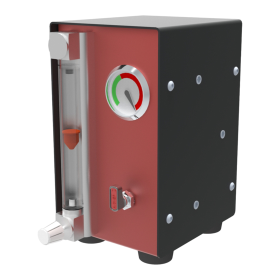
4.0 Product Overview Part Identification 1 Flowmeter 2 Flowmeter Adjustment Knob 3 Foot 4 Gas Control Valve 5 Pressure Indicator 6 Gas Outlet 7 Gas Inlet 8 Back Panel Solenoid Valve Relay Connection (Advanced Gas Package Only) -
Page 9: Input / Output Identification
Product Labels Before commissioning this product, ensure that the following product information and warning labels are in the positions detailed below: 1 Carbolite Gero Logo 2 Gas Selector Positioning Label 3 Gas Outlet Label 4 Solenoid Valve Relay Connection Label (Advanced Gas Package Only) -
Page 10: Specifications
Specifications Inert Gas Package (Single Box) Height x Width x Depth (mm) 240 x 135 x 215 Approximate Weight (kg) Electrical Specifications (Advanced Gas Package Only) The advanced gas package has a 24 Volt DC power connection via the solenoid valve relay. -
Page 11: Installation
5.0 Installation Changing Flowmeter Scales The inert gas boxes are supplied with a set of interchangeable gas scale inserts to allow the flowmeter modules to be used with a range of gases. Note: The customer is responsible for selecting and installing the correct scale for the intended gas. - Page 12 Carefully remove the glass case as shown. Select the correct gas scale insert for the flowmeter module and fold it around the glass tube, as shown. Insert the scale into the flowmeter, then refit the glass case to hold it in position.
-
Page 13: Connecting Flowmeter Modules
Secure the glass case in place by twisting the metal tabs at either end of the flowmeter by 90°, returning them to their original positions. Connecting Flowmeter Modules When using more than one gas box, it is recommended that the boxes are secured together to reduce the risk of any interconnecting gas pipes being pulled loose. - Page 14 Insert the three spacers and screws provided into the threads in the outer casing. Push the two flowmeter mod- ules together until the screws on the side of one module locate into the keyhole slots on the other module. Remove the screw securing the back panel of the flowmeter module on the left (when viewed from the rear).
-
Page 15: Gas Connections
Remove the back panel. Tighten the three hexhead screws entering through the key- hole slots to secure the two flow- meter modules together, taking care not to damage any internal tubes or fittings. Replace the back panel. Gas Connections 5.3.1 Gas Inlet The gas inlet comprises a 6mm outside diameter fitting, into which an appro- priately sized hose can be pushed. -
Page 16: Gas Outlet To Vessel
5.3.2 Gas Outlet to Vessel 1 Gas Outlet 2 Push-in T-Fitting 3 Blanking Plug 4 6mm Male Connector 5 6mm T-Connector 6 Pressure Relief Valve 7 6mm Braided Hose 8 6mm Union Note: Parts 2, 3, 4, 5 and 6 are supplied as an assembly. If not already connected, screw the T-fitting, and the connected assembly, onto the gas outlet at the rear of the gas box, carefully tightening it with an appropriate sized spanner. -
Page 17: Connecting Multiple Gas Boxes
5.3.3 Connecting Multiple Gas Boxes Up to 3 gas boxes can be connected together in order to supply a mixture of gases into the vessel. Additional boxes will be supplied with a Y-fitting (two inlets on top) to accommodate interconnecting pipes between the boxes. Fully insert the interconnecting pipes into the top of the Y and T-fit- tings as shown in the image below. - Page 18 Push the solenoid connector socket onto the terminals on the back of the gas box, and secure it in place by tight- ening the screw on the rear of the socket. Push the relay connector at the other end of the cable into the cor- responding relay port on the back of the product control box.
-
Page 19: Basic Operation
6.0 Basic Operation Before introducing the gas supply through the gas box ensure the gas control valve on the front of the gas box is turned off; the gas control valve should be in the horizontal position. Note: The gas pressure is controlled at the gas source not by the gas box. -
Page 20: Gases And Flow Rates
When the gas is flowing, turn the adjustment knob on the flowmeter to set the desired gas flow rate. Note: If using the Advanced gas box, the gas will only flow when the solenoid valve is activated. Check that the correct gas flow rates are set. The reading should be taken from the top of the float so that the flat edge is level with the increments on the gas scale. - Page 21 98% Argon (Ar) / 2% Hydrogen (H 1 - 9 Carbon Dioxide (CO 1 - 8.5 Helium (H 2 - 20...
-
Page 22: Maintenance
7.0 Maintenance General Maintenance Preventive rather than reactive maintenance is recommended. The type and frequency depends on the product use; the following are recommended. Maintenance Schedule CUSTOMER QUALIFIED PERSONNEL Frequency Maintenance Method Procedure Daily Weekly Monthly Annually Annually Safety Check gas lines for any moisture, block- Maintain clean gas lines ages or leakages. -
Page 23: Decommissioning, Storage And Disposal
Within the European Community the disposal of electrically operated devices is regulated according to guidance based on the EU Directive 2012/19/EU on Waste Electrical and Electronic Equipment (WEEE). Disposal regulations may differ worldwide. If uncertain, please contact Carbolite Gero for advice on disposal. - Page 25 Notes Service Record Engineer Name Date Record of Work...
- Page 26 The products covered in this manual are only a small part of the wide range of ovens, chamber furnaces and tube furnaces manufactured by Carbolite Gero for laboratory and industrial use. For further details of our standard or custom built products please contact us at the address below, or ask your nearest stockist.
Need help?
Do you have a question about the CARBOLITE GERO and is the answer not in the manual?
Questions and answers