Table of Contents
Advertisement
Quick Links
Advertisement
Table of Contents

Subscribe to Our Youtube Channel
Related Manuals for Zeta Alarm Systems ZT-20EX

Summary of Contents for Zeta Alarm Systems ZT-20EX
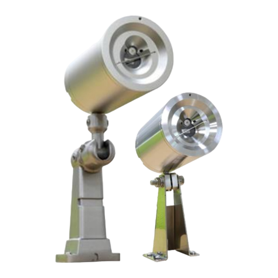
- Page 1 Flame Detectors Model: ZT-20EX / ZT-500EX User Guide 47-153 / 47-154 , Rev. A, Aug 15, 2019 Zeta Alarms Limited Detection House, 72-78 Morfa Road, Swansea, SA1 2EN, United Kingdom Phone: +44(0)1792 455175 Fax: +44(0)1792 455176 Website: www.zetaalarmsystems.com Email: info@zetaalarmsystems.com...
-
Page 3: Table Of Contents
User Guide of ZT-20EX & ZT-500EX <User Guide of ZT-20EX & ZT-500EX> TABLE OF CONTENTS <User Guide of ZT-20EX & ZT-500EX> ............. 3 Unpack & Checking contents ............... 4 Internal Wire Cabling & DIP SW setting ..........5 Installation ..................7 Operation .................. -
Page 4: Unpack & Checking Contents
47-153 / 47-154 , Rev. A, Aug 15, 2019 1 Unpack & Checking contents Unpack the delivered pack and check the following contents. Quick Start Guide /Other Notes Detector Ex Cable Gland (*Optional) Coupler (*Optional) 2-meter Cable Wires (*Optional) Swivel Mount Screws for Label... -
Page 5: Internal Wire Cabling & Dip Sw Setting
User Guide of ZT-20EX & ZT-500EX 2 Internal Wire Cabling & DIP SW setting 1). Loose the 3(three) socket-head cap screws of back cover and separate the back cover from the middle cover, as follows. At this time, the internal connection harness (connecting the internal circuit boards) may be inevitably removed. -
Page 6: Figure 4. Connecting Wires & Securing The Cable Gland
47-153 / 47-154 , Rev. A, Aug 15, 2019 Secure tightly for water-proof (*Optional) Figure 4. Connecting Wires & Securing the cable gland 5). Plug the end of removed connection harness first into the relevant connector on PCB of middle cover and then, into the relevant connector on PCB of back cover. 6). -
Page 7: Installation
User Guide of ZT-20EX & ZT-500EX 3 Installation The detector can be mounted on the wall with either of two kinds of Swivel Mounts, (TM-AL10 in aluminum and TM-ST10 in SS316) which are optionally selectable by customers when ordering the detector. -
Page 8: Operation
47-153 / 47-154 , Rev. A, Aug 15, 2019 the area is unobstructed. Secure the detector in that position by tightening the locking screws on the Swivel mount. The detector is now correctly located, aligned and ready to be connected to the system. 4 Operation Once powered up, the detector will begin appr. -
Page 9: Table 2. Dip Switch Settings
User Guide of ZT-20EX & ZT-500EX Table 2. DIP Switch Settings :ON “(1)” :OFF ”(0)” 1 2 3 4 5 6 7 8 (OFF) DIP Switch Position No. Mode Selections Sensitivity Range (1) OFF-OFF(00) : Highest OFF-ON(01) : High ON-OFF(10) : Medium<default>... -
Page 10: Table 3. Output Interface Of Connection Pcb
47-153 / 47-154 , Rev. A, Aug 15, 2019 performing a manual BIT). Latching affects the ALARM RELAY, 4-20mA output, the ALARM LED. (4). The detector has a selectable option over alarm relay initialization between normally open, N.O. (as Default) and normally closed, N.C. Table 3. -
Page 11: Figure 9. Typical 4-Wiring For Relay Contact Output
User Guide of ZT-20EX & ZT-500EX Power Supply Detector Detector Last Detector (RED) (RED) DC24V(+) (BLACK) (BLACK) Return(-) Control Panel (WHITE /YELLOW) (WHITE/YELLOW) (YELLOW) Alarm(N.O/N.C) (GREEN (GREEN/BLUE) (BLUE) /BLUE) Alarm(N.O/N.C) EQL Box (ex:10 ㏀) Figure 9. Typical 4-Wiring for Relay Contact Output Notes: 1. -
Page 12: Figure 10. 4-20Ma Output Jumper Placement
47-153 / 47-154 , Rev. A, Aug 15, 2019 Figure 10. 4-20mA Output Jumper Placement... -
Page 13: Figure 11. 4-20Ma Source And Sink
User Guide of ZT-20EX & ZT-500EX Note the INT and ISO Jumper position for each configuration. Detector Non-Isolated configuration(Source) Detector Non-Isolated configuration(Sink) 24VDC 24VDC Panel Panel Detector Detector +VDC 24VDC(+) +VDC 24VDC(+) 24VDC(-) 24VDC(-) -VDC -VDC 4-20mA 4-20mA 4-20mA 4-20mA ○... -
Page 14: Technical Specification
Detector Last Detector Power Supply DC24V(+) Return(-) Control Panel RS485 COMPUTER PORT Figure 12. RS-485 Networking 5 Technical Specification ZT-20EX (UV/IR) ZT-500EX (IR3) GENERAL SPECIFICATION Spectrum Response UV/IR (Dual Bands) Triple IR bands Detection Range Fuel Distance Fuel Distance n-Heptane... - Page 15 User Guide of ZT-20EX & ZT-500EX SPST volt-free contacts rated 5A at 30VDC or 250VAC 0-20mA (stepped) Source & Sink, Isolated/Non-isolated configuration Fault: 0 +1mA Normal: 4mA±10% Warning: 16mA±5% Alarm: 20mA±5% Resistance Loop : max. 500Ω RS-485 Modbus compatible communication link that RS-485 <optional>...
Need help?
Do you have a question about the ZT-20EX and is the answer not in the manual?
Questions and answers