Sony DSR-80 Service Manual
Digital videocassette recorder
Hide thumbs
Also See for DSR-80:
- Brochure & specs (8 pages) ,
- Operating instructions manual (88 pages) ,
- Installation manual (26 pages)
Advertisement
Quick Links
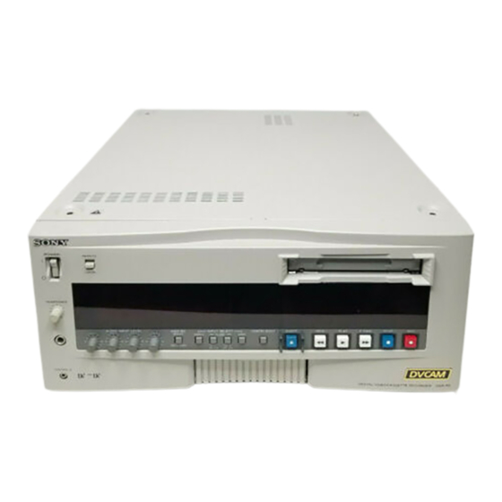
DIGITAL VIDEOCASSETTE RECORDER
DSR-80/80P
DIGITAL VIDEOCASSETTE PLAYER
DSR-60/60P
SDI OUTPUT BOARD
DSBK-100
DSBK-100P
QSDI OUTPUT BOARD
DSBK-110
DSBK-110P
SDI INPUT/OUTPUT BOARD
DSBK-120
DSBK-120P
TIME CODE INPUT/OUTPUT BOARD
DSBK-130
DSBK-130P
SERVICE MANUAL
Vol. 1 (1st Edition/Revised 2)
Advertisement


Need help?
Do you have a question about the DSR-80 and is the answer not in the manual?
Questions and answers