Table of Contents
Advertisement
Quick Links
Advertisement
Table of Contents

Subscribe to Our Youtube Channel
Related Manuals for EXFO Optical Explorer


Summary of Contents for EXFO Optical Explorer
- Page 1 User Guide Optical Explorer www.EXFO.com...
- Page 2 EXFO Inc. (EXFO). Information provided by EXFO is believed to be accurate and reliable. However, no responsibility is assumed by EXFO for its use nor for any infringements of patents or other rights of third parties that may result from its use.
-
Page 3: Table Of Contents
Contents Contents Regulatory Information ......................vii 1 Introducing the OX1 Optical Explorer ............1 Main Features .........................2 Available Options ........................5 LED Indicator Description .......................7 Battery Status Icon Description ....................8 Power Sources ........................8 Test Functions and Tools .......................10 Using Your OX1 as a Standalone Unit ...................11 Using Your OX1 With a Smart Device ...................11... - Page 4 Configuring Sleep Mode .......................52 Selecting Test Wavelengths ....................54 Enabling or Disabling Power Measurements .................59 Working With Custom Pass/Fail Thresholds or EXFO Advisor ..........64 Working With the PON Tool ....................72 Working With a Demarcation Section ...................78 Configuring the IOR Value ....................86 Reverting to Factory Settings ....................89...
- Page 5 Sharing Information With the Technical Support Group .............221 Viewing System Information ....................224 Transportation ........................225 12 Warranty ....................227 General Information ......................227 Gray Market and Gray Market Products ................228 Liability ..........................229 Exclusions ...........................229 Certification ........................229 Service and Repairs ......................230 EXFO Service Centers Worldwide ..................231 Optical Explorer...
- Page 6 Contents A Installing the Hand Strap .................233 Index .......................237...
-
Page 7: Regulatory Information
Electronic test and measurement equipment is exempt from FCC part 15, subpart B compliance in the United States of America and from ICES-003 compliance in Canada. However, EXFO Inc. makes reasonable efforts to ensure compliance to the applicable standards. The limits set by these standards are designed to provide reasonable protection against harmful interference when the equipment is operated in a commercial environment. - Page 8 Regulatory Information General Wireless Compliance Related Information Your unit comes with an internal wireless module (adapter) and two antennas for which the information hereafter applies: This product does not contain any wireless user-serviceable components. Any unauthorized product changes or modifications will invalidate warranty and all applicable regulatory certifications and approvals.
- Page 9 : Channels 1 through 11 - Between the frequencies 2412 MHz - 2462 MHz. The output power is 11.7 dBm typical. Wi-Fi: Channels 1 through 11 - Between the frequencies 2412 MHz - 2462 MHz. The maximum output power is 18.5 dBm. Optical Explorer...
- Page 10 Regulatory Information European Wireless Compliance Related Information ® Your unit is designed to operate in the Bluetooth and WLAN 2.4 GHz bands. ® The information about the Bluetooth and Wi-Fi frequency bands is as follows: ® Bluetooth : Channels 1 through 13 - Between the frequencies 2412 MHz - 2472 MHz.
- Page 11 European Declaration of Conformity Hereby, EXFO declares that the radio equipment type “OX1” is in compliance with European Directive 2014/53/EU. The full text of the EU declaration of conformity is available at the following Internet address: www.exfo.com/en/resources/legal-documentation.
- Page 12 Regulatory Information Japan Wireless Compliance Related Information ® Your unit is designed to operate in the Bluetooth and WLAN 2.4 GHz bands. ® The information about the Bluetooth and Wi-Fi frequency bands is as follows: ® Bluetooth : Channels 1 through 13 - Between the frequencies 2412 MHz - 2472 MHz.
-
Page 13: Introducing The Ox1 Optical Explorer
40 km) optical links and their components. It is particularly well suited for installation and repair jobs. It can work in association with a smart device equipped with the EXFO TestFlow mobile application allowing you to document the test results, archive them, and generate reports. -
Page 14: Main Features
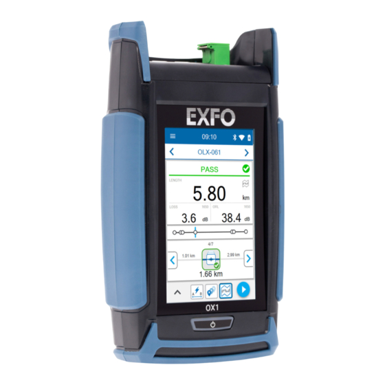
Easy detection and location of common causes of failure with the Fault Xplorer™ function Quality evaluation of the installations with EXFO Advisor™. Measurements are rated using a five-star system. PDF report creation Job management and cloud storage... - Page 15 Introducing the OX1 Optical Explorer Main Features Front panel Holes for the hand strap Optical port (Pro unit with Click-Out optical connector shown) Laser radiation emitted at this port when laser is active. Touchscreen Power (on/off) button (also serves as battery status LED)
- Page 16 Introducing the OX1 Optical Explorer Main Features Top panel Optical port (Pro unit with Click-Out optical connector shown) USB 2.0 Type-C connector for battery charging (see Power Bottom panel Sources on page 8)
-
Page 17: Available Options
Introducing the OX1 Optical Explorer Available Options Available Options Several options are available for the Optical Explorer: Option Description Optical Explorer designed for the maintenance of live fibers 1650 nm +10 nm, filtered PRO-M Optical Explorer Pro designed for the maintenance... - Page 18 Introducing the OX1 Optical Explorer Available Options Option Description Optical Explorer designed for installation or repair of dark fibers 1310/1550 nm ±30 nm PRO-I Optical Explorer Pro designed for installation or repair of dark fibers 1310/1550 nm ±30 nm Click-Out optical connector...
-
Page 19: Led Indicator Description
Introducing the OX1 Optical Explorer LED Indicator Description LED Indicator Description The power button, located on the front panel of your unit, also serves as a LED indicator providing you with information about the battery status. Unit Status Meaning Connected to an Blue The battery is fully charged. -
Page 20: Battery Status Icon Description
A flash symbol indicates that the unit is connected to an external power source. Power Sources The Optical Explorer operates with the following power sources: Indoor use only: USB power adapter connected to a power outlet (fastest way to charge the battery). - Page 21 Introducing the OX1 Optical Explorer Power Sources Note: If you have a vehicle equipped with dedicated USB charging ports, you could connect your unit to one of these ports to charge the battery. The actual results will vary with each vehicle. You could also use a certified USB power bank (portable charger) to charge your unit.
-
Page 22: Test Functions And Tools
Introducing the OX1 Optical Explorer Test Functions and Tools Test Functions and Tools Your Optical Explorer offers functions and tools to help you with common testing situations such as fiber break location, optical link verification, identification and location of common causes of networks failure. -
Page 23: Using Your Ox1 As A Standalone Unit
(single or multiple measurements). See Working With the TestFlow Mobile Application on page 135. Technical Specifications To obtain this product’s technical specifications, visit the EXFO Web site at www.exfo.com. Optical Explorer... -
Page 24: Conventions
Introducing the OX1 Optical Explorer Conventions Conventions Before using the product described in this guide, you should understand the following conventions: ARNING Indicates a potentially hazardous situation which, if not avoided, could result in death or serious injury. Do not proceed unless you understand and meet the required conditions. -
Page 25: Safety Information
ARNING Use only accessories designed for your unit and approved by EXFO. For a complete list of accessories available for your unit, refer to its technical specifications or contact EXFO. - Page 26 General Safety Information MPORTANT Refer to the documentation provided by the manufacturers of any accessories used with your EXFO product. It may contain environmental and/or operating conditions limiting their use. MPORTANT When you see the following symbol on your unit...
-
Page 27: Other Safety Symbols On Your Unit
Direct current Alternating current The unit is equipped with an earth (ground) terminal. The unit is equipped with a protective conductor terminal. The unit is equipped with a frame or chassis terminal. On (Power) Off (Power) On/off (Power) Fuse Optical Explorer... -
Page 28: Laser Safety Information
Safety Information Laser Safety Information Laser Safety Information Your instrument is in compliance with standard IEC 60825-1: 2014. ARNING Viewing the laser output with telescopic optical instruments (for example, telescopes and binoculars) may pose an eye hazard and thus the user should not direct the beam into an area where such instruments are likely to be used. - Page 29 Max. peak power: / Puissance crête maximum : ≤ 100 mW Wavelength: / Longueur d’onde : 1600 nm-1700 nm Pulse width: / Largeur de l’impulsion : ≤ 20 μs Max. peak power: / Puissance crête maximum : ≤ 150 mW Optical Explorer...
-
Page 30: Electrical Safety Information
ES1 circuits only. Use only the listed and certified USB power adapter provided by EXFO with your unit. It provides reinforced insulation between primary and secondary, and is suitably rated for the country where the unit is sold. - Page 31 95 °F) Relative humidity unit: ≤ 93 % non-condensing USB power adapter: 10 % to 90 % non-condensing Maximum operation altitude 2000 m (6562 ft) (unit connected to external power source) 5000 m (16405 ft) (unit operated from battery) Optical Explorer...
- Page 32 Safety Information Electrical Safety Information Equipment Ratings Pollution degree 2 (unit connected to external power source) 3 (unit operated from battery) Overvoltage category unit: I USB power adapter: II Measurement category Not rated for measurement categories II, III, or IV Input power unit: 5 V ;...
-
Page 33: Getting Started With Your Unit
Turning on Your Unit When you turn on the unit for the very first time, a wizard is displayed, enabling you to set the operation language, read and accept the EXFO license agreement, and set other regional settings (see the section about the first startup for more information). -
Page 34: Turning Off Your Unit
Getting Started with Your Unit Turning off Your Unit Turning off Your Unit Unless specified otherwise in this documentation, the settings you configure on your unit are kept in memory even when you turn the unit off. There are several ways to turn off the unit, including the following: Sleep: keeps the unit’s status information in memory (RAM). -
Page 35: Configuring Your Unit At First Startup
If you select a language other than English, the unit will restart automatically to apply the change. 3. Read and accept the EXFO license agreement, then tap NEXT. 4. Follow the on-screen instructions to configure the other regional parameters and view the getting started guide. -
Page 36: Understanding Fiber Xplorer
Getting Started with Your Unit Understanding Fiber Xplorer™ Understanding Fiber Xplorer™ Fiber Xplorer can be seen as the starting point of the application. You can perform measurements in one of the test functions and navigate through the results. It provides information on many elements such as the ®... - Page 37 Bluetooth ® , Wi-Fi, and battery Number of pending To view next notifications measurement Three-line menu to access tools and options To view previous measurement Pass/Fail status or EXFO Advisor verdict Function used to take a measurement Link results Optical Explorer...
- Page 38 Getting Started with Your Unit Understanding Fiber Xplorer™ Link overview Distance to the next element To view previous element Link view Distance to the previous To view next element element To start or stop a measurement (the button turns to a red stop button). To show the drawer and access measurement-related parameters Link Mapper function...
-
Page 39: Viewing Notifications
The notification related to the optical output diagnosis can only be erased when the result of the verification is pass. Note: The notification of the failed diagnosis is kept in memory even if you revert to factory settings. You can delete a notification when it has been read. Optical Explorer... - Page 40 Getting Started with Your Unit Viewing Notifications To view notifications: 1. From the main menu, tap Notifications. The pending notifications are displayed in a list. 2. You can delete the notification you have read with the X. 3. When the unit prompts you, tap YES.
-
Page 41: Working With Launch And Receive Test Cords
For easier handling and optimum performance when you work with launch and receive cords, EXFO strongly recommends to use the cords especially designed by EXFO for your OX1 unit. However, you can use your own test cords. By default, the use of launch and receive cords is disabled, but you can enable it and specify the lengths of the cords you intend to use. - Page 42 Getting Started with Your Unit Working With Launch and Receive Test Cords To configure the launch and receive cords lengths from the Settings page: 1. From the main menu, tap Settings.
- Page 43 Getting Started with Your Unit Working With Launch and Receive Test Cords 2. From the Optical Explorer section, tap Test cords. 3. To configure the launch and receive cords settings, proceed as follows: 3a. If necessary, activate the feature with the corresponding toggle.
- Page 44 Getting Started with Your Unit Working With Launch and Receive Test Cords 3c. Select the length of the cable you want to use for your measurement. If you have selected Custom, enter the length with the numeric keypad. To change the distance units 3d.
- Page 45 Xplorer: 1. From Fiber Xplorer, tap the arrow to access the drawer. 2. Tap Test cords. 3. To configure the launch and receive cords settings, proceed as follows: 3a. If necessary, activate the feature with the corresponding toggle. Optical Explorer...
- Page 46 Getting Started with Your Unit Working With Launch and Receive Test Cords 3b. Under the desired test cord, tap the displayed length to edit it. 3c. Select the length of the cable you want to use for your measurement. If you have selected Custom, enter the length with the numeric keypad.
-
Page 47: Cleaning And Connecting Optical Fibers
To ensure maximum power and to avoid erroneous readings: Always inspect fiber ends and make sure that they are clean as explained below before inserting them into the port. EXFO is not responsible for damage or errors caused by bad fiber cleaning or handling. - Page 48 EXFO uses good quality connectors in compliance with EIA-455-21A standards. To keep connectors clean and in good condition, EXFO strongly recommends inspecting them with a fiber inspection scope (or probe) before connecting them. Failure to do so may result in permanent damage...
-
Page 49: Temperature Management
(see Equipment Ratings on page 19). Avoid leaving your unit in an overheated vehicle. You may have to let your unit cool down before being able to use it. Ensure that your unit is normally protected from direct sunlight (during use and storage). Optical Explorer... -
Page 51: Setting Up Your Unit
You may also want to reduce the display brightness to save battery power (the higher the brightness level, the higher the power consumption). The brightness value is kept in memory even when you turn the unit off. To adjust the display brightness: 1. From the main menu, tap Settings. Optical Explorer... -
Page 52: Enabling Or Disabling Sound Notifications
This sound varies with the type of notification, which means that you will hear a different sound in each of these situations: At the end of a measurement performed using EXFO Advisor thresholds. At the end of a measurement performed using custom thresholds when its status is Pass. - Page 53 Setting up Your Unit Enabling or Disabling Sound Notifications To enable or disable the sound notifications on your unit: 1. From the main menu, tap Settings. 2. Scroll down to the Device settings section. Optical Explorer...
- Page 54 Setting up Your Unit Enabling or Disabling Sound Notifications 3. With the Sounds toggle, enable or disable the sound notifications. The new value is taken into account immediately.
-
Page 55: Selecting The Language Of Operation
English is the default language. The value is kept in memory even when you turn the unit off. To select a new interface language: 1. From the main menu, tap Settings. 2. Scroll down to the Device settings section. Optical Explorer... - Page 56 Setting up Your Unit Selecting the Language of Operation 3. Tap Language. 4. Select the desired language from the list. 5. Your unit will need to restart to complete the change of language. When the unit prompts you, confirm with OK.
-
Page 57: Adjusting The Date, Time And Time Zone
You can disable the automatic synchronization if you prefer. To modify the date format: 1. From the main menu, tap Settings. Optical Explorer... - Page 58 Setting up Your Unit Adjusting the Date, Time and Time Zone 2. Scroll down to the Device settings section. 3. Tap Date and time. 4. With the Use 24-hour format toggle, enable or disable the option, depending on your preference. If you prefer to view the time in a 12-hour (AM/PM) format, ensure that the Use 24-hour format option is disabled.
- Page 59 Adjusting the Date, Time and Time Zone To enable or disable the synchronization of date, time and time zone with the TestFlow mobile application: 1. From the main menu, tap Settings. 2. Scroll down to the Device settings section. 3. Tap Date and time. Optical Explorer...
- Page 60 Setting up Your Unit Adjusting the Date, Time and Time Zone 4. With the Sync time zone toggle, enable or disable the synchronization of date and time with the TestFlow mobile application. To adjust the date, time or time zone manually: 1.
- Page 61 3. Tap Date and time. 4. Tap the element corresponding to the value that you want to modify. 5. Modify the settings according to your needs, and then tap OK to confirm, when applicable. The new values are taken into account immediately. Optical Explorer...
-
Page 62: Selecting The Distance Units
Setting up Your Unit Selecting the Distance Units Selecting the Distance Units You can select the measurement units that your unit will use to display distance and length values. By default, the unit uses metric distance units (meters and kilometers), but you can change for imperial units (feet and kilofeet) if you prefer. - Page 63 Setting up Your Unit Selecting the Distance Units 2. Scroll down to the Device settings section. 3. Tap Distance units. 4. Select the desired distance units. The new value is taken into account immediately. Optical Explorer...
-
Page 64: Configuring Sleep Mode
Setting up Your Unit Configuring Sleep Mode Configuring Sleep Mode To help you get the optimum performance out of your unit, it comes with a predefined set of parameters to manage power. When you do not use your unit for a while, it will go into sleep mode automatically to save power (see Turning off Your Unit on page 22). - Page 65 Setting up Your Unit Configuring Sleep Mode To configure the duration after which the unit enters sleep mode: 1. From the main menu, tap Settings. 2. Scroll down to the Device settings section. 3. Tap Sleep. Optical Explorer...
-
Page 66: Selecting Test Wavelengths
Setting up Your Unit Selecting Test Wavelengths 4. Select the desired number of minutes. The new value is taken into account immediately. Selecting Test Wavelengths You can select the wavelengths you want to use for your measurements or let the unit select the most appropriate wavelengths. The manual or automatic selection of the wavelengths is kept in memory when you turn off the device as well as the wavelengths you have chosen. - Page 67 Setting up Your Unit Selecting Test Wavelengths To select test wavelengths from the Settings page: 1. From the main menu, tap Settings. 2. Under Optical Explorer, tap Wavelengths. Optical Explorer...
- Page 68 Setting up Your Unit Selecting Test Wavelengths 3. If you want to let the unit select the most appropriate wavelengths, use the Auto toggle to enable the option. If you prefer to choose the wavelengths yourself, ensure that the Auto option is deactivated (use the toggle if necessary), and then select the wavelengths you want to use for your tests.
- Page 69 Setting up Your Unit Selecting Test Wavelengths To select test wavelengths from Fiber Xplorer: 1. From Fiber Xplorer, tap the arrow to access the drawer. 2. Tap Wavelengths. Optical Explorer...
- Page 70 Setting up Your Unit Selecting Test Wavelengths 3. If you want to let the application select the most appropriate wavelengths, use the Auto toggle to enable the option. If you prefer to choose the wavelengths yourself, ensure that the Auto option is deactivated (use the toggle if necessary), and then select the wavelengths you want to use for your tests.
-
Page 71: Enabling Or Disabling Power Measurements
Note: Should the unit receive atypical signals, the suggested types of channels could differ from your actual network configuration. In this case, you could simply manually select the pair of wavelengths corresponding to your testing needs. Optical Explorer... - Page 72 Setting up Your Unit Enabling or Disabling Power Measurements The value is displayed in the Fiber Xplorer page as soon as you start an acquisition. Optical power of a link Optical power of a link (automatic PON detection selected) Once the measurement is complete, the power value is also displayed in the Link details page.
- Page 73 Setting up Your Unit Enabling or Disabling Power Measurements To enable or disable power measurements: 1. From the main menu, tap Settings. Optical Explorer...
- Page 74 Setting up Your Unit Enabling or Disabling Power Measurements 2. Under Optical Explorer, activate the feature with the toggle button, and then tap Power measurement to display the wavelengths available.
- Page 75 3. In the Power measurement page, select the desired wavelength. If you are working with a dual-channel unit, you can also select a pair of wavelengths. If you prefer to let the unit interpret the received signals (power) for your network automatically, select Detect PON. Optical Explorer...
-
Page 76: Working With Custom Pass/Fail Thresholds Or Exfo Advisor
It is displayed in the Link Results area and it can be pass, fail, or unknown. See Working With Link Results on page 96 for details. You can also let EXFO Advisor rate the quality of the results. The rating ranges from zero to five stars (half stars are possible). - Page 77 Setting up Your Unit Working With Custom Pass/Fail Thresholds or EXFO Advisor To configure custom thresholds or select EXFO Advisor from the Settings page: 1. From the main menu, tap Settings. Optical Explorer...
- Page 78 Setting up Your Unit Working With Custom Pass/Fail Thresholds or EXFO Advisor 2. Under Optical Explorer, tap Pass/Fail criteria. 3. If you want to let the application rate the quality of the results, select EXFO Advisor. If you prefer to customize the values of the thresholds, select Custom...
- Page 79 Setting up Your Unit Working With Custom Pass/Fail Thresholds or EXFO Advisor 4. To edit the threshold values, proceed as follows: 4a. If necessary, activate the threshold with the toggle button. 4b. Tap the threshold you want to modify. Optical Explorer...
- Page 80 Setting up Your Unit Working With Custom Pass/Fail Thresholds or EXFO Advisor 4c. Enter a new value. 4d. Tap OK to return to the Pass/Fail criteria page. The new thresholds are taken into account for the next measurement.
- Page 81 Setting up Your Unit Working With Custom Pass/Fail Thresholds or EXFO Advisor To configure custom thresholds or EXFO Advisor from Fiber Xplorer: 1. From Fiber Xplorer, tap the arrow to access the drawer. 2. Tap Pass/Fail criteria. Optical Explorer...
- Page 82 Setting up Your Unit Working With Custom Pass/Fail Thresholds or EXFO Advisor 3. If you want to let the application rate the quality of the results, select EXFO Advisor. If you prefer to customize the values of the thresholds, select Custom thresholds.
- Page 83 Setting up Your Unit Working With Custom Pass/Fail Thresholds or EXFO Advisor 4b. Tap the threshold you want to modify. 4c. Enter a new value. 4d. Tap OK to return to the Pass/Fail criteria page. Optical Explorer...
-
Page 84: Working With The Pon Tool
Setting up Your Unit Working With the PON Tool Working With the PON Tool The PON tool has been designed and optimized to work with specific use cases related to the FTTx architecture. With this tool, you can perform splitter detection tests (from the ONT to the splitter) and ONT detection tests (from the splitter to the ONT). - Page 85 Setting up Your Unit Working With the PON Tool Indicates a splitter detection test acquisition Indicates an ONT detection test acquisition To start an acquisition with the splitter detection test To start an acquisition with the ONT detection test Optical Explorer...
- Page 86 To configure the PON tool: 1. From the main menu, tap Settings. 2. Under Optical Explorer, activate the feature with the toggle button and tap PON tool. Note: If you do not see PON tool in the settings, it means that your current OX1...
- Page 87 Note: When working with cascaded splitters, you should always select the splitter ratio of the splitter which is closer to the location where you perform an acquisition. If the distance between both levels of splitters does not fit within the minimal length specifications, the splitter detection will fail. Optical Explorer...
- Page 88 Setting up Your Unit Working With the PON Tool 5. If you want to be able to access the PON tool settings directly from the drawer, select the Show in drawer check box. To configure the PON tool from Fiber Xplorer: 1.
- Page 89 Note: When working with cascaded splitters, you should always select the splitter ratio of the splitter which is closer to the location where you perform an acquisition. If the distance between both levels of splitters does not fit within the minimal length specifications, the splitter detection will fail. Optical Explorer...
-
Page 90: Working With A Demarcation Section
Setting up Your Unit Working With a Demarcation Section Working With a Demarcation Section Note: You can only use this feature with the Fault Xplorer and Link Mapper test functions. You can define a demarcation section when you need to validate the loss over a portion of the link. - Page 91 Setting up Your Unit Working With a Demarcation Section To set the demarcation section thresholds from the Settings page: 1. From the main menu, tap Settings. Optical Explorer...
- Page 92 Setting up Your Unit Working With a Demarcation Section 2. Under Optical Explorer, tap Pass/Fail criteria. 3. Ensure that Custom thresholds is selected.
- Page 93 Setting up Your Unit Working With a Demarcation Section 4. If necessary, activate the threshold group with the toggle button and tap Demarcation section to modify the parameters. Optical Explorer...
- Page 94 Setting up Your Unit Working With a Demarcation Section 5. Modify the thresholds as follows: 5a. Tap the threshold that you want to modify. 5b. Enter a new value. 5c. Tap OK to return to the Demarcation section page. 6. Use the Allow link < demarcation toggle button to define the behavior of the unit when it detects the end of the link before the end of the demarcation.
- Page 95 Setting up Your Unit Working With a Demarcation Section To set the demarcation section thresholds from Fiber Xplorer: 1. From Fiber Xplorer, tap the arrow to access the drawer. 2. Tap Pass/Fail criteria. 3. Ensure that Custom thresholds is selected. Optical Explorer...
- Page 96 Setting up Your Unit Working With a Demarcation Section 4. To edit the demarcation section, proceed as follows: 4a. If necessary, activate the threshold with the toggle button and tap Demarcation section to modify different parameters.
- Page 97 To have the last event identified as the actual end of fiber (Pass), enable the feature. To have the last event identified as a fiber break (Fail), disable the feature. The new thresholds will be taken into account for the next measurement. Optical Explorer...
-
Page 98: Configuring The Ior Value
Setting up Your Unit Configuring the IOR Value Configuring the IOR Value Having the proper index of refraction (IOR) is crucial for all measurements associated with distance (element position, total length, etc.). By doing so, you ensure that the distances are more accurate for your measurements. You can edit the IOR value associated with the 1550 nm wavelength only. - Page 99 Setting up Your Unit Configuring the IOR Value 2. Under Optical Explorer, tap IOR (@1550 nm). Optical Explorer...
- Page 100 Setting up Your Unit Configuring the IOR Value 3. Enter the new value. Resets the value to factory settings. 4. Tap OK to confirm the new value and return to the Settings page. The new value will be taken into account for the next measurement.
-
Page 101: Reverting To Factory Settings
OX1 to factory settings (all customized settings and erase all measurements) reset the battery indicator information once you have replaced the battery (see Replacing the Battery on page 178 for details) To revert values to factory settings: 1. From the main menu, tap Settings. Optical Explorer... - Page 102 Setting up Your Unit Reverting to Factory Settings 2. Scroll down to the Device settings section. 3. Tap Reset options. 4. Select the desired option. 5. Tap OK to confirm your choice.
-
Page 103: Testing Fibers
Very fast measurement time. For length, IL, and ORL. The link assessment is always performed using the EXFO Advisor settings. The rating displayed suggests that the link may contain faults. Fault Xplorer Fast measurement time when no problems are found on the fiber link. -
Page 104: Performing Measurements
(see Selecting Test Wavelengths on page 54 for details) the thresholds associated with the pass/fail criteria (customized or EXFO Advisor) (see Working With Custom Pass/Fail Thresholds or EXFO Advisor on page 64 for details) the length of the launch and receive test cords (see Working With... - Page 105 4. On your unit, ensure that the parameters have been set according to your needs. 5. If necessary, from the main menu, tap Fiber Xplorer. Under TestFlow, tap the name of the job you have transferred to your unit. Name of the job Optical Explorer...
- Page 106 Testing Fibers Performing Measurements 6. If you intend to perform a standard test, select a test function (see Test Functions and Tools on page 10 for details). If you intend to perform a test with the PON tool, tap the button corresponding to the test you want to perform (see Working With the PON Tool on page 72 for details).
- Page 107 See Working With Link Results on page 96, Working With Link Overview on page 98, and Working With Link View on page 99. The results are stored automatically on the unit. The application will notify you if a synchronization with the TestFlow mobile application is necessary. Optical Explorer...
-
Page 108: Working With Link Results
The ratng ranges from zero to five stars (half stars are possible). The same rating is applied to all wavelengths. If you use the EXFO Advisor thresholds in Fault Xplorer and Link Mapper, there will be no pass/fail status displayed either. - Page 109 Note: If the link ORL value is displayed with a < symbol, the value is exceeding the saturation level of the detector. Note: If the reflectance value is displayed with a > symbol, the value is exceeding the saturation level of the detector. Link length Optical Explorer...
-
Page 110: Working With Link Overview
Testing Fibers Working With Link Overview Working With Link Overview This graphic representation shows the entire link, all of its faults (Fault Xplorer), or all of its detectable elements (Link Mapper), from the link start (A) to the link end (B). The elements are displayed using a proportional distance. -
Page 111: Working With Link View
The splice can indicate the junction of two fiber sections, or any non-reflective loss induced by a bend or coupler, for instance. Connector The connector is used to join two fibers. Connector A Connector A corresponds to the link start. Optical Explorer... - Page 112 Testing Fibers Working With Link View Element Name Element Icon Meaning Connector B Connector B corresponds to the link end. Macrobends Macrobends can be displayed in the link view when more than one wavelength is present in the measurement. Out of range This element is displayed when the application cannot detect the end of fiber because of insufficient...
-
Page 113: Performing Tests When Light Is Detected On The Network
In both cases, if the amount of light that hits the OX1 detector is too important, the unit displays a message to notify you. Optical Explorer... -
Page 115: Using The Power Checker
Note: At any time, you can switch from local measurements (that are not part of a TestFlow job) to measurements within a TestFlow job. All the measurements are kept in memory. You can also open, in turn, the power checker and the source page. Optical Explorer... -
Page 116: Setting Thresholds
Using the Power Checker Setting Thresholds Setting Thresholds You can define thresholds to specify minimum and maximum power or loss values for each wavelength or you can apply the same thresholds to all wavelengths. You can also choose not to define any threshold values by disabling this feature. - Page 117 2. If you want to use the same threshold values for all wavelengths, select All wavelengths. If you prefer to define thresholds per wavelength, select By wavelength. 3. To edit the threshold values, proceed as follows: 3a. If necessary, activate the threshold with the toggle button. Optical Explorer...
- Page 118 Using the Power Checker Setting Thresholds 3b. Tap the displayed numbers. 3c. Enter a new value. 3d. Tap OK to return to the Power checker thresholds page. Note: You can revert to factory settings at any time by tapping Reset to default values.
- Page 119 Using the Power Checker Setting Thresholds To set power or loss thresholds from the Settings page: 1. From the main menu, tap Settings. 2. Scroll down to the Power checker section. 3. Tap Thresholds. Optical Explorer...
- Page 120 Using the Power Checker Setting Thresholds 4. If you want to use the same threshold values for all wavelengths, select All wavelengths. If you prefer to define thresholds per wavelength, select By wavelength. 5. To edit the threshold values, proceed as follows: 5a.
- Page 121 Setting Thresholds 5b. Tap the displayed numbers. 5c. Enter a new value. 5d. Tap OK to return to the Power checker thresholds page. Note: You can revert to factory settings at any time by tapping Reset to default values. Optical Explorer...
-
Page 122: Setting Reference Values On Your Power Checker
Using the Power Checker Setting Reference Values on Your Power Checker Setting Reference Values on Your Power Checker In loss measurement mode, your unit displays on screen the loss created by the fiber under test only, since it subtracts a reference value from the measured power. - Page 123 4. Tap TAKE REF. to save the current power value as the new reference. Note: The TAKE REF. button is disabled when the power value is unknown or too low and the application displays LOW or "---" on screen. Optical Explorer...
-
Page 124: Measuring Power Or Loss
Using the Power Checker Measuring Power or Loss Measuring Power or Loss Measuring absolute power or link loss is done the same way, except for the referencing step. If you are working with a dual-channel unit, you can either select a single wavelength, a pair of wavelengths, or let the unit automatically interpret the received signal(s) from your PON network, to measure power. - Page 125 If you select the automatic PON detection, you will only see the power value measured at the received wavelength. 7. Repeat the procedure for other wavelengths if desired. The absolute power or link loss value appears on screen. Optical Explorer...
-
Page 127: Using The Light Source
Note: At any time, you can switch from local measurements (that are not part of a TestFlow job) to measurements within a TestFlow job. All the measurements are kept in memory. You can also open, in turn, the power checker and the source page. Optical Explorer... - Page 128 Using the Light Source To use the light source: 1. From the main menu, tap Source. 2. Select a wavelength.
- Page 129 Using the Light Source 3. Select a modulation. MPORTANT The OX1 Optical Explorer can be used in continuous source mode (CW) to perform optical power measurements and it is compatible only with the following: high power Germanium (GeX) versions of the 300 and 600 Series, as well as any unit’s built-in GeX power...
- Page 130 Using the Light Source 4. To set the timer, proceed as follows: 4a. If necessary, activate the feature with the toggle button. Note: If you do not want to set the timer, deactivate the feature with the toggle button.
- Page 131 Using the Light Source 4b. Tap the displayed numbers. 4c. Enter the number of minutes during which you want the source to emit light. 4d. Tap OK to return to the Source page. Optical Explorer...
- Page 132 Using the Light Source 5. Tap to start the light emission. A blinking icon and a red banner clearly indicate when the light source is emitting. Indicate the source is emitting...
- Page 133 6. To avoid draining the battery of the unit, tap to stop the light emission as soon as your tests are complete. Note: If you have set the timer, the light emission stops when the value you have entered reaches zero. Optical Explorer...
-
Page 135: Managing Test Results
Once this number reaches 999, it is reset to 000 automatically. Any existing measurement bearing the same name as the new measurement is overwritten. Note: The unit will prompt you before resetting the name. Measurements are visible from their dedicated list (accessible via the main menu) and from Fiber Xplorer. Optical Explorer... - Page 136 Managing Test Results Viewing Measurements To view measurements from their dedicated list: On your unit, from the main menu, tap Measurements to view the results that are not part of a TestFlow job. Tap the name of the job to see the associated results of the tests (unit used in conjunction with a smart device).
- Page 137 Fiber Xplorer. Position indicator (not a scroll bar) Tap to switch to Fiber Pass/Fail status or EXFO Xplorer for detailed Advisor rating information. Note: The measurement appearing at the top of the list corresponds to the last measurement displayed in Fiber Xplorer.
- Page 138 Managing Test Results Viewing Measurements To view measurements from Fiber Xplorer: From Fiber Xplorer, use the arrows to view the available measurements, in turn. For more information, see Working With Link Results on page 96, Working With Link Overview on page 98, and Working With Link View on page 99.
-
Page 139: Changing An Element Type
To change an element type: 1. In the link results area, tap the element you want to modify. See Working With Link Results on page 96 for details. 2. Use the blue arrows to change the element type. Optical Explorer... - Page 140 Managing Test Results Changing an Element Type A “*” sign is displayed both in Element details and in Fiber Xplorer to indicate the change of element type. Indicates a modified element type...
-
Page 141: Deleting Measurements
This means that, for example, even if you delete the OX1-003 measurement right after it is complete, the unit will not reuse OX1-003 for the next measurement, but will use OX1-004. To delete measurements manually: 1. From the main menu, tap Measurements. Optical Explorer... - Page 142 Managing Test Results Deleting Measurements 2. Tap from the upper right corner.
- Page 143 For a quick selection of all measurements MPORTANT Deleted measurements cannot be recovered. The deletion is effective as soon as you tap DELETE (no confirmation message will be displayed). 4. Tap DELETE. The selected measurements are removed from the list. Optical Explorer...
-
Page 144: Generating Measurement Reports
2. On the smart device, if it is not already done, open the TestFlow mobile application and access the Optical Explorer tool. If the application prompts you to sign in to a TestFlow account, tap NOT NOW, since you do not need to connect to a TestFlow account to... - Page 145 Managing Test Results Generating Measurement Reports 3. From the measurements list, tap the entry corresponding to the measurement for which you want to generate a report. Three-dot menu 4. From the three-dot menu, select PDF report. Optical Explorer...
- Page 146 Managing Test Results Generating Measurement Reports 5. If desired, modify the report information by tapping the desired field. All the fields are editable, including the report title. 6. When you have finished editing the report information, tap CREATE to start the report creation. Note: As soon as the report is generated, you can transfer it with the tools available from your smart device as you would do with any other PDF file.
-
Page 147: Working With The Testflow Mobile Application
Note: Depending on the type of smart device you are using, the appearance of the Optical Explorer tool (available from the TestFlow mobile application) may vary slightly from the illustrations presented in this documentation. Unless otherwise specified, the information applies both to the Android- and iOS-based smart devices. -
Page 148: Installing The Testflow Mobile Application On Your Smart Device
From your iOS-based smart device, open the App Store (usually App Store icon). 3. From the Play Store or the App Store, search for EXFO or TestFlow Mobile to localize the TestFlow mobile application. 4. Start the installation and follow the on-screen instructions. -
Page 149: Establishing Or Closing A Connection With A Smart Device Via The Bluetooth Technology
Similarly, if a connection exists already, but you wish to connect a smart device to another OX1 unit, you can close the connection from the smart device (Optical Explorer tool in the TestFlow mobile application). - Page 150 NOT NOW, since you do not need to connect to a TestFlow account to establish the connection between your unit and a smart device. 3c. Tap the three-line icon to access the main menu. 3d. Under Tools, tap Optical Explorer.
- Page 151 Note: If the OX1 unit that you want to use is already connected to another smart device, you must first close the connection between the OX1 unit and the other smart device before being able to connect to this specific OX1. Optical Explorer...
- Page 152 Working With the TestFlow Mobile Application Establishing or Closing a Connection With a Smart Device Via the Bluetooth Technology To close the connection with a smart device from your unit: 1. From the main menu, tap Settings. 2. From the Wireless section, tap Disconnect mobile app.
-
Page 153: Enabling Or Disabling The Wireless Communication
Bluetooth technology. The interactions between your unit and the cloud server as well as the EXFO update server (to retrieve firmware and software updates), are accomplished using a connection to a wireless network. ® By default, the Bluetooth communication is enabled on your unit, but the Wi-Fi is not. - Page 154 Working With the TestFlow Mobile Application Enabling or Disabling the Wireless Communication To enable or disable the wireless communication from your unit: 1. From the main menu, tap Settings. 2. Use the Wi-Fi or Bluetooth toggle to enable or disable the communication as needed.
- Page 155 1. On the smart device, open the TestFlow mobile application and access its main menu ( menu). 2. Under Tools, tap Optical Explorer. 3. From the Optical Explorer tool, open the three-dot menu, and then select OX1 settings to access the parameters. Optical Explorer...
- Page 156 Working With the TestFlow Mobile Application Enabling or Disabling the Wireless Communication 4. Tap the Wi-Fi line. 5. Use the OX1 Wi-Fi toggle to enable or disable the Wi-Fi communication. The change is taken into account immediately.
-
Page 157: Working With A Wireless Network
You can remove configured networks from the list to prevent automatic connections to these networks. If you remove the network currently in use, the unit (or the Optical Explorer tool in the TestFlow mobile application) will try to connect to the next configured network on the list that is available. - Page 158 Working With the TestFlow Mobile Application Working With a Wireless Network With dynamic IPv4 address assignment Not secured, or secured with WPA/WPA2-Personal standards (WPA-PSK/WPA2-PSK versions) Broadcasting their network names (SSID) or not (SSID visible or hidden) Configured with a 2.4 GHz Wi-Fi band (b/g/n frequencies). Note: Your unit does not support the WEP and WPS standards.
- Page 159 The portion of the icon that appears in white (title bar) or in dark grey (list of wireless networks) reflects the strength of the signal. Password-protected (secured) networks are identified by a lock. Optical Explorer...
- Page 160 Working With the TestFlow Mobile Application Working With a Wireless Network Configuring a Wireless Network Before being able to connect your unit to a Wi-Fi network, you must first configure the desired networks directly on your unit or with the TestFlow mobile application.
- Page 161 (identified by a lock icon) Network to which the unit is currently connected or Already-configured network used during the network (garbage can icon last work session visible) Network not configured yet (no garbage can icon visible) Signal strength Optical Explorer...
- Page 162 Working With the TestFlow Mobile Application Working With a Wireless Network 5. If the network is protected by a network security key (password), enter The application establishes the communication automatically.
- Page 163 2. If necessary, enable the Wi-Fi communication on your unit (see Enabling or Disabling the Wireless Communication on page 141). 3. On the smart device, open the TestFlow mobile application and access its main menu ( menu). 4. Under Tools, tap Optical Explorer. Optical Explorer...
- Page 164 Working With the TestFlow Mobile Application Working With a Wireless Network 5. From the Optical Explorer tool, open the three-dot menu, and then select OX1 settings to access the parameters. 6. Tap the Wi-Fi line. 7. Tap the item corresponding to the wireless network that you want to configure.
- Page 165 Wi-Fi network before attempting to connect to this network from your OX1 unit. This is particularly useful in the case of secured networks to ensure that the provided password is good. Optical Explorer...
- Page 166 Working With the TestFlow Mobile Application Working With a Wireless Network Connecting to a Wireless Network From Your Unit When you start a new work session with your unit, it will automatically connect to the last network used, unless this network is not available or its password has changed in the meantime (reconfiguration necessary).
- Page 167 Note: If you select a network different than the one used during your last work session and the connection to this new network fails, the application will automatically switch to the last network used to try and establish a connection. Optical Explorer...
- Page 168 To remove a configured network from the list: 1. From your unit or from the Optical Explorer tool in the TestFlow mobile application, go to the main menu, and then tap Settings (from unit) or...
- Page 169 Working With the TestFlow Mobile Application Working With a Wireless Network Note: In the Optical Explorer tool (in TestFlow mobile application), the main menu is accessible by opening the three-dot menu. 2. Tap Wi-Fi. Optical Explorer...
- Page 170 Working With the TestFlow Mobile Application Working With a Wireless Network 3. Tap the icon corresponding to the wireless network that you want to remove. Network to which the unit is currently connected or network used during the last work session 4.
-
Page 171: Transferring A Testflow Job To The Ox1
When the current job changes, the tests that have not been performed yet on the previous job will be available the next time you switch back to this job. Note: You can only synchronize one job at a time. Optical Explorer... - Page 172 Working With the TestFlow Mobile Application Transferring a TestFlow Job to the OX1 To transfer a TestFlow job to the OX1: 1. Before being able to retrieve a job from TestFlow to transfer it to your OX1, ensure that you meet the following requirements: you have a TestFlow account or you have received an invitation from your organization to active your account you have installed the TestFlow mobile application on your smart...
- Page 173 4. When the unit prompts you, tap Sync. Note: If you are not already connected to an OX1 unit, the application will prompt you to select the unit you want to use. Note: You can also access the job sync feature from the three-dot menu. Optical Explorer...
- Page 174 Working With the TestFlow Mobile Application Transferring a TestFlow Job to the OX1 5. In the OX1, from the main menu, tap the name of the job you have just transferred. 6. Tap the test you want to perform. Note: From the main menu, you can tap TestFlow to go directly to the next test you have to perform.
-
Page 175: Configuring The Unit's Behavior After A Pass Measurement
If you are working with a TestFlow job, by default, the application saves measurements with a pass status automatically and goes directly to the next test except when using the EXFO Advisor thresholds. The unit will not go to the next test if the measurement has a fail status, therefore you can perform fail measurements again if desired (see Performing a Measurement Again on page 165 for details). - Page 176 Working With the TestFlow Mobile Application Configuring the Unit’s Behavior After a Pass Measurement 2. Under TestFlow, enable or disable the feature with the Go to next test on pass toggle. The change is applied automatically.
-
Page 177: Performing A Measurement Again
Note: When a measurement is underway, the navigation arrows are disabled and you cannot browse through the measurements you have already performed. MPORTANT Once you redo an existing measurement, the previous result is deleted. Only the new result will be available when the measurement is complete. Optical Explorer... - Page 178 Working With the TestFlow Mobile Application Performing a Measurement Again To perform a measurement again: 1. Select the measurement you want to perform again. 2. Tap the button to redo the measurement. 3. When the unit prompts you, tap YES. The new result is available as soon as the measurement is complete.
-
Page 179: Synchronizing Job Results With The Smart Device And The Cloud Server
OX1 is disconnected from the Wi-Fi network. The synchronization process resumes once the OX1 is connected to a power outlet and a Wi-Fi connection is established. Optical Explorer... -
Page 180: Deleting Job Measurements
(see Enabling or Disabling the Wireless Communication on page 141). 3. On the smart device, open the TestFlow mobile application and access the Optical Explorer tool. 4. Tap the job you want to synchronize with the cloud server. 5. Once you are in a job, tap one of the bubble corresponding to a test. -
Page 181: Generating Job Measurement Reports
As soon as a connection is established between the OX1 and a smart device, the list of results in the TestFlow mobile application is refreshed automatically. 2. On the smart device, if it is not already done, open the TestFlow mobile application. Optical Explorer... - Page 182 Working With the TestFlow Mobile Application Generating Job Measurement Reports 3. Under Tools, tap Optical Explorer. 4. Select the job for which you want to generate single- or multi-measurement reports. 5. If you want to generate a single-measurement report, tap the desired measurement.
-
Page 183: Accessing The Online Documentation From The Smart Device
(see Establishing or Closing a Connection With a Smart Device Via the Bluetooth Technology on page 137). 2. If it is not already done, on the smart device, open the TestFlow mobile application and access its main menu ( menu). 3. Under Tools, tap Optical Explorer. Optical Explorer... - Page 184 Working With the TestFlow Mobile Application Accessing the Online Documentation From the Smart Device 4. From the Optical Explorer tool, open the three-dot menu, and then select OX1 settings to access the parameters. 5. Under Help, tap OX1 user guide.
-
Page 185: 10 Maintenance
ARNING The use of controls, adjustments and procedures, namely for operation and maintenance, other than those specified herein may result in hazardous radiation exposure or impair the protection provided by this unit. Optical Explorer... -
Page 186: Cleaning Sc Connectors
1. Insert the cleaning tip into the optical adapter, and push the outer shell into the cleaner. Note: The cleaner makes a clicking sound to indicate that the cleaning is done. 2. Verify connector surface with a fiber inspection probe (for example, EXFO’s FIP). -
Page 187: Cleaning The Touchscreen
Battery Status Icon Description on page 8. The unit also indicates the charge status with the LED on its front panel (see LED Indicator Description on page 7). AUTION Only charge the battery with the USB power adapter provided by EXFO with your unit. Optical Explorer... - Page 188 Maintenance Recharging the Battery MPORTANT The battery is not charged at the factory. You must fully charge it before using the unit for the first time. The battery is fully charged after a few hours or when the battery LED indicator is steady blue.
- Page 189 (portable charger) to charge your unit. The charge cycle will start and end automatically. Note: The clock battery also recharges when the unit is connected to an external power source if the unit is on or in sleep mode. Optical Explorer...
-
Page 190: Replacing The Battery
Your unit uses a smart lithium-ion (Li-ion) or lithium-polymer (Li-Po) battery with built-in protection that has been especially designed for EXFO. For this reason, you can only replace it with batteries of the same type and model. You can purchase new batteries from EXFO. - Page 191 Ensure that the antistatic strap makes good skin contact and that the end of its wire is grounded properly. Never touch any component inside the unit other than those identified in the procedure hereafter, either with tools or your fingers. Optical Explorer...
- Page 192 Maintenance Replacing the Battery To replace the battery: 1. Turn off the unit (shutdown) and disconnect the fiber and USB cable (if applicable). 2. Position the unit so that its front panel rests on a flat surface such as a table.
- Page 193 Maintenance Replacing the Battery 4. Hold the back panel by its sides and pull it up to remove it. 5. Gently pull on the battery’s connector to disconnect it from its socket. Battery Battery’s wires Battery’s connector Optical Explorer...
- Page 194 Maintenance Replacing the Battery 6. Pull the battery up to remove it. 7. Place the new battery so that its wires are located on the left side, toward the front. Wires...
- Page 195 8. Push the new battery toward the bottom of the case until it stops. 9. Ensure that the battery’s wires are above the plastic tab (not under), and then connect the battery’s connector to the corresponding socket. Battery Battery’s wires Plastic tab Battery’s connector Optical Explorer...
- Page 196 Maintenance Replacing the Battery 10. Place the back panel on the unit, making sure that it is aligned properly with the front of the unit. The sides of the back panel should be flush with those of the front. There should be no gap between the back panel and the front of the unit.
- Page 197 Maintenance Replacing the Battery 12. Reset the battery information as follows: 12a.Connect the unit to a power outlet using the USB power adapter. 12b.Turn on your unit. 12c. From the main menu, go to Settings > Reset options. Optical Explorer...
- Page 198 Maintenance Replacing the Battery 12d.Tap Reset battery info. 12e.When your unit prompts you, confirm the operation. MPORTANT If the unit’s LED turns to red when you turn on the unit, simply connect the unit to a power outlet and let the new battery charge for a few minutes.
-
Page 199: Verifying The Optical Output Of Your Unit
Click-Out connectors from EXFO. If your unit is not equipped with a Click-Out optical connector and a connector replacement is necessary, you will need to contact EXFO. AUTION To ensure that the internal optical connection remains in the best condition possible, DO NOT REMOVE the Click-Out connector from your unit unless it is absolutely necessary. - Page 200 (see Replacing the Click-Out Optical Connector (Pro Units Only) on page 193). If the port is damaged and your unit is not equipped with a Click-Out connector, contact EXFO (see Service and Repairs on page 230). If the port seems fine, continue with the remaining steps of this procedure.
- Page 201 Maintenance Verifying the Optical Output of Your Unit 5. Scroll down to the Optical Explorer section. 6. Tap Optical output diagnosis. Date of the last verification that could be completed 7. Follow the on-screen instructions. Note: During the verification process, you will connect one end of the launch cord to the optical port of your unit.
- Page 202 Units Only) on page 191. If your unit is not equipped with a Click-Out connector and the unit needs a connector replacement, you have to contact EXFO (see Service and Repairs on page 230). To perform the verification steps again...
-
Page 203: Determining The Condition Of The Click-Out Optical Connector (Pro Units Only)
Replacing the Click-Out Optical Connector (Pro Units Only) on page 193). 2. Clean and inspect the optical port and the optical connector that connects inside the unit. Optical port Optical connector that connects inside the unit Optical Explorer... - Page 204 Maintenance Determining the Condition of the Click-Out Optical Connector (Pro Units Only) 3. If the port or the connector is damaged, replace the Click-Out connector (see Replacing the Click-Out Optical Connector (Pro Units Only) on page 193). If the port and connector seem fine, continue with the remaining steps of this procedure.
-
Page 205: Replacing The Click-Out Optical Connector (Pro Units Only)
You can purchase new Click-Out connectors from EXFO. If your unit is not equipped with a Click-Out optical connector and the connector has to be replaced, you need to contact EXFO (see Service and Repairs on page 230). Optical Explorer... - Page 206 Maintenance Replacing the Click-Out Optical Connector (Pro Units Only) To remove the Click-Out optical connector: 1. Disconnect the fiber and USB cable from the unit, if applicable. 2. Position the unit so that you can see its Click-Out connector and easily access it.
- Page 207 To replace (or reinstall) the Click-Out optical connector: 1. Position the new Click-Out connector vertically so that you can see its release tab and that the optical port is pointing upwards. Optical port Release tab Optical connector with dust cap Optical Explorer...
- Page 208 Maintenance Replacing the Click-Out Optical Connector (Pro Units Only) 2. Remove the dust cap protecting the optical connector (which should be pointing downwards), being careful not to touch the optical connector. 3. Inspect the optical connector (from which you have just removed the dust cap), and clean it if necessary.
-
Page 209: Recalibrating The Unit
Under normal use, the recommended interval for your OX1 Optical Explorer is: ten years. For newly delivered units, EXFO has determined that the storage of this product for up to six months between calibration and shipment does not affect its performance. - Page 210 (ten years) To ensure that your unit conforms to the published specifications, calibration may be carried out at an EXFO service center or, depending on the product, at one of EXFO’s certified service centers. Calibrations at EXFO are performed using standards traceable to national metrology institutes.
-
Page 211: Upgrading Applications And Firmware
Note: Your unit must have access to an Internet connection (via Wi-Fi) to be able to download updates and install them. MPORTANT For a trouble-free upgrade, ensure that you connect your unit to a power outlet and that your unit remains on during all the process. Optical Explorer... - Page 212 Maintenance Upgrading Applications and Firmware To upgrade applications or firmware: 1. Connect your unit to an external power source with the provided USB power adapter. 2. If it is not already done, turn on your unit. 3. Ensure that your unit has access to the Internet (see Working With a Wireless Network on page 145).
-
Page 213: Recycling And Disposal
This symbol on the product means that you should recycle or dispose of your product (including electric and electronic accessories) properly, in accordance with local regulations. Do not dispose of it in ordinary garbage receptacles. For complete recycling/disposal information, visit the EXFO Web site at www.exfo.com/recycle. Optical Explorer... -
Page 215: 11 Troubleshooting
(see Restoring Your Unit to Normal Operation on page 207). My unit is not The system has Press the on/off button for at least responding. encountered a problem. ten seconds to force a hardware reset on the unit. Optical Explorer... - Page 216 USB power adapter is defective. In this case, try replacing the adapter. You can purchase new USB power adapters from EXFO. I have just replaced the The unit may take a little Connect the unit to a power outlet battery and the unit’s...
- Page 217 If the password is no longer valid, you will have to update it using the TestFlow mobile application (see Working With a Wireless Network on page 145). Ensure that the network is working normally. Optical Explorer...
- Page 218 I cannot use the The SSL certificate is no You need to update the TestFlow mobile longer valid. TestFlow mobile application on application anymore. the smart device and establish a ® Bluetooth connection with the OX1. If this does not work, contact EXFO.
-
Page 219: Restoring Your Unit To Normal Operation
Ensure that the antistatic strap makes good skin contact and that the end of its wire is grounded properly. Never touch any component inside the unit other than those identified in the procedure hereafter, either with tools or your fingers. Optical Explorer... - Page 220 Troubleshooting Restoring Your Unit to Normal Operation To restore you unit to normal operation: 1. If desired, transfer the data that you wish to keep (see Generating Measurement Reports on page 132 and Synchronizing Job Results With the Smart Device and the Cloud Server on page 167). 2.
- Page 221 (4) counterclockwise until they are loose. Note: You can remove the screws completely if you want, but you can also leave them in their holes, as long as the back cover can be moved. Turn screws counterclockwise Screws Screws Optical Explorer...
- Page 222 Troubleshooting Restoring Your Unit to Normal Operation 7. Hold the back panel by its sides and pull it up to remove it. 8. Slide your left hand under your unit so that you can have access to the on/off button, being careful not to touch inside your unit. Note: You may find helpful to slightly move the unit towards the edge of the table so that its on/off button is more accessible.
- Page 223 LED is lit or for about 10 seconds. Note: The light is visible through the notch in the electronic board. Reset button Light of the LED visible from here Optical Explorer...
- Page 224 Troubleshooting Restoring Your Unit to Normal Operation 10. Place the back panel on the unit, making sure that it is aligned properly with the front of the unit. The sides of the back panel should be flush with those of the front. There should be no gap between the back panel and the front of the unit.
- Page 225 DO NOT TURN OFF your unit while the recovery operation is underway. Doing so may damage your unit. Damaged units will need to be sent back to EXFO for repair. 13. Connect your unit to a power outlet using the provided USB power adapter.
- Page 226 RESTART. 17. Once your unit has restarted, set the operation language, read and accept the EXFO license agreement, configure the date and time, and select the desired distance units as you did when you first received your unit (see Configuring Your Unit at First Startup on page 23).
-
Page 227: Testing The Touchscreen
A red dot displayed for each quick tap on the screen. A blue dot displayed for each long tap. A blue line appearing as you move the tip of your finger around the screen while applying pressure. To test the touchscreen: 1. From the main menu, tap Support. Optical Explorer... - Page 228 Troubleshooting Testing the Touchscreen 2. Scroll down to the Troubleshooting section. 3. Tap Touchscreen test. 4. Perform quick taps, long taps or move your finger on the screen to test 5. When you have finished your verification, tap X to exit the touchscreen tool.
-
Page 229: Accessing The Online Documentation From The Ox1
TestFlow mobile application (see Accessing the Online Documentation From the Smart Device on page 171) To view the getting started guide from your unit: 1. From the main menu, tap Support. Optical Explorer... - Page 230 Troubleshooting Accessing the Online Documentation From the OX1 2. Under User documentation, tap Getting started guide. Note: You can exit the Getting started guide at any time by using the X. To access the user guide with the QR code: 1.
- Page 231 Troubleshooting Accessing the Online Documentation From the OX1 2. Under User documentation, scan the QR code with your smart device. Optical Explorer...
-
Page 232: Contacting The Technical Support Group
Contacting the Technical Support Group To obtain after-sales service or technical support for this product, contact EXFO at one of the following numbers. The Technical Support Group is available to take your calls from Monday to Friday, 8:00 a.m. to 7:00 p.m. -
Page 233: Sharing Information With The Technical Support Group
Sharing Information With the Technical Support Group Sharing Information With the Technical Support Group After contacting EXFO for support, you may need to share some of the measurements or error reports with the technical support group for further investigation. Note: You must contact the technical support group before sharing measurements or error reports. - Page 234 Troubleshooting Sharing Information With the Technical Support Group To share information with the technical support group: 1. From the main menu, tap Support. 2. Tap Share information with EXFO.
- Page 235 Sharing Information With the Technical Support Group 3. Select the check boxes corresponding to the measurement files that you want to share. 4. You can also share error reports with EXFO by selecting the corresponding checkbox. 5. Once your selection is complete, tap SHARE.
-
Page 236: Viewing System Information
You can also find the contact information if you ever need to reach EXFO. To view the system information: From the main menu, tap Settings, and then About. -
Page 237: Transportation
Pack the unit in its original packing material when shipping. Avoid high humidity or large temperature fluctuations. Keep the unit out of direct sunlight. Avoid unnecessary shocks and vibrations. Optical Explorer... -
Page 239: 12 Warranty
12 Warranty General Information EXFO Inc. (EXFO) warrants this equipment against defects in material and workmanship for a period of one year from the date of original shipment. EXFO also warrants that this equipment will meet applicable specifications under normal use. -
Page 240: Gray Market And Gray Market Products
(hereafter unauthorized intermediary). EXFO considers that a product originates from the gray market (hereafter gray market product) in the following situations: A product is sold by an unauthorized intermediary. -
Page 241: Liability
Liability Liability EXFO shall not be liable for damages resulting from the use of the product, nor shall be responsible for any failure in the performance of other items to which the product is connected or the operation of any system of which the product may be a part. -
Page 242: Service And Repairs
5. Return the equipment, prepaid, to the address given to you by support personnel. Be sure to write the RMA number on the shipping slip. EXFO will refuse and return any package that does not bear an RMA number. -
Page 243: Exfo Service Centers Worldwide
Fax: +86 (755) 2955 3101 Xintian Avenue, support.asia@exfo.com Fuhai, Bao’An District, Shenzhen, China, 518103 To view EXFO's network of partner-operated Certified Service Centers nearest you, please consult EXFO's corporate website for the complete list of service partners: http://www.exfo.com/support/services/instrument-services/ exfo-service-centers. Optical Explorer... - Page 245 2. Pinch the string loop of the strap between your index finger and your thumb. 3. Slide the string loop down through the first hole of the unit’s casing until it stops. String loop Nylon part of the strap Optical Explorer...
- Page 246 Installing the Hand Strap 4. While holding the strap with one hand, slide the string loop up through the second hole of the unit’s casing. You may need to push the string with your finger. 5. Slide the nylon part of the strap entirely through the string loop.
- Page 247 Installing the Hand Strap 6. Gently pull on the hand strap to secure the knot. You are now ready to use the hand strap. Optical Explorer...
- Page 249 127 clock ........8, 177, 178 IOR value..........86 level ........175, 186, 204 language..........43 maintenance recommendations ..175 time zone..........45 recharging ......4, 8, 175, 177 wavelengths........... 54 replacing or removing ....178, 180 Optical Explorer...
- Page 250 ...... 193 brightness..........39 data transfer..........137 custom pass/fail thresholds or date and time, adjusting ......45 EXFO Advisor......64 deactivating Wi-Fi........141 date and time ........45 decimal separator.......... 1 delay before sleep........52 default values ......89, 185, 207 distance units ........
- Page 251 ..........120 feet, distance units........50 splice............99 fiber ends, cleaning........35 Wi-Fi status .......... 147 Fiber Xplorer ..........24 identification fibers, testing ........92, 165 measurement......... 25 filter, incoming light........101 number ..........99 identification label........220 Optical Explorer...
- Page 252 Index imperial units ..........50 light incrementing measurement name..123, 129 emission....... 115, 117, 121 indoor use ........... 18 on detector .......... 101 input current ..........20 source ............ 10 inserting battery........ 178, 180 Li-ion/Li-Po battery ......8, 175, 178 insertion loss ......
- Page 253 ..........59 network tool ............72 failure ..........154 port password ..........148 filtered ..........101 settings..........148 USB ............4 notifications .......... 25, 27 number of pending notifications... 25, 27 nylon band, hand strap ......234 Optical Explorer...
- Page 254 Index power job measurements ....... 168 adapter..........8, 177 measurements ........129 bank ..........8, 177 repairing unit..........18 button ......... 3, 7, 177, 180 replaceable Click-Out management ......... 52 connector ....187, 191, 193 measurements, configuring settings..59 replacing see also battery battery ........
- Page 255 ..........12 timer, source......115, 117, 121 synchronizing job results ......167 Wi-Fi communication......141 wireless network........145 shipping to EXFO ........230 taking a reference value ......110 shutting down..........22 technical specifications........ 11 signal technical support........220 low, power checker .....
- Page 256 Index tool light source..........10 value power checker ........10 loss and ORL, by wavelength ....97 touchscreen worst link loss and ORL ......96 cleaning..........175 ventilation ........... 19 location ........... 3 verifications before repairs ......191 testing tool .......... 215 verifying transferring the optical output........
- Page 257 Index working with custom pass/fail thresholds....64 demarcation section ......78 EXFO Advisor ......... 64 jobs............159 link overview.......... 98 link results ..........96 link view ..........99 specialized tests........72 test cords........29, 30, 33 worst link loss and ORL values..... 96 wrist band.........
- Page 260 · info@EXFO.com CORPORATE HEADQUARTERS 400 Godin Avenue Quebec (Quebec) G1M 2K2 CANADA Tel.: 1 418 683-0211 · Fax: 1 418 683-2170 TOLL-FREE (USA and Canada) 1 800 663-3936 © 2021 EXFO Inc. All rights reserved. Printed in Canada (2021-05) ...
Need help?
Do you have a question about the Optical Explorer and is the answer not in the manual?
Questions and answers