Table of Contents
Advertisement
Quick Links
Contents
2021-05-1810
Operating manual
PFT CONVEYING SYSTEMS
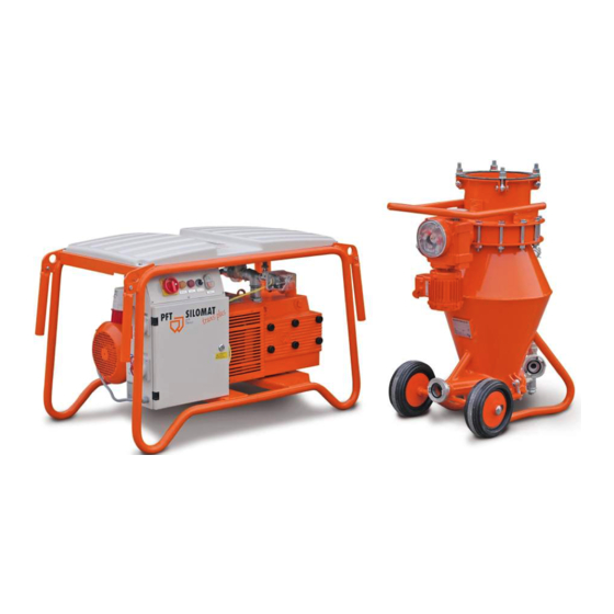
PFT SILOMAT trans plus 105 RAL2004
Part 2: Overview and operation
Item number of operating manual 00609921
Item number of the machine parts list PFT SILOMAT trans plus 105 RAL2004
-00124365
Read the operating manual before starting any work!
Page 1
Advertisement
Table of Contents

Related Manuals for Knauf PFT SILOMAT trans plus 105


Summary of Contents for Knauf PFT SILOMAT trans plus 105
- Page 1 PFT SILOMAT trans plus 105 RAL2004 Part 2: Overview and operation Item number of operating manual 00609921 Item number of the machine parts list PFT SILOMAT trans plus 105 RAL2004 -00124365 Read the operating manual before starting any work!
- Page 2 © Knauf PFT GmbH & Co. KG Einersheimer Straße 53 97346 Iphofen Germany Postfach 60 D-97343 Iphofen Germany Tel.: +49 9323 31-760 Fax: +49 9323 31-770 Tel.: +49 9323 31-1818 (technical assistance hotline) E-mail: info@pft.net Internet: www.pft.net Page 2...
-
Page 3: Table Of Contents
PFT SILOMAT trans plus 105 RAL2004 Part 2: Overview and operation Contents Contents 14.2 Safety systems air compressor ..15 14.3 General positioning of the air compressor ........16 Contents ............3 14.4 Hot surface of the air compressor ..16 EC Declaration of Conformity ..... - Page 4 PFT SILOMAT trans plus 105 RAL2004 Part 2: Overview and operation Contents Check that all previously 26.2 Disconnecting the conveying container ..........34 loosened screw connections are fixed correctly. 43 27 Cleaning ............34 Check that all previously 27.1 Cleaning the pressure conveying removed protective devices and covers system ..........
-
Page 5: Ec Declaration Of Conformity
PFT SILOMAT trans plus 105 RAL2004 Part 2: Overview and operation EC Declaration of Conformity 2 EC Declaration of Conformity Company: Knauf PFT GmbH & Co. KG Einersheimer Straße 53 97346 Iphofen Germany declares under our sole responsibility that the product:... -
Page 6: Examination
PFT SILOMAT trans plus 105 RAL2004 Part 2: Overview and operation Examination 3 Examination 3.1 Examination by machine operator Prior to each shift, the machine operator has to examine the effectiveness of the control and safety devices as well as the proper fitting of the protection devices. -
Page 7: General Information
PFT SILOMAT trans plus 105 RAL2004 Part 2: Overview and operation General information 4 General information 4.1 Information regarding the manual This manual gives important notes and instructions on the correct use of the equipment. The adherence to all defined safety and handling instructions is a prerequisite for a safe working environment. -
Page 8: Spare Part Lists
PFT SILOMAT trans plus 105 RAL2004 Part 2: Overview and operation Spare part lists 5 Spare part lists You can find spare part lists for the machine in the Internet under www.pft.net Accessories Page 8... -
Page 9: Technical Specifications
PFT SILOMAT trans plus 105 RAL2004 Part 2: Overview and operation Technical specifications 6 Technical specifications 6.1 General specifications SILOMAT trans plus 105 00124365 Total weight of the conveying Specification Value Unit system SILOMAT trans plus 105 275 kg Specification... -
Page 10: Operating Requirements
PFT SILOMAT trans plus 105 RAL2004 Part 2: Overview and operation Sound power level Motor protection switch Output Setting value Description Compressor 5,5 kW 11,2 A motor Drive 0.18 kW 0,65 A Fig. 1: Motor protection switch 6.3 Operating requirements... -
Page 11: Dimension Sheet: Pft Silomat Trans Plus
PFT SILOMAT trans plus 105 RAL2004 Part 2: Overview and operation Dimension sheet: PFT SILOMAT trans plus 9 Dimension sheet: PFT SILOMAT trans plus 1150 Abb. 2: Dimension sheet 10 Name plate The type plate is located at the right bottom of the hopper and... -
Page 12: Design And Function
PFT SILOMAT trans plus 105 RAL2004 Part 2: Overview and operation Design and function 12 Design and function 12.1 Overview of the assemblies Fig. 5: Overview of the assemblies 1. Silo / container 10. Material hose connection to cleaning machine 2. -
Page 13: Assembly Description
PFT SILOMAT trans plus 105 RAL2004 Part 2: Overview and operation Design and function 12.2 Assembly description Fig. 6: Description of switching box and operating elements Switching box: 1. Main reversing switch (also used as emergency stop switch. 2. Control lamp – direction of rotation changed. -
Page 14: Function
PFT SILOMAT trans plus 105 RAL2004 Part 2: Overview and operation Function 13 Function 13.1 Function description and operating sequence As soon as the level sensor of the cleaning machine reports “Empty”, the block flap opens (“Open” position) and the conveying container is filled with approx. 62 l of dry material with the silo butterfly valve open. -
Page 15: Intended Use Air Compressor
PFT SILOMAT trans plus 105 RAL2004 Part 2: Overview and operation Intended use air compressor 14 Intended use air compressor 14.1 Intended purpose air compressor The tool is conceptualised and designed exclusively for the purpose of use specified here. Attention! -
Page 16: General Positioning Of The Air Compressor
PFT SILOMAT trans plus 105 RAL2004 Part 2: Overview and operation Intended use air compressor 14.3 General positioning of the air compressor The air compressor complies with the national and international safety regulations and can therefore also be used in damp rooms and/or outdoors. -
Page 17: Transportation, Packaging And Storage
PFT SILOMAT trans plus 105 RAL2004 Part 2: Overview and operation Transportation, packaging and storage 15 Transportation, packaging and storage 15.1 Safety instructions for transportation Improper transport CAUTION! Damages can be caused by improper transport! Significant damages may arise when items are transported incorrectly. -
Page 18: Transportation
PFT SILOMAT trans plus 105 RAL2004 Part 2: Overview and operation Transportation, packaging and storage 15.2 Transportation Attachment points To transport using a crane, attach a belt to the Silomat system on the attachment eyelets (1). Attaching the system Strike hook according to the crane hook. -
Page 19: Transportation Checks
PFT SILOMAT trans plus 105 RAL2004 Part 2: Overview and operation Transportation, packaging and storage 15.3 Transportation checks Inspect the goods for damage and missing parts immediately on delivery. If external transportation damage can be seen, proceed as follows: Do not accept the delivery, or accept it only under reservations. -
Page 20: Safety
PFT SILOMAT trans plus 105 RAL2004 Part 2: Overview and operation Safety 16 Safety The following protective equipment has to be worn for all operative Personal protective equipment work: Protective clothing Protective goggles Protective gloves Safety shoes ... -
Page 21: Preparations
PFT SILOMAT trans plus 105 RAL2004 Part 2: Overview and operation Preparations 17 Preparations Before operating the machine, carry out the following preparations: WARNING! SILOMAT systems for free-fall silos may only be connected to depressurised silos / containers. The dust removal lines of the silo / container must be open and unclogged. -
Page 22: Preparing The Conveying Container
PFT SILOMAT trans plus 105 RAL2004 Part 2: Overview and operation Preparing the conveying container 19 Preparing the conveying container 19.1 Connecting the conveying container 1. Connect the conveying container (1) to the silo outlet flap (2). NOTE! Ensure that the silo / container flap is closed correctly so that no more material is conveyed. -
Page 23: Conveying Line
PFT SILOMAT trans plus 105 RAL2004 Part 2: Overview and operation Connectings 19.3 Conveying line NOTE! To ensure that the system works optimally over long conveying distances, the conveying line should not only be laid out flatly. We therefore recommend that you create inclinations. -
Page 24: Open The Silo Outlet Flap
PFT SILOMAT trans plus 105 RAL2004 Part 2: Overview and operation Open the silo outlet flap 3. Connect the control cable from the panel mounted socket (1) to the rotary wing sensor of the injection hood (3). Fig. 17:Connecting the control cable 4. -
Page 25: Switching On The Machine And Putting It Into Service
PFT SILOMAT trans plus 105 RAL2004 Part 2: Overview and operation Switching on the machine and putting it into service 22 Switching on the machine and putting it into service Switch on the main reversing switch. NOTE! Check the direction of rotation. Pay attention to the direction arrow on the motor. -
Page 26: Problematic Materials For Conveying
PFT SILOMAT trans plus 105 RAL2004 Part 2: Overview and operation Switching on the machine and putting it into service NOTE! A level sensor is found in the injection hood of the cleaning machine which signals the material requirements to the SILOMAT system over the control line. -
Page 27: Switching Off
PFT SILOMAT trans plus 105 RAL2004 Part 2: Overview and operation Switching off in an emergency 22.3 Switching off 1. Switch off the system by pressing the ON / OFF switch (1). 2. Turn the manual – 0 – automatic switch (2) to the “0” position. -
Page 28: Action On Power Failure
PFT SILOMAT trans plus 105 RAL2004 Part 2: Overview and operation Action on power failure Action on power failure 24.1 De-energising the system NOTE! The system is de-energised by turning the main reversing switch to the “0” position. Fig. 26: Switching off When working on the control box, the power supply must be interrupted by removing the connection cable. -
Page 29: Work On Troubleshooting
PFT SILOMAT trans plus 105 RAL2004 Part 2: Overview and operation Work on troubleshooting 25 Work on troubleshooting 25.1 Reaction in the event of faults Handling malfunctions The following points apply in case of malfunctions: 1. Carry out an emergency stop immediately for all malfunctions that can lead to material damage or personal injury. -
Page 30: Safety
PFT SILOMAT trans plus 105 RAL2004 Part 2: Overview and operation Work on troubleshooting 25.4 Safety Protective gear The following protective equipment has to be worn for all maintenance work: Protective clothing. Protective goggles, protective gloves, safety shoes, ear ... - Page 31 PFT SILOMAT trans plus 105 RAL2004 Part 2: Overview and operation Work on troubleshooting Conveying time or request is Check the parts and replace if required Service technician defective End switch on drive defective Replace or readjust the end switch...
-
Page 32: Dealing With Mlfunctions
PFT SILOMAT trans plus 105 RAL2004 Part 2: Overview and operation Work on troubleshooting 25.6 Dealing with mlfunctions 25.6.1 Clearing hose blockages Made by operator. Additional safety equipment: Face guard NOTE! Close the silo outlet flap (1). -
Page 33: End Of Work
PFT SILOMAT trans plus 105 RAL2004 Part 2: Overview and operation End of work 7. Turn the manual – “0” – automatic switch (4) to the “MANUAL” setting. Let the compressor run until the hoses are empty. 8. Switch back to automatic operation (4). -
Page 34: Disconnecting The Conveying Container
PFT SILOMAT trans plus 105 RAL2004 Part 2: Overview and operation Cleaning 26.2 Disconnecting the conveying container Loosen flange nuts (1) 2. Disconnect the conveying container (2) from the silo / container (3). Fig. 35: Disconnecting the conveying container 27 Cleaning 27.1 Cleaning the pressure conveying system... - Page 35 PFT SILOMAT trans plus 105 RAL2004 Part 2: Overview and operation Cleaning 4. Move the drive to the “CLOSED” position by turning the handwheel (3). Fig. 38: Actuator 5. Turn the manual – 0 – automatic switch (4) to the MANUAL position.
-
Page 36: Maintenance
PFT SILOMAT trans plus 105 RAL2004 Part 2: Overview and operation Maintenance 28 Maintenance 28.1 Safety Personnel Unless otherwise stated, the maintenance tasks detailed here can be carried out by the machine operator. Some maintenance tasks may only be carried out by specialist ... -
Page 37: Maintenance Plan
PFT SILOMAT trans plus 105 RAL2004 Part 2: Overview and operation Maintenance DANGER! Ensure that conveying system depressurised and de-energised when working with the SILOMAT trans plus. 1. Switch off the system by pressing the red OFF switch (1). 2. Turn the manual – “0” – automatic switch (2) to the “0”... -
Page 38: Lubricating The Bearings
PFT SILOMAT trans plus 105 RAL2004 Part 2: Overview and operation Maintenance tasks Interval Maintenance task To be made by Weekly Cleaning the filter cartridges Operator After 1000 hours of Lubricating the bearings Operator operation Yearly Checking the slider width Service technician 28.3 Lubricating the bearings... -
Page 39: Cleaning The Filter
PFT SILOMAT trans plus 105 RAL2004 Part 2: Overview and operation Cleaning the filter 30 Cleaning the filter 30.1 Unscrew the filter cover 1. Unscrew the filter cover (1). Fig. 46: Filter cover 2. Remove the filter cartridges C 1112/2 (2) and filter cartridge polyester. -
Page 40: Checking The Slider Width
PFT SILOMAT trans plus 105 RAL2004 Part 2: Overview and operation Cleaning the filter 30.2 Checking the slider width Made by the service technician. Check the slider width yearly: 1. The width of the sliders (1) must not fall below the defined minimum (26 mm). -
Page 41: When Working On And In The Control Box
PFT SILOMAT trans plus 105 RAL2004 Part 2: Overview and operation Cleaning the filter 30.4 When working on and in the control box Implementation by an electrician or a person trained in electrical engineering: 1. Turn the main reversing switch to the “0” position. - Page 42 PFT SILOMAT trans plus 105 RAL2004 Part 2: Overview and operation Cleaning the filter Air pressure safety switches The machine is switched on at 0.8 bar. Fig. 53: Air pressure safety switches NOTE! The pressure control is installed as standard. When the pressure control is attached, the conveying time is set to approx.
-
Page 43: Checking The Pressure Control
PFT SILOMAT trans plus 105 RAL2004 Part 2: Overview and operation Checking the pressure control Checking the pressure control Checking the pressure control 1. Kink the black pressure hose. 2. Let the set conveying time elapse. 3. Open the hose carefully. -
Page 44: Disassembly
PFT SILOMAT trans plus 105 RAL2004 Part 2: Overview and operation Disassembly 32 Disassembly The machine must be disassembled and disposed of correctly after reaching its end of use. 32.1 Safety Personnel Disassembly may only be made by specially trained personnel. -
Page 45: Electrical System
PFT SILOMAT trans plus 105 RAL2004 Part 2: Overview and operation Disassembly 32.2 Electrical system DANGER! Danger of death due to electric current! Contact with live components can lead to death or serious injury. Live electrical components can move uncontrollably and cause serious injury. -
Page 46: Index
PFT SILOMAT trans plus 105 RAL2004 Part 2: Overview and operation Index 33 Index Examination ............6 Accessories ............8 Examination by machine operator ....... 6 Action on power failure ........28 Assembly description ......... 13 Fault displays ............. 29 Faults ..............29 Brief description .......... - Page 47 PFT SILOMAT trans plus 105 RAL2004 Part 2: Overview and operation Index Output values ............. 10 Safety instructions for transportation ....17 Overview of the assemblies........ 12 Safety systems air compressor......15 Schutzausrüstung Packaging ............. 17, 19 Bedienung ............20 Periodic inspection ..........6 Solving malfunctions ...........32...
- Page 48 PFT SILOMAT trans plus 105 RAL2004 Part 2: Overview and operation PFT - ALWAYS AT YOUR SITE Knauf PFT GmbH & Co. KG Postfach 60 97343 Iphofen Einersheimer Straße 53 97346 Iphofen Germany Tel: +49 9323 31-760 Fax: +49 9323 31-770 Technical hotline: +49 9323 31-1818 info@pft.net...
Need help?
Do you have a question about the SILOMAT trans plus 105 and is the answer not in the manual?
Questions and answers