Table of Contents
Advertisement
Quick Links
Advertisement
Table of Contents

Related Manuals for Kohler VOLT VK4X1E


Summary of Contents for Kohler VOLT VK4X1E
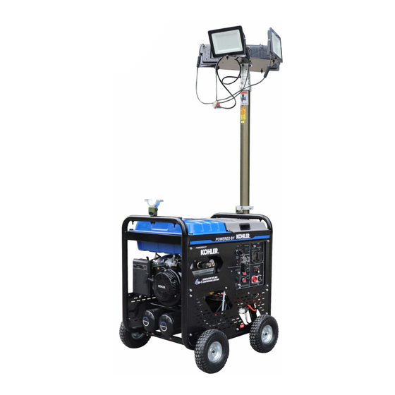
- Page 1 4 In 1 OPERATOR'S MANUAL MODEL-VK4X1E Owners Manual...
- Page 2 We want to thank you for your purchase of our state of the Multi-Functional 4 in 1 Machinery. This manual will tell you how to use and maintain. Please read the manual carefully before operating the machine. Operating the machine in the best conditions will increase the lifetime of the unit.
-
Page 3: Table Of Contents
Catalogue 1.Safety…………………………………………..1 2.Specifications…………………………………4 3.Component Identification…………………...5 4.Preparation……………………………….…..9 5.Starting……………………………………….12 6.Operation…………………………………..13 7.Engine Shut down…..………………….14 8.Maintenance…………………………………15 9.Common Faults and troubleshooting…..23 10. Schematic Diagram………………………26... -
Page 4: Safety
1.Safety Instruction Please read the manual before operation, failure to comply with the manual could lead to danger of operator, others and the machine. 1.1.Protect yourself and others. Welding can make you and others in danger of many risk factors: Make sure to never weld without a welding mask. - Page 5 protection. Do not let your body touch the ground and the electrode at that same time. 1.4 Welding fumes and gasses can cause serious harm to operator and all other by standards. Please keep your head away from a place you could possibly breathe in fumes and make sure to use the machine in a well ventilated area.
- Page 6 1.10. The engine operates on gasoline. It is important to keep in mind this unit cannot be run indoors. Carbon Monoxide has no odor and can be fatal in a short period of time. 1.11. Gasoline is highly flammable and is capable of causing a large explosion.
-
Page 7: Specifications
2.Specifications 50A-200A Welding AC120/240V, 60Hz Engine Working voltage(V) AC120V/240V ±5% LED/4×100W Lamp power(W) Lighting Solenoid valve 2pcs/DC12V/5W Lifting gear pressure(MPa) 0.8 ±0.1 Lift height(mm) 1800-4500 168KG... -
Page 8: Component Identification
Component Identification Note: Do not attempt to modify the control panel in any way. This will void your warranty and could present the potential for equipment failure and personal injury. . 7. Socket for welding Main Switch . . lighting control switch Air compressor switch .... - Page 9 1. Engine Cover Plate 2. Fuel Tank 3. Fuel Petcock 4. Engine Pull-Start Assembly 5. Engine Choke Lever 6. Air Filter Assembly 7. Handle 8. Water Drain Valve 9. Muffler Assembly 10. Frame 1. Air Compressor Oil Drain Plug 2. Oil Sight Glass 3.
- Page 10 1. Engine Oil Drain Plug 2. Oil Fill Dipstick 3. Air Pressure Relay 4. A/C Switch 5. Safety Valve 1. Pressure Gauge 2. Air Pressure Regulator 3. Air Outlet Connectors 4. Pressure Gauge 5. Air Tank 6. Air Hose 7. Air Valve 8.
- Page 11 Lighting fixing device Lighting shift device Lift and drop arod assy Lamps assy Air outlet Lighting lock device Lighting fixing device...
-
Page 12: Preparation
4、Preparation 4.1 Read this manual carefully and understand all operating procedures before using the equipment. 4.2 Make sure the wheel kit is firmly mounted before any type of movement. Please control the speed to avoid jerking. 4.3 The equipment must be stored horizontally in a clean, dry, well ventilated place. - Page 13 Always check the API SERVICE label on the oil container to be sure it includes the letters SE. 4.6.2 Check and change the oil in your machine regularly. This will avoid all problems related to the oil being too low, too high, dirty or thick.
- Page 14 foam filtering air filter cover Button core Air filter element 4.7 Always check the fuel level before operating machinery. Use a strainer when adding fuel and make sure to always leave enough room at the top for fuel inflation to occur. Make sure you securely twist the fuel cap before operating.
-
Page 15: Starting
lighting was fixed well compressor 4.9.2 After the operation meet the starting air start the air compressor. After the air pressure more than 0.3Mpa,open the lift and drop switch, the lamp arrive the suitable height,then open the lighting switch on the control panel. 5.Starting Fuel switch 5.1 Start the fuel valve... -
Page 16: Operation
5.2.2 Recoil start: Make sure the unit to the unit is in the “on” position. Pull the re-cooil handle slightly until you feel resistance and then pull handle immediately. If failed, repeat until the unit has started. Gentle let the cord back down to avoid damaging the pull cord. -
Page 17: Engine Shut Down
true pleased check the other equipment is running properly. Second check if it is overloaded. Special Warning 1. The CB is not in control of the power of the welder. 2. Do not use the welder and air compressor at the same time or generator and welder at the same time for best performance. -
Page 18: Maintenance
empty compressor tank of all remaining air. If welding please remove rod connections. Let the unit run for 2-3 minutes, then turn the key on the control panel to the “off” position. 7.2 If the unit must be transported a long distance. Make sure you stop the unit and remove any connections. - Page 19 Change oil(when warm the unit, remove the oil to make sure that the drain the oil completely) Daily maintance cycle the first every every Item: based on the runing target every 1year each time each time month or month or 3month or 3month or 6month or...
- Page 20 CAUTION: In order to protect the environment we strongly urge all users to drain the oil into a sealed container. Once finished please dispose of the oil into an oil waste barrel or to a local company that handles waste oil. 8.2 Cleaning the air filter 8.2.1 Use warm soapy water when cleaning the air filter.
- Page 21 spark plug wrench Side electrode Sealing ring spark plug cap CAUTION: If the spark plug is not fully tightened when reinstalling it could cause the engine to overheat. It is important to avoid any damage that the spark plug is tightened to the correct specifications.
- Page 22 on the spark plug. 8.3.1 After letting the unit cool down clean a dirty spark plug by first, removing the cap on the plug. Then you must remove the spark plug with the spark plug remover tool that came in the toolbox of your unit.
- Page 23 Attention: come into eye carelessly: use water in the container to wash at least 15 minutes. (water with pressure will let eye injured), then have medical treatment; Contact with skin carelessly: take off cloth and wash skin with much water, then have medical treatment; Come into body carelessly: drink a lot of water or milk, then have medical treatment.
- Page 24 8.6.1 Put a gasoline container below the carburetor and use a funnel to protect against over spilling. 8.6.2 Loosen carburetor discharge bolt. Discharge any remaining fuel in the carburetor. 8.6.3 After discharging of all fuel into a container re tighten the discharge bolt.
- Page 25 ATTENTION: When using the machine and you hear unfamiliar stop the machine, noises coming from the unit, it is important to and call your local dealer immediately. 8.7 Compressor maintenance 8.7.1 For any air compressor oil changes please refer to the engine oil change.
-
Page 26: Common Faults And Troubleshooting
9.Common fault and processing methods fault fault cause failure process phenomenon charge battery( only for electric 1. battery low voltage start) Open fuel cock 2. fuel cock not open Refer step 3 3. Chock valve not open Check oil level, add to the level 4. - Page 27 Working pressure high reduce working pressure Not use correct lubricating oil reference this manual and use compressor Ambient high temperature or poor correct compressor oil part ventilation Shift to good ventilation place overheat compressor valve block air repair valve block or replace temperature leakage or damage compressor...
- Page 28 1.the Solenoid valve damaged 1.change solenoid valve 2.check the wires and reconnect 2.short circuit The lighting 3.the air pressure was not enough 3.Adding the air pressure and make can't rise and drop it more than 0.3Mpa 4.the drop and rise switch on the contrl panel damaged 4.Change 5.air leakage...
-
Page 29: Schematic Diagram
10.Schematic diagram... - Page 30 Notes Volt Email: INFO@VOLT-EQUIPMENT.COM TEL: 1-888-207-VOLT MAILING: 128 MILPORT CIRCLE SUITE 101 GREENVILLE SC 29607...
Need help?
Do you have a question about the VOLT VK4X1E and is the answer not in the manual?
Questions and answers