
Subscribe to Our Youtube Channel
Related Manuals for THOMSON DTH175EL


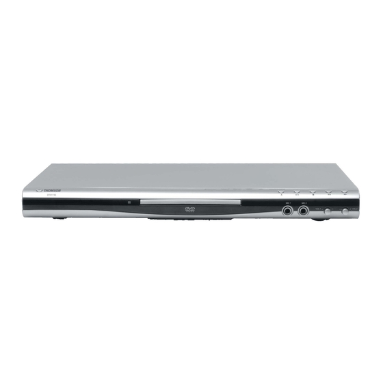
Summary of Contents for THOMSON DTH175EL
- Page 1 All manuals and user guides at all-guides.com THOMSON DTH175EL Service Manual THOMSON DTH175EL Service Manual...
-
Page 2: Table Of Contents
All manuals and user guides at all-guides.com THOMSON DTH175EL Service Manual Table of Contents General Section Cautions/Warnings Safe Warnings Precautions Software Upgrade Exploded View Circuit Diagram and Component Layout MPEG IC Block Diagrams Power supply Circuit Diagram and Component Layout... -
Page 3: General Section
All manuals and user guides at all-guides.com THOMSON DTH175EL Service Manual General Section Cautions/Warnings Product Safety Notice Parts marked with the symbol in the schematic diagram have critical characteristics. Use ONLY replacement pares recommended by the manufacturer. It is recommended that the unit be operated from a suitable DC supply or batteries during initial check out procedures. -
Page 4: Safe Warnings
All manuals and user guides at all-guides.com THOMSON DTH175EL Service Manual Safe Warnings Protection of Eyes from Laser Beam To protect eyes from invisible laser beam during servicing DO NOT LOOK AT THE LASER BEAM Laser Caution CAUTION Adjusting the knobs, switches, and controls, etc. or taking actions not specified herein may result in a harmful emission of laser beams. -
Page 5: Precautions
All manuals and user guides at all-guides.com THOMSON DTH175EL Service Manual Precautions ESD Precautions in Repairing 1. Do not apply excessive pressure on the mechanical parts (moving pares), including the Pickup Block, as extremely high mechanical precision or required in these parts. -
Page 6: Software Upgrade
All manuals and user guides at all-guides.com THOMSON DTH175EL Service Manual Software Upgrade You can upgrade DVD Player using the software we provide as following step: ― Creating a software upgrade CD ― Use only a new CD-R/CD-RW(not an erased one). -
Page 7: Exploded View
All manuals and user guides at all-guides.com THOMSON DTH175EL Service Manual Exploded View... -
Page 8: Circuit Diagram And Component Layout
All manuals and user guides at all-guides.com THOMSON DTH175EL Service Manual Circuit Diagram and Component Layout MPEG IC Block Diagrams Fig. 2-1 MT1389... - Page 9 All manuals and user guides at all-guides.com THOMSON DTH175EL Service Manual Fig. 2-2 Functional block diagram Fig.2-3 DVD Player system Diagram...
- Page 10 All manuals and user guides at all-guides.com THOMSON DTH175EL Service Manual Table1. 1389C Pin Description...
- Page 11 All manuals and user guides at all-guides.com THOMSON DTH175EL Service Manual Table1. 1389C Pin Description (continued)
- Page 12 All manuals and user guides at all-guides.com THOMSON DTH175EL Service Manual Table1. 1389C Pin Description (continued)
- Page 13 All manuals and user guides at all-guides.com THOMSON DTH175EL Service Manual Table1. 1389C Pin Description (continued)
- Page 14 All manuals and user guides at all-guides.com THOMSON DTH175EL Service Manual Table1. 1389C Pin Description (continued)
- Page 15 All manuals and user guides at all-guides.com THOMSON DTH175EL Service Manual Table1. 1389C Pin Description (continued)
- Page 16 All manuals and user guides at all-guides.com THOMSON DTH175EL Service Manual Table1. 1389C Pin Description (continued)
- Page 17 All manuals and user guides at all-guides.com THOMSON DTH175EL Service Manual Table1. 1389C Pin Description (continued)
- Page 18 All manuals and user guides at all-guides.com THOMSON DTH175EL Service Manual Table1. 1389C Pin Description (continued)
- Page 19 All manuals and user guides at all-guides.com THOMSON DTH175EL Service Manual Table1. 1389C Pin Description (continued)
- Page 20 All manuals and user guides at all-guides.com THOMSON DTH175EL Service Manual Table1. 1389C Pin Description (continued)
- Page 21 All manuals and user guides at all-guides.com THOMSON DTH175EL Service Manual Table1. 1389C Pin Description (continued)
- Page 22 All manuals and user guides at all-guides.com THOMSON DTH175EL Service Manual Table1. 1389C Pin Description (continued)
-
Page 23: Power Supply Circuit Diagram And Component Layout
All manuals and user guides at all-guides.com THOMSON DTH175EL Service Manual Power supply Circuit Diagram and Component Layout Fig 2-4 Power Supply Circuit Diagram Fig 2-5 Power Supply Assembly Drawing... - Page 24 All manuals and user guides at all-guides.com THOMSON DTH175EL Service Manual Fig 2-6 Power Supply Composite...
-
Page 25: Mpeg Circuit Diagram And Component Layout
All manuals and user guides at all-guides.com THOMSON DTH175EL Service Manual MPEG Circuit Diagram and Component Layout MPEG Circuit Diagram Fig 2-7 Index and Power Interface... - Page 26 All manuals and user guides at all-guides.com THOMSON DTH175ELService Manual Fig2-8 MTK1389 MPEG & RF Fig 2-9 SDRAM & FLASH...
- Page 27 All manuals and user guides at all-guides.com THOMSON DTH175EL Service Manual Fig 2-10 Video output Fig 2-11 Audio output...
- Page 28 All manuals and user guides at all-guides.com THOMSON DTH175EL Service Manual MPEG Assembly Drawing Fig 2-12 MPEG Assembly Drawing MPEG Composite...
- Page 29 All manuals and user guides at all-guides.com THOMSON DTH175EL Service Manual Fig2-13 MPEG Composite...
-
Page 30: Front Panel Circuit Diagram And Component Layout
All manuals and user guides at all-guides.com THOMSON DTH175EL Service Manual Front panel Circuit Diagram and Component Layout Fig 2-14 Front Panel Circuit Diagram Fig 2-15 Front Panel Assembly Drawing... - Page 31 All manuals and user guides at all-guides.com THOMSON DTH175EL Service Manual Fig 2-16 Front Panel Composite...
-
Page 32: Servicing Procedures
All manuals and user guides at all-guides.com THOMSON DTH175EL Service Manual Servicing Procedures Power Supply Trouble Service Flow Chart Power Supply Block Trouble Check F901 Condition Replace F901 Check U901 Pin1/Pin2 Replace U901 Condition Check on D101/D102/ D103/D104/D105 Output Voltage Condition... -
Page 33: Read Disc Trouble Service Flow Chart
All manuals and user guides at all-guides.com THOMSON DTH175EL Service Manual Read Disc Trouble Service Flow Chart Read disc problem in a DVD player is a very complicated issue that may involve complex issues. This problem is not only relation to the electronic circuit, but also very much relation to the operation environment. -
Page 34: Composite Video Trouble Service Flow Chart
All manuals and user guides at all-guides.com THOMSON DTH175EL Service Manual Composite Video Trouble Service Flow Chart Composite Video Trouble Check “SETUP” Item See “User Manual” Check Y1 Output Signal Replace Y1 Parts Check C55/C56 Signal Replace C55/C56 Check D12/D14 Signal... -
Page 35: Scart Video Trouble Service Flow Chart
All manuals and user guides at all-guides.com THOMSON DTH175EL Service Manual SCART Video Trouble Service Flow Chart Composite SCART Video Trouble Check “SETUP” Item See “User Manual” Check Y1 Output Signal Replace Y1 Parts Check C49/C50/C53/ Replace C49/C50/C53/ C54/C57/C58 Signal... -
Page 36: S-Video Trouble Service Flow Chart
All manuals and user guides at all-guides.com THOMSON DTH175EL Service Manual S- Video Trouble Service Flow Chart Composite S- Video Trouble Check “SETUP” Item See “User Manual” Check Y1 Output Signal Replace Y1 Parts Check C47/C48/C51/ Replace C47/C48/C51/ C52 Signal... -
Page 37: Composite Analogy Audio Trouble Service Flow Chart
All manuals and user guides at all-guides.com THOMSON DTH175EL Service Manual Composite Analogy Audio Trouble Service Flow Chart Composite Analogy Audio Trouble Check R138 Signal Replace U4 Check U14 Pin2~4 Signal Replace U4 Check U14 Pin28 +5V Check Power Supply... -
Page 38: Front Control Trouble Service Flow Chart
All manuals and user guides at all-guides.com THOMSON DTH175EL Service Manual Front Control Trouble Service Flow Chart Front Control Trouble Check between JP2 and Power Connection Replace Check between JP1 and MPEG Connection Check U2 Pin9/25 Voltage See: 3.1 Check U2... -
Page 39: Remote Control Trouble Service Flow Chart
All manuals and user guides at all-guides.com THOMSON DTH175EL Service Manual Remote Control Trouble Service Flow Chart Remote Control Trouble Check Remote Control Replace Battery Replace Control Check U3 Pin2 Voltage Check Power Supply Check U3 Pin3 Output Signal Replace U3... -
Page 40: Parts List
All manuals and user guides at all-guides.com THOMSON DTH175EL Service Manual Parts List Power parts list PART NO. DESCRIPTION LOCATION Carbon Resistor 1 M2R1110030433110 RT14-1/4W-10R±5% R122,R902 2 M2R1110230433110 RT14-1/4W-1K±5% R111,R101,R110,R112,R121, M2R1120230433110 RT14-1/4W-2K±5% R109 3 M2R1110430433110 RT14-1/4W-100K±5% R903 4 M2R1110530233110 RT15-1/2W-1M±5%... - Page 41 All manuals and user guides at all-guides.com THOMSON DTH175EL Service Manual PART NO. DESCRIPTION LOCATION 24 M2D10FR104220000 FR104 ( DO-41 ) D101,,D103,D907 25 M2D1IN5392220000 1N5392- ( DO-41 ) D108,D109 26 M2D1IN5822220000 IN5822 D105 Certain VOLT Diode 27 M2D1BZX12V220000 BZX-12V-1/2W- ( DO-35 )...
- Page 42 All manuals and user guides at all-guides.com THOMSON DTH175EL Service Manual MEPG Parts List PART NO. DESCRIPTION LOCATION Chip Resistor 1 M2R0000030811000 RC-05K000OT 2 L3,L10 2 M2R001R030811000 RC-05K1R0JT 4 R42~R45 3 M2R0033030811000 RC-05K330JT 1 R82 4 M2R0000031000000 RC-03K000OT 24 R11,R20,R21,R26~R31,R40,R79,R80,...
- Page 43 All manuals and user guides at all-guides.com THOMSON DTH175EL Service Manual PART NO. DESCRIPTION LOCATION 28 M2R0015331000000 RC-03K153JT 2 R14,R49 29 M2R0018331000000 RC-03K183JT 1 R47 30 M2R0020331000000 RC-03K203JT 4 R46,R51,R53,R56 31 M2R0022331000000 RC-03K223JT 6 R110,R123,R132,R146,R152,R158 32 M2R0010431000000 RC-03K104JT 18 R7,R16,R32,R35,R111,R125,R119...
- Page 44 All manuals and user guides at all-guides.com THOMSON DTH175EL Service Manual PART NO. DESCRIPTION LOCATION C43,C46,CB83,CB68,CB71,CB85 CB84,CB64,CB66,CB69 CB72~CB76 57 M2C0474B84080500 CC-0805F474Z160NT 1 C19 58 M2C0105B84060300 CC-0603F105Z160NT 6 C15,C16,C23~C26 ELECT Capacitor 59 M2C2106B57051122 CD11-16V-10U-M 11 CE40,CE44,CE46,CE48,CE49,CE51 CE53,CE1,CE15,CE24,CE55 60 M2C2476B89051122 CD11-16V-47U-M 11 CE7,CE16~CE18,CE21~CE23,CE27...
- Page 45 All manuals and user guides at all-guides.com THOMSON DTH175EL Service Manual PART NO. DESCRIPTION LOCATION Jack 1 HA1 79 M2P88FPC24005000 JP24-05M 80 M2P000000PH5A000 PH-5A 1 J4 1 J1 81 M2P000000PH6A000 PH-6A 1 J2 82 M2P00000PH6AB000 PH-6A-B 1 CON1 83 M2P0000TJC35A000 TJC3-5A 84 M2P11AV684120003 AV6-8.4-12-03...
- Page 46 All manuals and user guides at all-guides.com THOMSON DTH175EL Service Manual PART NO. DESCRIPTION LOCATION M2I0M29W80070000 M29W800DT-TSOP48 1 U11 M2I029W800B70000 M29W800DB-TSOP48 1 U11 M2IMX29LV800AT00 MX29LV800ATTI - 70 - TSOP 1 U11 M2IAT49LV8192000 AT49LV8192AT-70TC 1 U11 M2IAT49F8192AT00 AT49F8192AT-70TC 1 U11 101 M2IAZ4558AM00000 AZ4558AM-SSOP8...
-
Page 47: Front Panel Parts List
All manuals and user guides at all-guides.com THOMSON DTH175EL Service Manual Front panel parts list PART NO. DESCRIPTION LOCATION Carbon Resistor 1 M2R1147130633110 RT13-1/6W-470R±5% 2 M2R1110330633110 RT13-1/6W-10K±5% R1 R4 R5 R6 R9 R10 3 M2R1151330633110 RT13-1/6W-51K±5% Porcelain Capacitor 4 M2C1101F44000022... -
Page 48: Av Output Parts List
All manuals and user guides at all-guides.com THOMSON DTH175EL Service Manual AV Output parts list PART NO. DESCRIPTION QTY LOCATION Chip Resistor 1 M2R0000030811000 RC-05K000OT Socket 2 M2P000000PH7A000 PH-7A 3 M2P11AV684120004 AV6-8.4-12-04 4 M2B100HY5996CH11 HY599-6CH Ver1.1 PCB (one side) SCART PART NO.
Need help?
Do you have a question about the DTH175EL and is the answer not in the manual?
Questions and answers