
Related Manuals for DMQ QC5 Series


Summary of Contents for DMQ QC5 Series
- Page 2 P/N: QC5 501 – ENG – Rev. 01 – February 2014...
- Page 3 Chapter 1 First steps Know the QC5 1.1.1 Front panel 1.1.2 Connectors Install and replace batteries Connecting the probe The “Q” key Display illumination and contrast 1.5.1 Display backlight illumination 1.5.2 Display contrast Locking and unlocking the keypad Chapter 2 Measuring with the QC5 Numerical measuring screen Graphical measuring screen (Histogram)
- Page 4 3.2.2 Alarm settings 3.2.3 Select language 3.2.4 Unit information General configuration options 3.3.1 Set time and date 3.3.2 Set time and date format 3.3.3 Set keypad sensitivity 3.3.4 Set auto-off time 3.3.5 Adjust display contrast 3.3.6 Beep activation 3.3.7 Introduction screen 3.3.8 Owner information 3.3.9...
-
Page 5: Additional Information
Actions over single files 4.4.1 View data in a single file 4.4.2 The “Q” key in a grid 4.4.3 The “Q” key in a histogram 4.4.4 Send data from a single file 4.4.5 Rename a file 4.4.6 View file size Actions over all files 4.5.1 Send all files... - Page 6 And thank you for purchasing a QC5 coating thickness gauge. At dmq we develop, manufacture and distribute software and quality control instruments offering innovation and solutions that come as a direct result of listening to your needs as a user. We apply some of the latest technology available in the industry to build instruments that are robust, precise, and easy to operate.
- Page 7 The information included in this manual applies to all QC5 series coating thickness gauges including models F, DLF, N, DLN, C and DLC. dmq is a registered trademark of Demeq S.R.L and its affiliate companies. The information contained in this manual is intended to educate users on the operation of the QC5 coating thickness gauges.
- Page 8 When a low frequency magnetic field is applied on a ferrous substrate, the signal induced by the coil inside the probe is proportional to the distance between the probe and the base. Figure 1: Ferrous base measuring principle Induced currents are produced on the metal surface when a high frequency field is applied.
- Page 9 D1400, ASTM B244 for models QC5 N & QC5 C; and ASTM D7091, ASTM E376 for all QC5 models. All QC5 series coating thickness gauges are for industrial use only. The QC5 operates on two AA size batteries. We strongly recommend that you use only top brand name alkaline batteries.
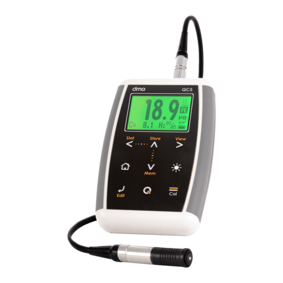
- Page 10 Figure 1.1: Front of the unit Graphic LCD display with LED backlight illumination Move Left key / View partial statistics (Stat) Move Up key / Manually store a value (Store) Move Right key / Switch to graphical measure mode screen (Graph) Menu key / Enter and exit measure screen / Exit and return to menus (Home)
- Page 11 Move Down key / Quick access to memory menu screen options (Mem) Change backlight illumination key (On, Off, Auto) Enter key / Edit values on the measure screen (Edit) key: Power On and Shutdown (touch and hold for 2 seconds) / Make quick and short touches to activate special features 10.
- Page 12 The QC5 is powered by 2 (two) AA batteries that are placed in the battery compartment located in the back of the unit. To gain access to the battery compartment slide the cover as shown in figure 1.3-1 and gently push the extraction ribbon upward and slightly towards the right to release the batteries (figure 1.3-2).
- Page 13 Figure 1.4: Replace / Insert batteries Notes Always use new alkaline top brand batteries for extended battery life. Do not mix new and old batteries. Always replace both batteries. Rechargeable batteries type NiMH can be used but will result in less time of continuous operation. Chapter 1...
- Page 14 “Additional information, Error Messages”) The QC5 uses a type Lemo 0B 4-pin connector located on top of the unit. All dmq probes are provided with Cal-Tag technology allowing you to easily switch or replace probes. To connect the probe simply align the...
- Page 15 has three functions: When the unit is off, touch for 2 seconds to power on the unit. When the unit is on, touch for 2 seconds to shutdown the unit. With the unit on, making short touches to the will activate special functions described in each chapter of this manual.
- Page 16 The display contrast on all dmq units is digital. Touch the white dot located in the center of the vertical scrolling bar between the keys and a contrast window will open. Move your finger towards the top and or bottom of the dotted line to adjust the contrast on your display.
- Page 17 Sliding the finger to the left will unlock the keypad. Figure 1.9: Unlocking the keypad Important The keypad can only be locked and unlocked in the measuring screens. Chapter 1...
- Page 18 The QC5 can display measurements in 3 distinct modes where each mode shows specific information. To switch modes touch the key. Touch the key to change the complimentary information displayed on the screen (mode-1 and mode-2). Figure 2.1: Numerical measuring screens Name of the open folder where data is being stored (Page Average of the measurements within the group (N values) Datalogger mode indicator: X: Off - M: Manual –...
- Page 19 Blocked keypad icon indicator (Page 7) Probe measuring icon (probe on sample) 10. Type of base icon: FE, NF, A (Page 14) 11. User selected unit 12. Number of (N) values counter / indicator for real time group statistics 13. Position of the last stored value (Column, Row) 14.
- Page 20 Maximum thickness value within the group Minimum thickness value within the group Average within the group Active calibration mode (Page 15) Actual coating thickness measurement Battery level indicator Type of base icon: FE, NF, A (Page 14) Probe measuring icon (probe on sample) High alarm indicator (Page 26) 10.
- Page 21 Number of (N) values counter / indicator for real time group statistics Average within the group Actual coating thickness measurement Probe measuring icon (probe on sample) Type of base icon: FE, NF, A User selected unit Active calibration mode Battery level indicator Keys in all measuring screens have the following functions: : Touch to generate real time statistics based on the number of (N) stored values at the time this function is activated.
- Page 22 : Touch to exit the measure screen and enter the main menu. : Touch to view quick memory access options. : Enter calibration mode (page 15). : Touch to access the select / edit mode. 2 flashing arrows will appear over editable fields: base and unit. Figure 2.5: Select / edit mode ...
- Page 23 : Changes the backlight illumination. : Set display contrast. : Lock and unlock keypad. The QC5 model that you have determines what type of base you can measure: ferrous, non-ferrous, or both. On combined models where you can measure both types of bases, the base selection can be done manually, or automatically where the unit determines the type of base.
- Page 24 The QC5 offers 9 modes of calibration that are explained in detail in this section of the user manual. The following table summarizes all 7 calibration modes: Abbreviation Name Base Samples Offset Base & 1-Pt 1 a 9 ...
- Page 25 If the calibration mode you selected requires base calibration (measuring an uncoated base), this is the first screen that will appear on the unit: Figure 2.7: Base calibration screen Indicates the type of base as well as its uniformity (page 17) “Probe action”...
- Page 26 The graphic representation of the type of base, is also indicative of the base condition. When dirt, corrosion and or other surface irregularities are present on the base material, the graphic will turn less uniform. Sharper “teeth” mean less uniformity of the base material. Figure 2.9: Base material condition indicator On figure 2.8, “...
- Page 27 After the base calibration procedure is concluded, the unit will ask you to measure using a shim of a known thickness. For the calibration modes that do not require base calibration (1 point, 2 point and Swedish), the calibration process begins here. Follow the on-screen instructions and measure the shim of a known thickness value over the base.
- Page 28 For the methods above, the unit will activate the thickness measurement editor only when the required number of samples have been taken. Use the arrow keys to adjust the thickness to the nominal shim value and touch save. Figure 2.12: Shim calibration thickness adjustment screen With short touches on the key, preset calibration shim values can be loaded.
- Page 29 Note The order in which you use the shims (Shim 1 and Shim 2) based on their thickness is irrelevant. Tips Better results with these calibration methods are obtained using shims with lower and higher thickness values than the actual lowest and highest measurements that you will be taking.
- Page 30 To exit the calibration memory menu touch Important In order to obtain better results with your QC5, calibrate using a the test piece that you are actually going to measure or use a test piece sample that is in the same condition.
- Page 31 The QC5 allows you to increase or decrease a value (offset) to adjust for errors produced by surface irregularities. Correction values depend on the surface profile as described in the ISO 19840 standard and in the following table: Surface profile according Correction in µm to ISO 8503-1 Fine...
- Page 32 The instructions explained in this chapter apply to all of the menus in the unit. To scroll QC5 menu options use the cursor keys. When you reach the end of the menu and move to the next menu option it becomes circular as shown herein.
- Page 33 The text editor is used to input, modify and delete; letters, numbers and symbols. Figure 3.3: Alphanumeric editor screens Selected key Cursor Text to be edited Virtual keyboard Use the cursor keys on the unit to scroll the virtual keyboard until you find the character that you want to use and touch to select.
- Page 34 Move cursor to the left Move cursor to the right Delete character on which cursor is on Enter and exit Figure 3.5: Quick access keys for the virtual keyboard editor Touch the key to open the direct access keyboard to the most commonly used virtual keyboard keys.
- Page 35 To close the virtual keyboard touch Chapter 3...
- Page 36 The main menu is the first list of options you will see when you exit the measuring screen and it includes the most important unit settings. Touch from the measuring screen to access this menu. Figure 3.6: Main menu Note: Memory, Cfg. General, and Cfg. Measure options are explained later on in this manual in chapter 4, and in sections 3.3 and 3.4 of this same chapter.
- Page 37 on Alarms to open the alarm menu options. Touch Touch on High or Low to open the numbers editor where you can set alarm values using the cursor keys. Touch to save the alarm value that you entered and to return to the previous menu. Figure 3.8: Alarm menu options Alarm types that you can choose include: Beep: Audible intermittent alarm type.
- Page 38 Select Unit Info to view information including owner data as well as the software version that your unit is running. Figure 3.10: Unit information screens To switch between unit information screens touch the keys. To return to the main menu touch Note The information required to obtain model upgrade licenses is included in this option.
- Page 39 Touch on the Cfg. Configure option to open the general configuration options menu. Use the keys to scroll the menu. Touch to select any of the menu options. Touch to exit and to return to the previous menu. Figure 3.10: General configuration options menu Choose Set Clock to open the time editor and use the cursor keys to set the time.
- Page 40 Choose Clock Format to open the menu that allows you to set the time format (12Hs or 24Hs) and the date format (D/M/Y – M/D/Y). Touch on the option you wish to select and touch to save and exit. Figure 3.12: Date and time format menu options This option allows you to set the keypad sensitivity.
- Page 41 its previous setting. Chapter 3...
- Page 42 The factory default setting is 50. Under special conditions we suggest that the sensitivity level be changed. Tips If the unit will operated using security gloves we recommend that the sensitivity level be raised. To make the keypad “harder” simply lower the sensitivity level.
- Page 43 Contrast settings allow you to turn your screen lighter or darker where 1 is the lightest and 32 is the darkest. Touch on Contrast and use keys to change the contrast on your screen. Touch to save or touch to exit without making changes. Figure 3.15: Screen contrast settings Tips Contrast on LCD screens can change with temperature.
- Page 44 This option allows you to enter owner information (the info that would appear on the introduction screen). Touch on Set ID, enter the password (the factory default password is 12345) and touch to access user info menu options. Figure 3.16: Enter password to access the user info menu The user information that can be changed includes the following: Name: Set or change the owner name.
- Page 45 Important The factory default password is 12345. You can change this password after adding your user information. Certain configuration options on your QC5 unit can be locked in order to avoid unwanted changes. Use of the locking options allow a supervisor to optimize unit configuration settings required for a specific test and then pass the unit on to an operator for him or her to conduct the actual measurements knowing that the unit has been...
- Page 46 Configure: Lock or unlock configuration options such as calibration mode and type of base selection. Datalogger: Lock or unlock Datalogger configuration options. QC5 models can be changed with software licenses that you can purchase from Demeq. If you want to purchase an upgrade license we will need to know the following information: ...
- Page 47 After you enter the new license number the unit will respond with one of the following messages: Figure 3.20: Response messages after a license is entered If the license number that you entered is correct the unit will show an updated license screen where the newly purchased license appears followed by a checkmark.
- Page 48 Select Cfg. Measure from the main menu to display measuring configuration options. Correctly setting these options is critical in obtaining reliable measurements. Figure 3.22: Measuring configuration options menu Touch on Base to select the type of base you will be measuring Use the keys to scroll all menu options and touch...
- Page 49 Touch on Calibr. Mode to view all calibration modes. For more details on each calibration mode, refer to section 2.6 on page 15 of this manual. Use the keys to scroll all menu options and touch to select. To exit without making changes touch Figure 3.24: Calibration mode menu Touch to adjust the offset value by adding or deducting from the...
- Page 50 Touch on Samples to set the maximum number of samples that the unit will accept when calibrating. In ISO, SSPC-PA2, Swedish and Australian calibration modes the number of samples is preset but can also be edited. In other calibration modes, the number of samples cannot be modified.
- Page 51 Touch on Measure Mode to open the measure modes options menu. Use the keys to scroll all menu options and touch to select and enable. To disable touch again. To exit without making changes touch Figure 3.28: Measure mode options menu When Continuous is enabled, the unit will measure at a rate of up to 99 readings per minute and will continue to measure for as long as the probe is not lifted.
- Page 52 Here you can set high and low values that will be represented on the vertical axis of the histogram. Figure 3.30: Set histogram range Touch on Histo Range to open the histogram menu. Touch on High or Low to open the numbers editor where you can set values using the cursor keys.
- Page 53 on Activate to enable the number of layers in an absolute Touch value, or select Percentage to display as a percentage of the total coating thickness. Figure 3.32: Activated count layer mode The count layer mode is not represented in graphic modes. To set the known layer thickness, go to the Edit Counter option in the counter configuration menu and touch Use the...
- Page 54 Touch on Measure to open the measure modes options menu. Figure 3.34: Measure mode options menu and set nominal value The modes in which measurements are represented are: Absolute: The unit displays the real measured value. Differential: The value displayed is a result of the value obtained from calculating: Differential = Real value –...
- Page 55 In order to optimize the use of the Datalogger in all QC5 “DL” models, it is important that you understand how data is organized. In the QC5 data is stored in 8 individual files with alphanumeric names. Each file contains a grid with columns and rows. And each grid contains columns (identified with consecutive letters;...
- Page 56 Select Memory from the main menu to view all menu options for the Datalogger. This chapter explains how to create, organize, and view files. Figure 4.2: Memory menu Touch on Files and use the cursor keys to navigate the list of files in the unit.
- Page 57 Remember that only one file can be open at any given time so whenever a new file is created, if a file was already open, the file that was open will be closed. Once a file has been closed, it cannot be reopened and new values can no longer be stored.
- Page 58 Touch on View Data to view the contents of the file. Touch to exit the file. Figure 4.6: File view in grid format To move inside the grid use the cursor keys. Touch on a value to open a histogram that includes that same value as well as the values included in the foregoing cells within that column.
- Page 59 Touch to open the quick access menu that allows you to go directly to a position inside the grid. Select the Row, Column, and Cell using the keys. Figure 4.8: Quick access menu options in a grid Row: Enter a row number using the cursor keys so that when you touch the grid will position itself directly on that row.
- Page 60 Touch in the histogram to open the quick access menu that allows you to obtain statistical information on the group of values being displayed. Figure 4.9: Quick access menu options in a histogram Error: Displays the number of errors and error percentage values in the batch based on the high and low alarm settings.
- Page 61 Touch on Rename to open the text editor that allows you to change the file name. Touch on Size to view the number of stored values within a single file (and the size of the file as a percentage of total unit memory).
- Page 62 Touch to cancel and return to the previous menu or touch to begin deleting all files. Figure 4.11: Erase all confirmation screen When the erase all action has been confirmed the following screens will be displayed: Figure 4.12: Erase all progress screen Touch on the measuring screen to open the quick memory menu.
- Page 63 In each quick memory menu screen three options are displayed. To access these options use the keys. To change memory screens use the key as seen on figure 4.13. Options in the first quick access memory screen: Label: Allows you to tag a value with a number from 0 to 65535 so that it can be easily identified in the grid that you open in DataCenter.
- Page 64 DataCenter. To view their contents simply double click on each file. For additional information on dmq DataCenter software refer to the manual included in the CD that you received with your QC5 or download the manual at http://www.demeq.com/Download.html...
- Page 65 The first two options in the configure Datalogger menu are Mode and Send which allow you to select how the unit will communicate with a PC or a printer. Figure 4.16: Configure communications options Touch on Mode to select the type of connection. USB: Select USB to connect to a PC using a USB cable (included).
- Page 66 Notes The print option can only be used in RS232. Files cannot be directly sent to a USB printer. When you use DataCenter to connect your selection of PC or print will not affect communication. Touch on Capture to select the mode in which values will be stored in the Datalogger.
- Page 67 Touch on Histogram to set the number of values that will be included in each batch when the Fix Batch option is enabled. When the Fix Batch option is enabled the unit automatically closes a batch (and opens a new one) when the number of values set in the histogram is reached.
- Page 68 When history is enabled the unit memory capacity decreases as more data is stored. Touch on History to enable or disable this option and touch to exit. Touch on Clock to set the time and date options that will be recorded by the Datalogger each time a new batch is opened.
- Page 69 In order to obtain reliable measurements calibrate on the same type of base as the parts that you will actually be measuring. Highest accuracy is obtained when you are closest to the calibration point. This means that whenever possible, you should use shims that are as close as possible to the thickness that you expect to measure.
- Page 70 Measuring principle Magnetic induction / Eddy currents Probes QCS101 F / N / C (0 to 1500 µm) Materials (Ferrous) Iron, Steel, Magnetic Stainless Steel Materials (Non-Ferr.) Aluminum, Copper, Bronze, Brass Units Microns (µm) / Inches (Mil) / Millimeters (mm) Resolution 0 to 99.9 µm : 0.1 µm (QCS101 Probe)
- Page 71 Keypad Touch-sense with no mechanical parts and sensitivity adjustment. Battery life 100 hours with 2 each type AA batteries Operating - 10°C to + 50°C temperature Enclosure High impact ABS with rubber sides. Size is 78 x 117 x 24 mm. Weight 200 g with batteries Measuring principle...
- Page 72 The QC5 was developed and manufactured for years of trouble free operation and even though the unit does not require special care the following precautions should be considered: Avoid contact with corrosive and abrasive substances. Do not clean the unit with solvents. ...
- Page 73 Description number QCM 300 High impact carrying case QCM 001 Silicone protective boot QCS 101F Standard ferrous probe (0 to 1500 µm) QCS 101N Standard non-ferrous probe (0 to 1500 µm) QCS 101C Standard combined probe (0 to 1500 µm) QCS 102F Low range ferrous probe (0 to 500 µm)
- Page 74 Error messages may eventually open on your unit screen and are informational only. If one of these messages opens on your display follow the instructions described below and if the problem persists please send detailed report www.demeq.com/form_Support.html Figure A.2: System error message Error 1 Internal Error Cause...
- Page 75 Model upgrade license information New accessories To download software updates to your QC5 you must have dmq DataCenter installed on your PC. To download the latest updates for your unit refer to www.demeq.com/Download.html Our service department is committed to providing prompt and courteous service.
Need help?
Do you have a question about the QC5 Series and is the answer not in the manual?
Questions and answers