
Subscribe to Our Youtube Channel
Related Manuals for DMQ QC Series


Summary of Contents for DMQ QC Series
- Page 2 P/N: QCD 301 – ENG – Rev. 01 – March 2014...
- Page 3 Chapter 1 First steps Know the QC3 1.1.1 Front panel 1.1.2 Connectors Install and replace batteries Connecting the probe The “Q” key Display illumination and contrast 1.5.1 Display backlight illumination 1.5.2 Display contrast Locking and unlocking the keypad Chapter 2 Measuring with the QC3 Measuring screen Keypad functions in all measuring screens...
- Page 4 3.3.4 Capture modes 3.3.5 Free memory General configuration options 3.4.1 Calibration modes 3.4.2 Set keypad sensitivity 3.4.3 Group size (N) for statistics 3.4.4 Select language 3.4.5 Set auto-off time 3.4.6 Adjust display contrast 3.4.7 Beep activation 3.4.8 Hold last measurement 3.4.9 Continuous measurement mode Information and license...
- Page 5 And thank you for purchasing a QC3 coating thickness gauge. At dmq we develop, manufacture and distribute software and quality control instruments offering innovation and solutions that come as a direct result of listening to your needs as a user. We apply some of the latest technology available in the industry to build instruments that are robust, precise, and easy to operate.
- Page 6 The information included in this manual applies to all QC3 series portable hardness testers including models F, DLF, N and DLN. dmq is a registered trademark of Demeq S.R.L and its affiliate companies. The information contained in this manual is intended to educate users on the operation of the QC3 coating thickness gauges.
- Page 7 well as in technical institutes. When a low frequency magnetic field is applied on a ferrous substrate, the signal induced by the coil inside the probe is proportional to the distance between the probe and the base. Figure 1: Ferrous base measuring principle Induced currents are produced on the metal surface when a high frequency field is applied.
- Page 8 ISO 2178, ASTM D1186 for QC3 F; ISO 2360, ASTM D1400, ASTM B244 for QC3 N; and ASTM D7091, ASTM E376 for all QC3 models. All QC3 series coating thickness gauges are for industrial use only. The QC3 operates on two AA size batteries. We strongly recommend that you use only top brand name alkaline batteries.
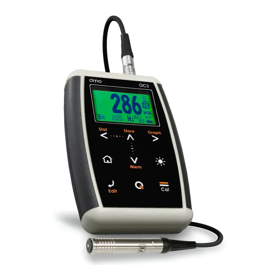
- Page 9 Figure 1.1: Front of the unit Graphic LCD display with LED backlight illumination Move Left key Move Up key / Manually store a value (Store) Move Right key Menu key / Enter and exit measure screen / Exit and return to menus (Home) Move Down key / Create new file in the Datalogger (Batch) Chapter 1...
- Page 10 Change backlight illumination key (On, Off, Auto) Enter key / Edit values on the measure screen (Edit) key: Power On and Shutdown (touch and hold for 2 seconds) / Make quick and short touches to activate special features 10. Calibration key 11.
- Page 11 The QC3 is powered by 2 (two) AA batteries that are placed in the battery compartment located in the back of the unit. To gain access to the battery compartment slide the cover as shown in figure 1.3-1 and gently push the extraction ribbon upward and slightly towards the right to release the batteries (figure 1.3-2).
- Page 12 Figure 1.4: Replace / Insert batteries Notes Always use new alkaline top brand batteries for extended battery life. Do not mix new and old batteries. Always replace both batteries. Rechargeable batteries type NiMH can be used but will result in less time of continuous operation. Chapter 1...
- Page 13 “Additional information, Error Messages”) The QC3 uses a type Lemo 0B 4-pin connector located on top of the unit. All dmq probes are provided with Cal-Tag technology allowing you to easily switch or replace probes. To connect the probe simply align the...
- Page 14 has three functions: When the unit is off, touch for 2 seconds to power on the unit. When the unit is on, touch for 2 seconds to shutdown the unit. With the unit on, making short touches to the will activate special functions described in each chapter of this manual.
- Page 15 The display contrast on all dmq units is digital. Touch the white dot located in the center of the vertical scrolling bar between the keys and a contrast window will open. Move your finger towards the top and or bottom of the dotted line to adjust the contrast on your display.
- Page 16 Sliding the finger to the left will unlock the keypad. Figure 1.9: Unlocking the keypad Important The keypad can only be locked and unlocked in the measuring screens. Chapter 1...
- Page 17 The QC3 measuring screen looks like this: Figure 2.1: Measuring screen 1. Number of (N) values counter / indicates number of values for real time group statistics 2. Average within group 3. Coating thickness value in the selected unit 4. Probe measuring icon (probe on sample) 5.
- Page 18 : Touch to create a new file or batch in the Datalogger. : Enter calibration mode (Page 11). : Changes the backlight illumination. : A short touch allows you to see statistics. Touch for 2 or more seconds to shutdown the unit. : Set display contrast.
- Page 19 The QC3 offers 3 modes of calibration that are explained in detail in this section of the user manual. The following table summarizes all 3 calibration modes: Abbreviation Name Base Samples Base & 1-Pt 1 a 9 ...
- Page 20 Text indicating required action Calibration mode When base measurements are taken, the screen will show the number of measurements. Then, depending on the calibration mode you are in, the unit will give you the option to move on to the following step. first line shows...
- Page 21 After the base calibration procedure is concluded, the unit will ask you to measure using a shim of a known thickness. For the calibration modes that do not require base calibration, the calibration process begins here. Follow on-screen instructions measure the shim of a known thickness value over the base.
- Page 22 Use the arrow keys to adjust the thickness to the nominal shim value and touch save. Figure 2.8: Shim calibration thickness adjustment screen Important When the probe is placed on the test piece simple, the probe action indicator (represented by an arrow), gets converted to a sand watch.
- Page 23 The instructions explained in this chapter apply to all of the menus in the unit. To scroll QC3 menu options use the cursor keys. When you reach the end of the menu and move to the next menu option it becomes circular as shown herein.
- Page 24 The main menu is the first list of options you will see when you exit the measuring screen and it includes the most important unit settings. Touch from the measuring screen to access this menu. Figure 3.3: Main menu Touch on Unit in the main menu to open the list of available units.
- Page 25 Touch to save the alarm value that you entered and to return to the previous menu. Figure 3.5: Alarm menu options Alarm types that you can choose include: Beep: Audible intermittent alarm type. Screen: Visible alarm that causes measurements to be displayed in dotted instead of regular numbers.
- Page 26 DataCenter. To view their contents simply double click on each file. For additional information on dmq DataCenter software refer to the manual included in the CD that you received with your QC3 or download the manual at http://www.demeq.com/Download.html...
- Page 27 Note The option of transferring values to a PC is only available in QC3 models with a Datalogger (DL). In the QC3 F and N values cannot be transferred. Touch on View Data to view the contents of the unit memory that appear in a grid format.
- Page 28 When the erase all action has been confirmed the following screens will be displayed: Figure 3.10: Erase progress screen When erasing is completed only empty cells will be displayed in the unit memory (grid). Touch on Capture to select the mode in which values will be stored in the Datalogger.
- Page 29 Free memory is followed by a number representing the remaining memory that is available to store data and is represented in number of cells. Touch on Free to view the remaining number of free cells and the free memory space as a percentage of the unit total memory. Figure 3.12: Remaining memory screens Touch on the Configure option to open the general...
- Page 30 Touch on Calib.Modes to select the calibration mode that you will be using to calibrate the unit. For details on each calibration mode see section 2.4 of this manual Use the keys to scroll all menu options and touch to select. Touch to exit.
- Page 31 key or the on-screen counter reaches 0.0, the sensitivity will return to its previous setting. The factory default setting is 50. Under special conditions we suggest that the sensitivity level be changed. Tips If the unit will operated using security gloves we recommend that the sensitivity level be raised.
- Page 32 The unit will shutdown automatically if no key is touched or no measurement is made after a time set by you. Touch on AutoOff to set the time before the unit automatically shuts down. Touch the keys to set the time and touch to save and exit.
- Page 33 Tips Contrast on LCD screens can change with temperature. Use the contrast option to compensate for changes caused by temperature to maintain optimal viewing conditions. Beep refers to the sounds that the unit makes when keys are touched and when the audible alarm is active. Touch to enable or disable the beep option.
- Page 34 When Continuous is enabled, the unit will measure for as long as the probe is not lifted. If Continuous is disabled, the unit takes individual readings each time the probe is coupled. To obtain measurements in this mode, the probe must be coupled and lifted each time. Select Information to view unit as well as probe information.
- Page 35 To switch between unit information screens touch the keys. To return to the main menu touch Select Probe Info to view all information as it relates to the probe that is connected to the unit. Touch any key to exit. Figure 3.22: Probe information screen QC3 models without a Datalogger can be changed to units with a Datalogger with the purchase of a model upgrade license from Demeq.
- Page 36 In order to obtain reliable measurements calibrate on the same type of base as the parts that you will actually be measuring. Highest accuracy is obtained when you are closest to the calibration point. This means that whenever possible, you should use shims that are as close as possible to the thickness that you expect to measure.
- Page 37 Measuring principle Magnetic induction / Eddy currents Probes QCS101 F / N / C (0 to 1500 µm) Materials (Ferrous) Iron, Steel, Magnetic Stainless Steel Materials (Non-Ferrous) Aluminum, Copper, Bronze, Brass Units Microns (µm) / Inches (Mil) Resolution 0 to 99.9 µm : 0.1 µm (QCS101 Probe) Above 100 µm : 1 µm 0 to 4.99 Mil : 0.01 Mil...
- Page 38 Measuring principle Magnetic induction / Eddy currents Measuring range 0 to 1500 µm, 0 to 60 Mil Resolution 0 to 99.9 µm : 0.1 µm Above 100 µm : 1 µm 0 to 4.99 Mil : 0.01 Mil Above 5.0 Mil : 0.1 Mil Materials (Ferrous) Iron, Steel, Magnetic Stainless Steel Materials (Non-Ferrous)
- Page 39 The QC3 was developed and manufactured for years of trouble free operation and even though the unit does not require special care the following precautions should be considered: Avoid contact with corrosive and abrasive substances. Do not clean the unit with solvents. ...
- Page 40 Description number QCM 300 High impact carrying case QCM 001 Silicone protective boot QCS 101F Standard ferrous probe (0 to 1500 µm) QCS 101N Standard non-ferrous probe (0 to 1500 µm) QCS 102F Low range ferrous probe (0 to 500 µm) QCS 102N Low range non-ferrous probe (0 to 500 µm)
- Page 41 Error messages may eventually open on your unit screen and are informational only. If one of these messages opens on your display follow the instructions described below and if the problem persists please send detailed report www.demeq.com/form_Support.html Figure A.2: System error message Error 1 Internal Error Cause...
- Page 42 Our website is a powerful customer support tool where you will find the latest information as it relates to your QC3 including: Application notes Manuals and brochures Software updates Model upgrade license information New accessories To download software updates to your QC3 you must have DataCenter installed on your PC.
Need help?
Do you have a question about the QC Series and is the answer not in the manual?
Questions and answers