Sign In
Upload
Download
Table of Contents
Contents
Add to my manuals
Delete from my manuals
Share
URL of this page:
HTML Link:
Bookmark this page
Add
Manual will be automatically added to "My Manuals"
Print this page
×
Bookmark added
×
Added to my manuals
Manuals
Brands
paladin Manuals
Construction Equipment
Bradco VRS48
Operator and parts manual
paladin Bradco VRS48 Operator And Parts Manual
Hide thumbs
1
2
Table Of Contents
3
4
5
6
7
8
9
10
11
12
13
14
15
16
17
18
19
20
21
22
23
24
25
26
27
28
29
30
31
32
33
34
35
36
37
38
39
40
41
42
43
page
of
43
Go
/
43
Contents
Table of Contents
Troubleshooting
Bookmarks
Table of Contents
Table of Contents
Preface
Safety Statements
General Safety Precautions
Equipment Safety Precautions
Decal Placement
Decals
General Information
Nomenclature
Attaching
Detaching
General Information
Operating Procedure
Maintenance and SERVICE
GENERAL MAINTENANCE - Every 8 / 100 / 500 Hours
Changing GEAR LUBE
DRUM Removal
Drum Installation
REPLACING Vibration ISOLATORS
REPLACING LEFT BEARINGS AND/OR Hubs
REPLACING Right BEARINGS AND/OR Hubs
Hydraulic MOTOR REPLACEMENT
Troubleshooting
Bolt Torque Specifications
Vibratory ROLLER SPECIFICATIONS
Limited Warranty
Smooth Vibratory ROLLER ASSEMBLIES
PADDED Vibratory ROLLER ASSEMBLIES
Spring Clamp Assembly
Frame Assemblies
Smooth DRUM ASSEMBLIES
Padded Drum Assemblies
Hub ASSEMBLIES
Hydraulic ASSEMBLY
Advertisement
Quick Links
1
Maintenance and Service
2
Drum Removal
3
Changing Gear Lube
4
Replacing Left Bearings And/Or Hubs
5
Hydraulic Motor Replacement
6
Hub Assemblies
Download this manual
OPERATOR'S AND PARTS MANUAL
SERIAL NUMBER: ___________________
MODEL NUMBER: ___________________
800-456-7100 I www.paladinattachments.com
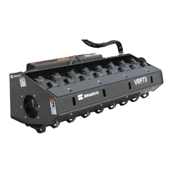
VIBRATORY ROLLER
503 Gay Street, Delhi, IA 52223, United States of America Copyright ©
Manual Number: OM695
Part Number: 75595
Rev. 4
10380
7-22-13-6
Table of
Contents
Previous
Page
Next
Page
1
2
3
4
5
Advertisement
Table of Contents
Need help?
Do you have a question about the Bradco VRS48 and is the answer not in the manual?
Ask a question
Questions and answers
Related Manuals for paladin Bradco VRS48
Construction Equipment paladin Bradco VRS73 Operator And Parts Manual
(43 pages)
Construction Equipment paladin Bradco VRS84 Operator And Parts Manual
(43 pages)
Construction Equipment paladin JRB SMART-LOC Operator's Manual
Coupler for excavators (31 pages)
Construction Equipment paladin McMillen X6075 Operator's Manual
Auger drives (29 pages)
This manual is also suitable for:
Bradco vrs66
Bradco vrs73
Bradco vrs84
Bradco vrp48
Bradco vrp66
Bradco vrp73
...
Show all
Bradco vrp84
40892
40893
40894
40895
40896
40897
40898
40899
Table of Contents
Print
Rename the bookmark
Delete bookmark?
Delete from my manuals?
Login
Sign In
OR
Sign in with Facebook
Sign in with Google
Upload manual
Upload from disk
Upload from URL


Need help?
Do you have a question about the Bradco VRS48 and is the answer not in the manual?
Questions and answers