
Related Manuals for Robur GA ACF HT


Summary of Contents for Robur GA ACF HT
- Page 1 Installation, use and maintenance manual Preassembled groups Modular heating unit and heater/chiller powered by gas and renewable energy...
- Page 2 The rights of those who have legitimately filed the registered trademarks contained within this publication are not affected. With the aim of continuously improving the quality of its products, Robur S.p.A. reserves the right to modify the data and contents of this Installation, use and maintenance manual without prior notice.
-
Page 3: Table Of Contents
INDEX OF CONTENTS Introduction System filling ............p. 30 ................p. 4 Fuel gas supply ............ p. 31 Recipients ..............p. 4 Combustion products exhaust ...... p. 32 Control device ............p. 4 3.10 Flue gas condensate discharge ..... p. 33 II Symbols and definitions ......... p. 4 3.11 Defrosting water drainage ...... -
Page 4: Iintroduction
First start-up = preassembled group commissioning op- CCI Controller (Comfort Controller Interface) = optional eration that can only and exclusively be performed by a Robur control device which lets you manage up to three TAC. modulating heat only GAHP units (A, WS, GS). - Page 5 Warnings systems and gas appliances, in compliance with „ For electrical connections exclusively use compli- the laws in force in the Country of installation. ant components and according to the specifica- tions provided by the manufacturer. Declaration of conformity „ Make sure the preassembled group and the indi- vidual GAHP/GA/AY modules of the same can not Upon completing installation, the installing firm be reactivated inadvertently.
-
Page 6: Iii.2 Compliance
Warnings and in compliance with current regulations. EN 12309 appliances for gas-fired heating and/or cool- ▶ „ Appliance maintenance and repairs may only be ing absorption. entrusted to firms legally authorised to work on EN 378 Refrigerating systems and heat pumps. ▶... -
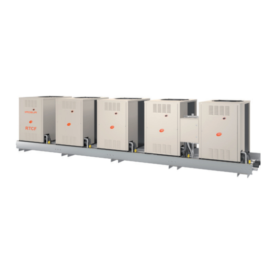
Page 7: Features And Technical Data
Features and technical data FEATURES AND TECHNICAL DATA For the characteristics of the individual modules (GAHP/ from 2 to 8 in the case of GAHP/GA and AY ▶ GA/AY units) that make up the RT__ Link, and of the con- Groups with aerothermal units must be installed exclu- trol devices (DDC, CCP/CCI, ...), refer to the respective sively outside, while others may be installed either in-... - Page 8 Features and technical data 7. (MET/NAT, G25, GPL/LPG) = fuel gas (natural gas or RTY, ...), based on composing modules (GAHP A/AR/ WS/GS, GA ACF/HR/TK/LB, AY00-120) LPG) 2. (2 or 3 digits) = cooling power, given by the sum of the 8.
- Page 9 Features and technical data Figure 1.1 Installation, use and maintenance manual – RT__ Link...
-
Page 10: Dimensions And Weights
Features and technical data DIMENSIONS AND WEIGHTS Figure 1.3 Position of water, gas and condensate discharge connections, for 4 pipes groups - Right side view The dimensions are given for the maximum foot- print configuration. The weights are given for the maximum weight configuration. - Page 11 Features and technical data Figure 1.4 Position of water, gas and condensate discharge connections, for 6 pipes groups - Top view Condensate discharge connection [1" F] (only for groups with more than one condensing unit). Sloping manifold, strictly connect on right side Gas connection [1 1/2"...
- Page 12 Features and technical data Figure 1.6 Dimensions and weights of ACF/A/AR preassembled group (with 2, 3, 4 and 5 units) - front view 1554 2314 1554 1554 3610 1554 1554 1554 4936 1554 1554 1554 1554 6490 960 kg 1920 kg 1440 kg 2410 kg...
- Page 13 Features and technical data Figure 1.7 Dimensions and weights of AY preassembled group (with 2, 3, 4 and 5 units) - front view 1554 1554 2314 1828 1554 1554 2314 1828 2 AY 330 kg 3 AY 450 kg 4 AY 580 kg 5 AY 700 kg Note: The weight refers to links configured with oversize circulators...
- Page 14 Features and technical data Figure 1.8 Dimensions and weights of ACF/A/AR + AY preassembled group (with 1+1, 1+2, 1+3, 1+4 units) - front and top view 1554 2314 1554 1554 3382 1+2 790 kg (*) 1+3 970 kg 1+4 1070 kg (*) (*) The weight refers to a 2 pipe link (silent ventilation, "S"), configured with oversize circulators The GAHP/GA + 1 AY00-120 configurations are re- placed by the Gitié...
- Page 15 Features and technical data Figure 1.9 Dimensions and weights of ACF/A/AR + AY preassembled group (with 1+5, 2+1 and 2+2 units) - front and top view 1554 1554 3610 1554 1554 3382 1+5 1210 kg (**) 2+1 1150 kg (*) 2+2 1270 kg (*) (*) The weight refers to a 2 pipe link (silent ventilation, "S"), configured with oversize circulators (**) The weight refers to a 4 pipe link (silent ventilation, "S"), configured on both circuits with oversize circulators Installation, use and maintenance manual –...
- Page 16 Features and technical data Figure 1.10 Dimensions and weights of ACF/A/AR + AY preassembled group (with 2+3, 2+4 and 2+5 units) - front and top view 1554 1554 1554 4936 1554 1554 1554 4936 2+3 1460 kg (*) 2+4 1560 kg (**) 2+5 1700 kg (**) (*) The weight refers to a 2 pipe link (silent ventilation, "S"), configured with oversize circulators (**) The weight refers to a 4 pipe link (silent ventilation, "S"), configured on both circuits with oversize circulators...
- Page 17 Features and technical data Figure 1.11 Dimensions and weights of ACF/A/AR + AY preassembled group (with 3+1, 3+2 and 3+3 units) - front and top view 1554 1554 1554 4936 1554 1554 1554 4936 3+1 1630 kg (*) 3+2 1750 kg (*) 3+3 1880 kg (**) (*) The weight refers to a 2 pipe link (silent ventilation, "S"), configured with oversize circulators (**) The weight refers to a 4 pipe link (silent ventilation, "S"), configured on both circuits with oversize circulators...
- Page 18 Features and technical data Figure 1.12 Dimensions and weights of ACF/A/AR + AY preassembled group (with 3+4 and 3+5 units) - front and top view 1554 1554 1554 1554 6490 1554 1554 1554 1554 6490 3+4 2060 kg (*) 3+5 2190 kg (*) (*) The weight refers to a 4 pipe link (silent ventilation, "S"), configured on both circuits with oversize circulators...
- Page 19 Features and technical data Figure 1.13 Dimensions and weights of ACF/A/AR + AY preassembled group (with 4+1, 4+2, 4+3 and 4+4 units) - front and top view 1554 1554 1554 1554 6490 1554 1554 1554 1554 6490 4+1 2120 kg (*) 4+2 2240 kg (**) 4+3 2380 kg (**) 4+4 2480 kg (**) The weight refers to a 2 pipe link (silent ventilation, "S"), configured with oversize circulators (**)
-
Page 20: Roma Valve
Features and technical data ROMA VALVE Preassembled groups equipped with water circulation with air vent valves, as detailed in the following Figure 1.14 p. 20 for the GAHP/GA units and in the following pumps are also equipped with a check valve, mounted Figure 1.15 ... -
Page 21: Independent Circulators Selector Switch Settings
Features and technical data INDEPENDENT CIRCULATORS For Wilo Yonos Para circulators (standard on RT__ Links al- SELECTOR SWITCH SETTINGS ready provided with circulators) the selector switch must be set as shown in Figure 1.17 p. 21 . In the RT__ Links already provided with circulators, each circulator is provided with a selector switch to determine Figure 1.17 ... -
Page 22: Electrical Specifications
Features and technical data ELECTRICAL SPECIFICATIONS Group electrical panel Figure 1.18 Group electrical panel Group electrical panel (QEG) switch disconnector "ID01" unit magnetothermic breaker TR Transformer 230/24 Vac "ID02" unit magnetothermic breaker M9 Transformer primary fuse "ID03" unit magnetothermic breaker M2 Condensate heating resistance protection fuse "ID04"... -
Page 23: 1.11 Technical Data
The DDC controller is able to control appliances, a sin- (modulating GAHP unit) gle GAHP unit, or even several Robur GAHP/GA/AY units in cascade, only in ON/OFF mode (non modulating). For The CCP/CCI control is able to control up to 3 GAHP units... -
Page 24: Minimum Clearance Distances
Transport and positioning a room phenomenon. Machine room requirements for hydrothermal or The aerothermal RT__ Links include devices geothermal RT__ Links equipped with finned coils and fan, approved for outdoor installation. Hydrothermal and geothermal RT__ Links (made up by „ Do not install the aerothermal RT__ Links inside a GAHP GS/WS modules) and the AY00-120 boilers links as room, not even if it has openings. -
Page 25: Heating Engineer
1” F For detailed information, please refer to the Design ▶ Manual and/or contact the Robur technical service. The hydraulic connections are arranged on the right side of the preassembled unit but can be moved to the left Primary and secondary circuit... - Page 26 Heating engineer condensation discharge which is sloping and therefore preassembled group: can only be made from the right side. on water piping, both output and input ▶ (Figures 1.2 p. 10 , 1.3 p. 10 , 1.4 p. 11 , 1.5 p. 11 ). „...
- Page 27 Heating engineer Figure 3.2 Example of hydraulic system diagram for connection of 1 RTCR, version without circulating pumps Anti-vibration connections Safety valve (3 bar) Pressure gauge Water pump (primary circuit) Flow regulator valve Hydraulic separator (with air vent valve and drain tap) Water filter 10 Expansion tank of the secondary circuit Shut-off valve...
- Page 28 Heating engineer Figure 3.3 Example of hydraulic system diagram for connection of 2 RTCR, version with circulating pumps Anti-vibration connections Hydraulic separator (with air vent valve and drain tap) Water filter Expansion tank of the secondary circuit Shut-off valve Water pump (secondary circuit) Expansion tank of the primary circuit DDC control panel Safety valve (3 bar)
-
Page 29: Antifreeze Function
Heating engineer Figure 3.4 Example of hydraulic system diagram for connection of 2 RTCR, version without circulating pumps Anti-vibration connections Safety valve (3 bar) Pressure gauge Water pump (primary circuit) Flow regulator valve Hydraulic separator (with air vent valve and drain tap) Water filter 10 Expansion tank of the secondary circuit Shut-off valve... -
Page 30: System Water Quality
Heating engineer propylene glycol only. oxidation phenomena. Glycol effects Type of antifreeze glycol The Table 3.2 p. 30 shows, indicatively, the effects of us- Inhibited type glycol is recommended to prevent ing a glycol depending on its %. Table 3.2 Technical data for filling the hydraulic circuit Water-glycol mixture freezing Percentage of increase in pressure Glycol %... -
Page 31: Fuel Gas Supply
Heating engineer Gas pipes sizing preassembled group and open the first vent valve (Figure 1.14 p. 20 , detail E). The gas pipes must not cause excessive pressure drops 5. Close the first vent valve and open the sectioning and, consequently, insufficient gas pressure for the appli- valve on the delivery of the preassembled group. -
Page 32: Combustion Products Exhaust
Heating engineer Table 3.4 Network gas pressure Gas supply pressure G25.1 G25.3 G2,350 Product Countries of destination category [mbar] [mbar] [mbar] [mbar] [mbar] [mbar] [mbar] [mbar] AL, BG, CY, CZ, DK, EE, FI, GR, HR, IT, LT, MK, NO, RO, SE, SI, SK, TR 2H3B/P AT, CH BG, CH, CZ, ES, GB, HR, IE, IT, LT, MK,... -
Page 33: 3.10 Flue Gas Condensate Discharge
Charging the siphon evacuated in compliance with current regulations. Robur uses condensate collection siphons with float, which blocks the passage of fumes and odours deriving Condensate acidity and exhaust regulations therefrom in case the equipment remains turned off for a... -
Page 34: Electrical Systems
Electrical installer „ The preassembled group must be connected to an request of the preassembled group. effective earthing system, installed in compliance GAHP/GA/AY modules with regulations in force. „ It is forbidden to use gas pipes as earthing. As far as the individual GAHP/GA/AY modules be- longing to the preassembled group are concerned, Cable segregation read the relevant warnings and dangers in their re-... -
Page 35: Adjustment And Control
Electrical installer How to connect the power supply Figure 4.3 Single phase power supply electrical connection 230 V 1N - 50 Hz To connect the multipole power cable (Figures 4.2 p. 35 and 4.3 p. 35 ): 1. Access the terminal blocks in the electrical panel of the group (Paragraph 4.2 ... - Page 36 Electrical installer Table 4.1 CAN bus cables type Cable name Signals / Color Maximum length Note Robur Optional code OCVO008 ROBUR NETBUS H = BLACK L = WHITE GND = BROWN 450 m Honeywell SDS 1620 BELDEN 3086A H = BLACK...
- Page 37 Electrical installer CAN bus cable sections). Figure 4.5 Connection of the CAN bus cable to the electronic board Figure 4.6 Connection of the CAN bus cable to the control panel GND H GND H JUMPER J21 JUMPER J21 SCH Electronic board GND Common data Data signal LOW Data signal HIGH DDC Direct Digital Controller...
- Page 38 Electrical installer must be open, as shown in detail B of Figure 4.5 p. 37 . Figure 4.8 Example of CAN network with 7 nodes (1 DDC + 2 appliances connected on a single hydraulic circuit) QEG2 Terminal node connection to DDC QEG2 Second appliance group electrical panel CAN bus cable (not supplied - see table)
-
Page 39: Water Circulation Pumps
Electrical installer WATER CIRCULATION PUMPS In RT__ Link without circulating pumps, electrical connec- tions must be made (both for power supply and control) In RT__ Links with circulating pumps, the individual inde- of the common water circulation pump of the primary wa- pendent circulating pumps (1 or 2 for each GAHP/GA/AY ter circuit, as shown in the diagrams in Figures 4.9 ... -
Page 40: First Start-Up
Water, electrical and gas systems suitable for the re- ▶ out by a Robur TAC. NEITHER the user NOR the in- quired capacities and equipped with all safety and stallation technician is authorised to perform such control devices required by the regulations in force. -
Page 41: Electronic Adjustment On The Appliance - Menus And Parameters
If you need to connect/disconnect the power sup- First start-up may exclusively be carried out by a ply, see Paragraph 7.1 p. 42 . Robur TAC (Chapter 5 p. 40 ). Checks before switching on Never power the appliance off while it is run-... -
Page 42: Efficiency
Maintenance „ DDC or CCI power supply (through transformer) connected control device (DDC or CCP/CCI). For in- „ water circuit ready structions, see the control device Manual. How to switch on/off Do not modify complex settings To turn on/off the RT__ Link see the Manual of the connected control device (DDC or CCP/CCI). -
Page 43: Pre-Emptive Maintenance
Maintenance AY modules belonging to the preassembled group, consult their respective Manuals (attached). PRE-EMPTIVE MAINTENANCE pre-emptive maintenance, comply with recommendations in Table 7.1 p. 43 . Table 7.1 GAHP GS/ GAHP A AY00-120 GA ACF GAHP-AR Guidelines for the preventive maintenance operations visually check of the general condition of the unit and of its √... -
Page 44: Restarting A Locked-Out Unit
Maintenance If it is a permanent error or warning the appliance stops. winter, ensure at least one of the following two conditions: 1. antifreeze function active (Paragraph 3.4 p. 29 ) Refer to the operating codes tables in the Manuals 2. sufficient antifreeze glycol (Paragraph 3.5 p. 29 ) of the individual units or in the DDC/CCI/CCP con- Prolonged periods of inactivity trols Manuals (attachments) for diagnostic. -
Page 45: Diagnostics
Diagnostics DIAGNOSTICS APPLIANCES/CONTROLLERS Refer to the operating codes tables in the Manuals of the individual units or in the DDC/CCI/CCP con- trols Manuals (attachments) for diagnostic. CIRCULATING PUMPS See Appendix 9.2 p. 52 . Installation, use and maintenance manual – RT__ Link... -
Page 46: Appendices
Appendices APPENDICES WIRING DIAGRAMS AND INTERNAL WIRINGS Figure 9.1 Diagram 1 N0-M2 F0-M2 AE Power supply input terminals "ID05" unit magnetothermic breaker AT Antifreeze thermostat Group electrical panel (QEG) switch disconnector CAN 3-pole connector for CAN bus network connection 2-pole 24 Vac connector for service use CHR Condensation heating resistance M9 Transformer primary fuse "ID00"... - Page 47 Appendices Figure 9.2 Diagram 2 N0-M2 F0-M2 See the Figure 9.1 p. 46 legend. • the TAC must reset from the board, to progression, the enumeration of the board ID of all units; IEP Interior of the electrical panel • on appliances with 2 units, only ID00 + ID01 units will be present CLOSED jumpers (from factory): keep CLOSED only if ID00 is a (with jumpers predefined as in the example) TERMINAL node on the CAN network...
- Page 48 Appendices Figure 9.3 Diagram 3 N0-M2 F0-M2 See the Figure 9.2 p. 47 legend. MA Appliance terminal block PM Water pump < 700 W KPt Thermostat with setpoint calibration of DHW tank (not supplied) PMR Recovery exchanger pump KPs Thermostat calibrated at 35 °C with capillary tube in the lower TER Power supply terminal block 230 Vac part of the DHW tank (not supplied) [to be provided in the event NOTE...
- Page 49 Appendices Figure 9.4 Diagram 4 N0-M2 F0-M2 See the Figure 9.3 p. 48 legend. Installation, use and maintenance manual – RT__ Link...
- Page 50 Appendices Figure 9.5 Diagram 5 N0-M2 F0-M2 See the Figure 9.3 p. 48 legend.
- Page 51 Appendices Figure 9.6 Diagram 6 See the Figure 9.2 p. 47 legend. IEP Interior of the electrical panel RSTN Phases/neutral Installation, use and maintenance manual – RT__ Link...
-
Page 52: Circulating Pumps
Appendices CIRCULATING PUMPS To access the circulating pumps, remove the plastic cover (for GAHP/GA, Figure 1.14 p. 20 ), or remove the front panel of the AY00-120 units (Figure 1.15 p. 20 ). Table 9.1 Wilo Yonos pump block signalings Code Fault Cause Remedial action Insufficient mains voltage Supply voltage too low on the mains side... - Page 56 Robur mission Robur is dedicated to dynamic progression in research, development and promotion of safe, environmentally-friendly, energy-efficiency products, through the commitment and caring of its employees and partners. Robur S.p.A. advanced technologies for air conditioning via Parigi 4/6 24040 Verdellino/Zingonia (BG) Italy +39 035 888111 - F +39 035 884165 www.robur.it robur@robur.it...
Need help?
Do you have a question about the GA ACF HT and is the answer not in the manual?
Questions and answers