Table of Contents
Advertisement
Quick Links
IM No. : IM/V/0021, Rev. 2
Date: 06.11.2017
Page 1 of 6
MOUNTING, OPERATING, TESTING & MAINTENANCE INSTRUCTIONS
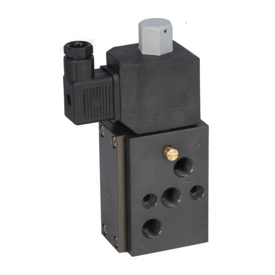
FOR ROTEX 5/2, 3/2 CONVERTIBLE NAMUR SOLENOID VALVE
MODEL 51424, 51424LW, 51424IS
ROTEX retains all rights to this publication.
All details within this manual and the catalogue are subject to change without manner.
ROTEX will not be responsible for any damage whatsoever arising from the use of the Solenoid Valve, due to misuse or
incorrect installation or misinterpretation of the information contained herein.
SPECIFICATION OF STANDARD SOLENOID VALVE
CONNECTION
External
VALVE TYPE
Inlet
Outlet
Exhaust
Outlet
Exhaust
Pilot Vent
Pilot Inlet
51424
1
2 (NAMUR)
3
4 (NAMUR)
5
6
-
A)
OPERATING PRINCIPLE
On de-energized condition of the solenoid, pressure applied at the inlet port, a part of media from the inlet port # 1 is drawn
through the internal pilot passage which is blocked under Plunger. In case of External Pilot Operated Valve the external
pilot port # 7 is drawn through the external pilot passage is blocked by plunger. In this state the Inlet port # 1 & Outlet port
# 4 is connected. Outlet port # 2 & Exhaust port # 3 are connected; Exhaust Port # 5 is blocked.
On energized condition of the solenoid, Plunger moves up and media from pilot passage acts on the piston assembly thus,
poppet assembly goes down and connecting. In this state Inlet port # 1 & Outlet port # 2 is connected. Outlet Port # 4 &
Exhaust port # 5 are connected; Exhaust port # 3 is blocked.
NOTE: IN CASE WHEN THE VALVE IS OPERATED AS EXTERNAL PILOT OPERATED VALVE, THE PILOT AIR
PRESSURE SHOULD BE MINIMUM 2 bar OR > MAIN FLUID PRESSURE WHICHEVER IS HIGHER.
Advertisement
Table of Contents

Related Manuals for Rotex 51424


Summary of Contents for Rotex 51424
- Page 1 All details within this manual and the catalogue are subject to change without manner. ROTEX will not be responsible for any damage whatsoever arising from the use of the Solenoid Valve, due to misuse or incorrect installation or misinterpretation of the information contained herein.
- Page 2 IM No. : IM/V/0021, Rev. 2 Date: 06.11.2017 Page 2 of 6 IDENTIFICATION ON THE SOLENOID VALVE VALVE MARKING Label on the ROTEX Solenoid Valve shows the following details: Logo + Name & address of the Manufacturer Valve Type / Code 51424 = Valve Model...
- Page 3 To convert valve from 5/2 to 3/2, remove disk at Port-4 and refix the same after turning 180º. (Refer Photo-XX). 51424 can be operated with 6 Watt / 8 Watt Solenoid. 51424LW can be operated with 2 Watt Solenoid. 51424IS can be operated with Low Power Intrinsically Safe Solenoid.
- Page 4 It is recommended to replace complete set of O Ring even if one of the O Ring is damaged. This is to ensure trouble free operation of the valve and will avoid its premature failure. Using Grease other than Silicon base Molykote M55 will lead to premature failure of O Rings of the ROTEX Solenoid valve. ...
- Page 5 In case of difficulty you should contact the Agent, Distributor or ROTEX directly. Using ROTEX genuine spares will guarantee you trouble free operation and will avoid premature failure. TO REPLACE SOLENOID Open dome nut and pull out solenoid Replace new solenoid ensuring the construction, voltage and current meets the requirements.
- Page 6 (New Design Plunger) Screw Photo – 6 Photo – 7 Photo – 8 Contact: ROTEX AUTOMATION LIMITED 987/11, GIDC, MAKARPURA, VADODARA – 390010, INDIA Tel. : +91 265 2638136, 2638746, 2638795 Fax : +91 265 2638130 E-mail : rotexbrd@rotexautomation.com Website : www.rotexautomation.com...
Need help?
Do you have a question about the 51424 and is the answer not in the manual?
Questions and answers