
Related Manuals for PEMTECH PT395


Summary of Contents for PEMTECH PT395
- Page 1 Model PT395 Stand Alone Sensor For Combustible Hydrocarbons Revision 6 Operator’s Manual Pem-Tech, Inc. Houston, Texas U.S.A...
-
Page 2: Table Of Contents
Description, General Information Selective response to different Combustible Gases Adjust alarm set points Setting Low & High Alarm Levels MAINTENANCE Factors affecting sensor accuracy Routine maintenance Sensor Inspection Sensor Sensitivity Sensor Replacement Spare Parts PT395 Series LEL Sensor Rev 6... - Page 3 Please call factory for RMA (return merchandise authorization) number before sending any equipment for repair or replacement. PT395 Series LEL Sensor Rev 6...
-
Page 4: Service Policy
For this an additional charge may be applicable. NOTE: 1. For all the repairs under warranty, serial number must be legible on the items being repaired. 2. Shipping point is FOB Houston. PT395 Series LEL Sensor Rev 6... - Page 5 . Silicone based lubricants must never be used. Follow the wiring instruction for proper and safe operation under normal conditions. Be sure that all wiring complies with NEC and all local ordinances. PT395 Series LEL Sensor Rev 6...
-
Page 6: Specifications
Low, High, & Malfunction Relay contacts Normally open or Normally closed, Form “C” type. Relay rating: 1 amps @ 30VDC VISUAL ALARM Alarm LED indicators INDICATORS Amber for Low alarm, Red for High alarm & Red for Malfunction PT395 Series LEL Sensor Rev 6... -
Page 7: Overview
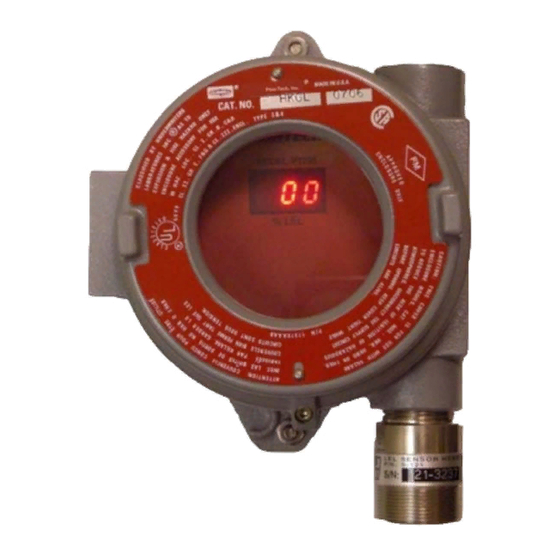
Overview Model PT395 is a single point fixed sensor for the detection combustible hydrocarbon vapors in ambient air. Detection range is 0 – 100 % LEL (Lower Explosive Limit). PT395 displays the gas concentration and transmits a linear 4- 20mA analog output signal that is proportional to the gas concentration displayed. -
Page 8: Transmitter Board Assembly
Figure 2. Model PT395 Transmitter and connection board assembly PT395 Series LEL Sensor Rev 6... -
Page 9: Connection Board Assembly
These wires are connected as follows: R Red wire (Sensor Positive 2 VDC Supply) B Black Wire (Sensor Ground) G White Wire (Sensor signal out) For proper operation these wires must be connected as noted above. PT395 Series LEL Sensor Rev 6... -
Page 10: Dc Power And 4-20Ma Signal Output
Figure 3. Connection to DC Power Supply and PLC input module PT395 Series LEL Sensor Rev 6... -
Page 11: Low And High Alarms
Wiring Diagram: Low and High Alarms Figure 4. Connection to Alarm warning devices PT395 Series LEL Sensor Rev 6... -
Page 12: Installation
Installation Refer to figure 5 for model PT395 explosion proof enclosure for mounting and conduit connection. Figure 5. Explosion proof sensor enclosure. Follow steps below for installation. Remove the enclosure cover and un-plug the transmitter board by simply moving the thumb screws in counter-clockwise direction until they have loosen up. - Page 13 Reference Wire size Table Wire Size Max Distance / Wire length 14 AWG 3300 Feet 18 AWG 1400 Feet 16 AWG 2200 Feet 20 AWG 900 Feet Note: The table above is for reference only PT395 Series LEL Sensor Rev 6...
-
Page 14: Start Up
If calibration is required then follow the steps in the Calibration procedure. PT395 Series LEL Sensor Rev 6... -
Page 15: Normal Operation
+ 4 = Analog output (mA) Detection Range Formula to convert mA to gas reading: ( mA Output - 4 ) x Detection Range = gas_reading (Note: Detection Range is the full scale range of the sensor) PT395 Series LEL Sensor Rev 6... -
Page 16: Alarm Conditions
The high alarm (red) LED indicator lights up and the high alarm relay is energized. Fault (Sensor Fail) PT395 is in Fault (Malfunction) condition when the sensor assembly malfunctions. In Fault condition the 4-20mA output generated would be less than 1.0 mA. PT395 Series LEL Sensor... -
Page 17: Resetting Alarms
Continue to hold the magnet to the cover and the sensor will display “rSt” (short for RESET) on the LED display for few seconds. Figure 6. Magnetic Sensor Position 4 o’clock to RESET alarms and to adjust alarm levels / set points. PT395 Series LEL Sensor Rev 6... -
Page 18: Calibration
1.5 LPM (liters per minute) See Figure 8 Model PT395 sensor can be auto calibrated without removing the enclosure cover and declassifying the zone. A magnet tool is used to activate the internal switch to initiate the calibration. Once the calibration is initiated the alarm relay will be deactivated and the 4-20mA analog signal will be held at approximately 2mA to avoid any false alarm. - Page 19 Also refer to “Sensor calibration Flow Chart” for quick calibration review and “Calibration Error and remedies” Figure 7. Magnetic switch position to activate Calibrate Mode PT395 Series LEL Sensor Rev 6...
- Page 20 Figure 8. Sensor Calibration using flow regulator and calibration adapter. PT395 Series LEL Sensor Rev 6...
- Page 21 The sensor detected the flow of the calibration gas but the sensitivity to the gas is not consistent. Double check the wires connecting the sensor head. And repeat the calibration procedure after few minutes. If same error reoccurs the sensor head assembly must be replaced. PT395 Series LEL Sensor Rev 6...
-
Page 22: Sensor Calibration
ADJ is being displayed Remove Calib Gas when display Display flashes rapidly for about Starts flashing rapidly 10 seconds. Returns to normal (approximately 5 times per operation when sensor has second) cleared Sensor Calibrated Successfully PT395 Series LEL Sensor Rev 6... - Page 23 Sensor operating characteristics Description The model PT395 series LEL Sensor uses a matched pair of catalytic bead for the detection of combustible vapors in air. The sensor transmitter provides a liner 4 to 20mA output signal corresponding to 0 to 100% LEL gas concentration. Also the %LEL is displayed on the 3 digit LED display on the transmitter board.
- Page 24 0.75 Ethyl Acetate 0.55 Ethylene 0.70 Hydrogen 1.00 Iso-Butane 0.60 Iso-butyl Alcohol 0.25 Iso-Octane 0.40 Iso-Pentane 0.50 Iso-Propyl Alcohol 0.60 Methane 1.00 Methanol 1.00 Methyl Ethyl Ketone 0.50 n-Butane 0.60 n-Heptane 0.45 n-Hexane 0.50 PT395 Series LEL Sensor Rev 6...
- Page 25 In such events, the sensor must be allowed to clear for at least one (1) hour and then re-calibrated to ensure proper operation. PT395 Series LEL Sensor Rev 6...
-
Page 26: Adjust Alarm Setpoints
ADJUST ALARM SETPOINTS PT395 has two (2) fully programmable relays for Low and High alarms. The third relay is used for Sensor Fault or malfunction. The alarm levels can be set anywhere between 0 and the full scale range of the sensor. Also they can be configured as Latching or non-latching. - Page 27 Relay will stay active even after the gas concentration falls below the preset alarm level. The alarm relay must be manually reset using the internal magnetic switch To RESET alarms refer to section “Resetting Alarms” Non-Latching Factory defaults alarm relay settings are PT395 Series LEL Sensor Rev 6...
-
Page 28: Maintenance
Be sure to remove the protective shield when finished. Routine Maintenance Model PT395 Sensors do not require routine maintenance. However, the sensors should be inspected periodically to ensure proper operation. Sensor Inspection Keep the sensor flame arrestor clean. -
Page 29: Sensor Replacement
9. Power up the sensor, if disconnected , and let the sensor warm-up as indicated in the “Start up” section in this manual. 10. Calibrate the sensor. Follow the instructions in calibration procedure in this manual. PT395 Series LEL Sensor Rev 6... -
Page 30: Spare Parts
C-800 Magnet Tool for Calibration and alarm adjustment C-251 Calibration Adapter with tubing 14-105 Disposable calibration gas bottle 103 Liters 50% LEL (2.5% Methane in air) 14-165 1.5 Liters per minute (LPM) flow regulator PT395 Series LEL Sensor Rev 6... - Page 31 EN 60079-0 (2006), EN 60079-1 (2007), and EN 13980 (2002) Final Declaration I, the undersigned, hereby declare that the product(s) specified above conforms to the listed Directive(s) and standard(s). Rizwan Mistry Director of Engineering PT395 Series LEL Sensor Rev 6...
Need help?
Do you have a question about the PT395 and is the answer not in the manual?
Questions and answers