
Related Manuals for PEMTECH PT295


Summary of Contents for PEMTECH PT295
- Page 1 Gas Detection Technology Model PT295 Stand Alone Toxic Sensor Revision 5.1 Operator’s Manual Pem-Tech, Inc. Houston, Texas U.S.A www.pem-tech.com...
-
Page 2: Table Of Contents
Setting Low & High Alarm Levels MAINTENANCE Factors affecting sensor accuracy Routine maintenance Sensor Inspection Sensor Sensitivity Sensor Replacement Spare Parts Part Numbers for transmitter boards And sensor head assembly Part Numbers for recommended calibration gases PT295 Series Toxic Sensor Rev 5.1... -
Page 3: Notice And Limited Warranty
Please call factory for RMA (return merchandise authorization) number before sending any equipment for repair or replacement. PT295 Series Toxic Sensor Rev 5.1... -
Page 4: Service Policy
For this an additional charge may be applicable. NOTE: 1. For all the repairs under warranty, serial number must be legible on the items being repaired. 2. Shipping point is FOB Houston. PT295 Series Toxic Sensor Rev 5.1... - Page 5 . Silicone based lubricants must never be used. • Follow the wiring instruction for proper and safe operation under normal conditions. Be sure that all wiring complies with NEC and all local ordinances. PT295 Series Toxic Sensor Rev 5.1...
-
Page 6: Specifications
Maximum of 300 Ohms loop resistance DISPLAY 3 Digit LED display. ALARM RELAY Form “C” type Alarm Relay contacts Relay rating: 2 amps @ 30VDC or 125 VAC Fully programmable, Normally open or Normally closed, PT295 Series Toxic Sensor Rev 5.1... -
Page 7: Overview
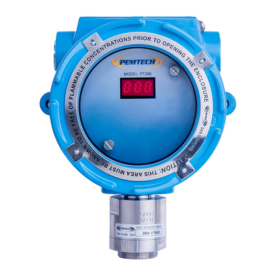
Overview Model PT295 is a single point fixed sensor for the detection of toxic gases in ambient air. Table I lists the target gases and the detection ranges. PT295 displays the gas concentration and transmits a linear 4-20mA analog output signal that is proportional to the gas concentration displayed. -
Page 8: Target Gases And Detection Ranges
50 ppm Nitrogen Dioxide (NO 20 ppm Nitric Oxide (NO) 100 ppm Hydrogen Chloride (HCL) 100 ppm Chlorine (CL 10 ppm Oxygen deficiency (O2) 25 % Hydrogen (H 200 ppm Methyl Mercaptan (CH 100 ppm PT295 Series Toxic Sensor Rev 5.1... -
Page 9: Transmitter Board Assembly
/ termination board. Figure 2. Model PT295 Transmitter and connection board assembly PT295 Series Toxic Sensor Rev 5.1... -
Page 10: Connection Board Assembly
B Black wire (Sensor -5VDC Supply) Note: Oxygen sensor head has only 2 wires (Black and white). Thus only these 2 wire connections are required For proper operation these wires must be connected as noted above. PT295 Series Toxic Sensor Rev 5.1... -
Page 11: Dc Power And 4-20Ma Signal Output
Figure 3. Connection to DC Power Supply and PLC input module PT295 Series Toxic Sensor Rev 5.1... -
Page 12: Low And High Alarms
Wiring Diagram: Low and High Alarms Figure 4. Connection to Alarm warning devices PT295 Series Toxic Sensor Rev 5.1... -
Page 13: Installation
Installation Refer to figure 5 for model PT295 explosion proof enclosure for mounting and conduit connection. Figure 5. Explosion proof sensor enclosure. Follow steps below for installation. Remove the enclosure cover and un-plug the transmitter board by simply moving the thumb screws in counter-clockwise direction until they have loosen up. - Page 14 Reference Wire size Table Max Distance / Wire length Wire Size 14 AWG 3300 Feet 1400 Feet 18 AWG 16 AWG 2200 Feet 20 AWG 900 Feet Note: The table above is for reference only PT295 Series Toxic Sensor Rev 5.1...
-
Page 15: Start Up
If calibration is required then follow the steps in the Calibration procedure. PT295 Series Toxic Sensor Rev 5.1... -
Page 16: Normal Operation
+ 4 = Analog output (mA) Detection Range Formula to convert mA to gas reading: ( mA Output - 4 ) x Detection Range = gas_reading (Note: Detection Range is the full scale range of the sensor) PT295 Series Toxic Sensor Rev 5.1... -
Page 17: Alarm Conditions
18 %, the relay will be energized if the oxygen level is at or falls below 18% Fault (Sensor Fail) PT295 is in Fault (Malfunction) condition when the sensor assembly malfunctions. In Fault condition the 4-20mA output generated would be less than 1.0 mA. The sensor displays “FLt”... -
Page 18: Resetting Alarms
Continue to hold the magnet to the cover and the sensor will display “rSt” (short for RESET) on the LED display for few seconds. Figure 6. Magnetic Sensor Position 4 o’clock to RESET alarms and to adjust alarm levels / set points. PT295 Series Toxic Sensor Rev 5.1... -
Page 19: Calibration
Model PT295 sensor can be auto calibrated without removing the enclosure cover and declassifying the zone. A magnet tool is used to activate the internal switch to initiate the calibration. - Page 20 Do not remove the calibration gas while Adj is being displayed. Remove the gas only when the adjustment is completed and the display is rapidly flashing with calibration gas value. PT295 Series Toxic Sensor Rev 5.1...
- Page 21 If no gas is detected within 60 seconds the sensor aborts calibration and will display E-3 error code “Calibration Time Out” for few seconds before returning to normal operation. PT295 Series Toxic Sensor Rev 5.1...
-
Page 22: Recommended Calibration Gases
100 ppm Hydrogen balanced in Air Hydrogen Chloride 50 ppm HCL balanced in air Nitric Oxide 50 ppm NO balanced in air Nitrogen Dioxide 10 ppm NO2 balanced in air Chlorine 5 ppm CL2 air balanced PT295 Series Toxic Sensor Rev 5.1... - Page 23 ½ LPM Flow Regulator Calibration Adapter with tubing Calibration Gas cylinder Figure 8. Sensor Calibration using flow regulator and calibration adapter. PT295 Series Toxic Sensor Rev 5.1...
- Page 24 The sensor detected the flow of the calibration gas but the sensitivity to the gas is not consistent. Double check the wires connecting the sensor head. And repeat the calibration procedure after few minutes. If same error reoccurs the sensor head assembly must be replaced. PT295 Series Toxic Sensor Rev 5.1...
-
Page 25: Calibration Errors And Remedies
ADJ is being displayed Remove Calib Gas when display Display flashes rapidly for about Starts flashing rapidly 10 seconds. Returns to normal (approximately 5 times per operation when sensor has second) cleared Sensor Calibrated Successfully PT295 Series Toxic Sensor Rev 5.1... -
Page 26: Calibration Flow Chart
ADJUST ALARM SETPOINTS PT295 has a fully programmable relay for alarms. The alarm level can be set anywhere between 0 and the full scale range of the sensor. Also they can be configured as Latching or non-latching. The relay have Form “C” type contacts. -
Page 27: Adjust Alarm Set Points
Relay will stay active even after the gas concentration falls below the preset alarm level. The alarm relay must be manually reset using the internal magnetic switch To RESET alarms refer to section “Resetting Alarms” Non-Latching Factory defaults alarm relay setting is PT295 Series Toxic Sensor Rev 5.1... -
Page 28: Maintenance
Be sure to remove the protective shield when finished. Routine Maintenance Model PT295 Sensors do not require routine maintenance. However, the sensors should be inspected periodically to ensure proper operation. Sensor Inspection Keep the sensor flame arrestor clean. -
Page 29: Sensor Replacement
9. Power up the sensor, if disconnected , and let the sensor warm-up as indicated in the “Start up” section in this manual. 10. Calibrate the sensor. Follow the instructions in calibration procedure in this manual. PT295 Series Toxic Sensor Rev 5.1... -
Page 30: Spare Parts
S-61-106 S-131 Nitric Oxide (NO) S-61-107 S-152 Nitrogen Dioxide (NO S-61-108 S-440 Hydrogen Chloride (HCL) S-61-109 S-162 Chlorine (CL S-61-110 S-359 Methyl Mercaptan (CH S-61-111 S-798 Sulfur Dioxide (SO S-61-112 S-130 Range 50 ppm PT295 Series Toxic Sensor Rev 5.1... -
Page 31: Part Numbers For Recommended Calibration Gases
14-085 50 ppm Nitric Oxide in Air 14-120 10 ppm Nitrogen Dioxide in Air 14-110 50 ppm Hydrogen Chloride in Air 14-125 5 ppm Chlorine in air 14-131 10 ppm Methyl Mercaptan (CH 14-032 PT295 Series Toxic Sensor Rev 5.1... - Page 32 The signature on this document authorizes the distinctive European mark to be applied to the equipment described. Authorized Signature: Rizwan Mistry Director of Engineering Date: August 29, 2014 PT295 Series Toxic Sensor Rev 5.1...
Need help?
Do you have a question about the PT295 and is the answer not in the manual?
Questions and answers