
Subscribe to Our Youtube Channel
Related Manuals for ILVE AG60


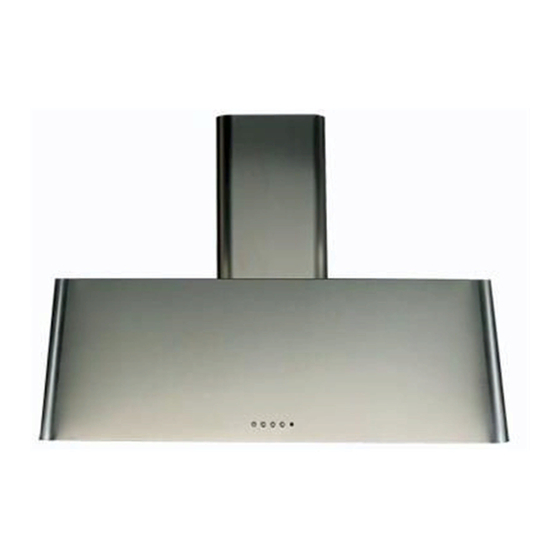
Summary of Contents for ILVE AG60
- Page 1 HOODS AG60 - AG70 - AG90 - AG100 - AG120 - AG150 USER – Use and Maintenance INSTALLER - Installation manual cod. EI33960380000EN 08/2021...
- Page 3 INDEX USER (4-13) USEFUL INFORMATION IMPORTANT SAFETY WARNING INSTRUCTIONS FOR USE CLEANING AND MAINTENANCE PERIODS OF INACTIVITY ORDINARY MAINTENANCE - replacement of the spotlight INSTALLER (14-31) IMPORTANT SAFETY WARNINGS INSTALLATION IMPORTANT SAFETY WARNINGS INSTALLATION...
-
Page 4: Useful Information
We remain at your full disposal for any further information that you may require, or if you have any problems in understanding any contents of this booklet. ILVE S.p.a. Via Antoniana, 100 35011 Campodarsego (PD) Italy tel. +39 049 9200990 - fax +39 049 9201010 SEND MAIL: mail@ilve.com... - Page 5 USER LEGEND ICON Read this manual carefully before installing or using the equipment. The manual contains some warning or danger symbols: Danger! Situation of immediate danger or dangerous si- tuation that might cause injuries or death. Read the instruction manual Useful advice and information Reference to another chapter ATTENTION:...
-
Page 6: Important Safety Warnings
• ILVE S.p.a. (hereinafter referred to as “the Manufactu- rer”) denies any and all liability due to the failure to comply with the instructions below, including... - Page 7 USER IMPORTANT SAFETY WARNINGS (lights, suction fan) are switched off. • Check fryers during use: overheated oil may catch fire. • Do not ignite open flames or cook flambé foods under the hood. • Never use the hood without the anti-grease filters sup- plied: this could lead to an accumulation of fat and dirt, which could severely harm the operational parts of the product, primarily the blower.
- Page 8 INSTRUCTIONS FOR USE Product’s operation external The hood extract fumes and steam generated during evacuation cooking from the environment, channelling them through hood metal filters that must be regularly removed and washed. And then, depending on the type of installation, fumes and steam: are driven outside from the building through a drain pipe: this model does not require the use of...
- Page 9 USER INSTRUCTIONS FOR USE WORKING PANEL Fig. 3. LIGHT SWITCH lts function is to switch the light on and off. TIMER BUTTON: (Clock symbol). lts function is to enter the automatic switch off. BUTTON 1: ON/ OFF (turns on and off the engine). lt adjusts the motor to the first speed. RECYCLING AIR 24 HOURS: By pushing button “0/1”...
-
Page 10: Remote Control
INSTRUCTIONS FOR USE Red LED light REMOTE CONTROL Blue LED light ON - OFF MOTOR ON - OFF LIGHTING lncrease of motor speed Decrease of motor speed Every signal connected to the motor contlrol enables the BLUE LED lights al the same time for half a second. Every control connected to the light enables the red led light for half a second. -
Page 11: Cleaning And Maintenance
USER CLEANING AND MAINTENANCE All ordinary maintenance operations must be carried out: • after disconnecting the electric power supply; • always wearing appropriate personal protective equipment (e.g.: gloves, etc...). Failure to follow the instructions, or use of unsuitable products, may pose a risk of fire and/or damage to the equipment or other objects, for which the Manufacturer cannot be held responsible. - Page 12 CLEANING AND MAINTENANCE Fig. 5. GREASE METAL FILTERS These filters are usually made in aluminium or stainless steel, and their main purpose is to block the particles of oil and fat suspended in the cooking fumes. An excessive accumulation of grease inside the filters could cause unpleasant smells and decrease the suction power of the hood.
-
Page 13: Periods Of Inactivity
USER PERIODS OF INACTIVITY When not using the equipment for extended periods of times: • disconnect the equipment from the power supply. • if possible, use a soft cloth to apply a thin layer of Vaseline oil to all stainless steel surfaces. - Page 14 IMPORTANT SAFETY WARNINGS WARNING: This appliance must be grounded. In the event of an electrical short circuit, grounding reduces the risk of electric shock by providing an escape wire for the electric current. This appliance is equipped with a cord having a grounding wire with a grounding plug.
- Page 15 INSTALLER IMPORTANT SAFETY WARNINGS If the SUPPLY CORD is damaged, it must be replaced by the manufacturer, its ervice agent or similarly qualified persons in order to avoid a hazard.” Before installing the equipment, carefully read the safety instructions page 6 and the indications provided from page 14.
-
Page 16: Installation
INSTALLATION MOD. Ø EXIT HOLE SUCTION (mm) AG60 1000 AG70 1000 AG90 1000 AG100 1000 AG120 1000 AG150 1000 220/240 V 50 Hz... - Page 17 INSTALLER INSTALLATION NECESSARY TOOLS UTENSILI NECESSARI ø8 mm ø 0 5/16” PACKAGE CONTENT CONTENUTO IMBALLO 40 mm | 1 37/64” 45 mm | 1 49/64” 10 mm | 0 25 ⁄ 64”...
- Page 18 INSTALLATION The fastening kit (screws and plugs) supplied with the hood can only be used on masonry wall. For installation on other types of walls consider alternative fastening systems, taking into a count the strength of the wall itself and the wei- ght of the hood.
- Page 19 INSTALLER INSTALLATION STEP 2 STEP 3...
- Page 20 INSTALLATION STEP 4 STEP 5 ø8 mm ø 0 5/16”...
- Page 21 INSTALLER INSTALLATION STEP 6 STEP 7 ø8 mm ø 0 5/16” 40 mm | 1 37/64”...
- Page 22 INSTALLATION STEP 8 STEP 9...
- Page 23 INSTALLER INSTALLATION STEP 10 STEP 11...
- Page 24 INSTALLATION STEP 12 ø8 mm ø 0 5/16” 40 mm | 1 37/64” STEP 13...
- Page 25 INSTALLER INSTALLATION STEP 14 STEP 15...
- Page 26 INSTALLATION STEP 16 STEP 17...
- Page 27 INSTALLER IMPORTANT SAFETY WARNINGS The installation and extraordinary maintenance operations must be carried out by qualified personnel, authorized by the Manufacturer, having the necessary product knowledge, and in compliance with the regulations in force in the Country of use regarding the types of systems involved and safety in the workplace.
- Page 28 IMPORTANT SAFETY WARNINGS The fastening kit (screws and plugs) supplied with the hood can only be used on masonry wall. For installation on other types of walls consider alternative fastening systems, taking into account the strength of the wall itself and the weight of the hood.
-
Page 29: Preliminary Inspection
INSTALLER INSTALLATION PRELIMINARY Fig. 1. INSPECTION After opening the package, please inspect the equi- pment for any possible damage that could have occurred during transport. If the product is damaged, please take note of the data printed on the product label (Fig. 3.) and promptly notify data to your Supplier. -
Page 30: Correct Positioning
INSTALLATION CORRECT POSITIONING ELECTRIC CONNECTION The electric connection can only be carried out by qua- The hood should be placed at a minimum distance of 65 cm for the wall-mounted models and 75 cm lified personnel (electrician).The cable and the internal for the island/roof models. - Page 31 INSTALLER INSTALLATION FUME EXHAUST CONNECTION external evacuation DUCTING/SUCTION VERSION hood This type of hood is equipped with a top air outlet for discharge of fumes outside the house, which has to be connected with the inlet of the building chimney, com- monly through a hose (not provided).
Need help?
Do you have a question about the AG60 and is the answer not in the manual?
Questions and answers