
Related Manuals for Ideal Clima KERS 50


Summary of Contents for Ideal Clima KERS 50
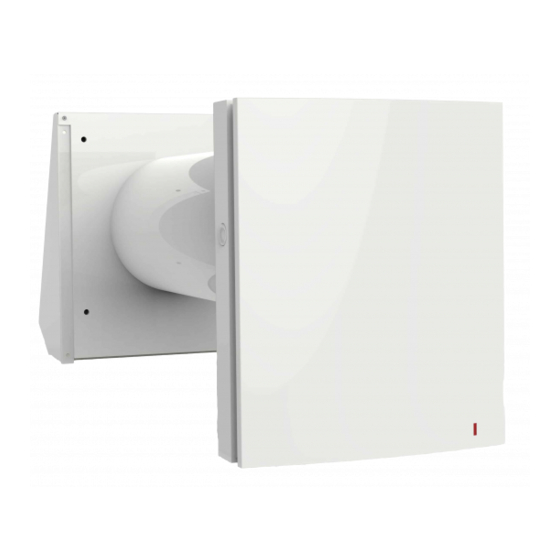
- Page 1 KERS 50 SINGLE-ROOM HEAT RECOVERY UNIT WITH REMOTE CONTROL USER & INSTALLATION MANUAL...
-
Page 2: Table Of Contents
KERS 50 – Heat recovery ventilation unit – User & installation manual READ THIS MANUAL CAREFULLY BEFORE USING THE UNIT INDEX index ................................2 INTRODUCTION ............................3 LIABILITY ..................................3 STANDARD OPERATIONAL RULES ............................ 4 OPERATIONS AND MAINTENANCE ........................... 4 USE .................................... -
Page 3: Introduction
KERS 50 – Heat recovery ventilation unit – User & installation manual 1. INTRODUCTION This manual indicates the intended use of the unit and provides instructions for transportation, installation, mounting, setting and use the unit. It provides information regarding maintenance, spare parts order, staff education and residual risks. -
Page 4: Standard Operational Rules
KERS 50 – Heat recovery ventilation unit – User & installation manual - Modifications made to the unit and to safety devices without prior written permission of the manufacturer; - Attempted repair on their own or by not authorized people ;... -
Page 5: Use
KERS 50 – Heat recovery ventilation unit – User & installation manual Make sure that safety devices are working properly and that you have doubts about how they work; otherwise not start in any case the unit; Use only tools specified from the manufacturer. To avoid injury, do not use tools worn or damaged, poor quality or improvised;... -
Page 6: Product Description
KERS 50 – Heat recovery ventilation unit – User & installation manual • Do not use flammable liquids for cleaning purposes. • Do not clean with oily products as the residue will cause to stick to the unit. • Do not clean with solvents will cause damage to paintwork •... -
Page 7: Operating Limits
KERS 50 – Heat recovery ventilation unit – User & installation manual Phase 1 - stale and hot air is extracted from the room. While flowing through the heat exchanger ceramic, heats it. So it moved up to 97% of the thermal energy. In 65 seconds the heat exchanger is heated and the unit switches to the second phase. -
Page 8: Wiring Diagram
KERS 50 – Heat recovery ventilation unit – User & installation manual 4.2 WIRING DIAGRAM CONNECTION OF A SINGLE UNIT The terminal block is protected by a transparent cover as shown in the figure. To access the terminal block see also section 7.2 of this manual. -
Page 9: On Board Switches And Remote Control
KERS 50 – Heat recovery ventilation unit – User & installation manual Place upstream a circuit breaker with a higher nominal current than the sum of that required by all the devices (see technical data table). When multiple KERS are connected in series, all are managed from the first one (master) and its on board switches or remote control. -
Page 10: Remote Control
KERS 50 – Heat recovery ventilation unit – User & installation manual The speed button is used to change the speed or to turn off the device. With repeated taps you pass, in sequence, from minimum speed, average speed, maximum speed, to the appliance is switched off. Three tiny LEDs next to the button will give feedback about which speed the unit is operating at. -
Page 11: Dip Switch Setting
KERS 50 – Heat recovery ventilation unit – User & installation manual Speed selection button: three buttons allow you to change the fan speed (and its flow). The button with the darker fan activates the highest speed, and vice versa. - Page 12 KERS 50 – Heat recovery ventilation unit – User & installation manual Air extraction This positioning of the switch enables extract operation of the ventilator in Ventilation mode. In heat recovery mode, the fan starts operating first in extract mode.
-
Page 13: Airtight Sealing Of The Unit
KERS 50 – Heat recovery ventilation unit – User & installation manual Dip-switch 6/7: Setting of delay in regulation based on the ambient humidity Posizione Description No delay The unit waits for 5 minutes before returning to the previously set speed... -
Page 14: Technical Data
KERS 50 – Heat recovery ventilation unit – User & installation manual 6. TECHNICAL DATA 6.1 MAIN TECHNICAL DATA KERS 50 heat Description recovery ventilation unit with remote control Codice Air flow at maximum speed mc/h Air exchange mc/h Heat recovery efficiency... -
Page 15: Energy Label Data
KERS 50 – Heat recovery ventilation unit – User & installation manual 6.2 ENERGY LABEL DATA Trade mark Ideal Clima Model VRKS50 Cold Average Warm Specific energy consumption (SEC), kWh/(m -86,5 -41,8 -16,0 Type of ventilation unit ------- Bidirectional --------... -
Page 16: After Sales & Maintenance
KERS 50 – Heat recovery ventilation unit – User & installation manual 7. AFTER SALES & MAINTENANCE 7.1 TROUBLESHOOTING On the following pages the most common reasons are reported that may cause the unit to stop or to operate incorrectly. The subdivision is made according to easily identifiable symptoms. - Page 17 KERS 50 – Heat recovery ventilation unit – User & installation manual Extract the body of the unit using the supplied string. Remove the filters from the body. Filters cleaning Clean the filters when needed, but in any case, not less than once in a year. An on-board LED turns on as a cleaning reminder.
-
Page 18: Disposal Of The Unit
KERS 50 – Heat recovery ventilation unit – User & installation manual Checking and cleaning of the outside hood The outside hood might become clogged over time because of leaves or other objects that will reduce the airflow and consequently the performance of the unit. Check that the external hood is free from obstructions at least twice a year and clean it according to need. -
Page 19: Exploded View Of The Components
KERS 50 – Heat recovery ventilation unit – User & installation manual 9.3 EXPLODED VIEW OF THE COMPONENTS Assembly drawing Central body 9.4 WALL MOUNTING Hole preparation Drill a hole through the wall with diameter min. 162 mm, inclined outwardly between 2° and 3°. - Page 20 KERS 50 – Heat recovery ventilation unit – User & installation manual Positioning installation template Place on the internal wall the cardboard template supplied with the unit and secure it temporarily (for example, with adhesive tape). Make sure the hole in the centre of the template is properly aligned with the plastic duct.
- Page 21 KERS 50 – Heat recovery ventilation unit – User & installation manual Front panel installation Press simultaneously the two hooks on the sides, lift the front of the indoor unit and remove the front plate Fix the rear part of the unit against the wall with the supplied screws. Open the transparent cover to connect the DC power cable to the terminals according to the wiring electric diagram.
-
Page 22: First Start-Up
KERS 50 – Heat recovery ventilation unit – User & installation manual Cable entry can take place as shown, both on the back side that the bottom side of the device. Insert the cartridge into the air duct as figured below. The pointer must be directed upwards. -
Page 23: Installation From Inside Through Flexible Grids
KERS 50 – Heat recovery ventilation unit – User & installation manual Make sure the wall socket is powered at 230 V. Insert the plug into the socket and, if there is, close the circuit breaker. Check that everything works. -
Page 24: Extension Duct For Thicker Walls
KERS 50 – Heat recovery ventilation unit – User & installation manual EXTENSION DUCT FOR THICKER WALLS In case the wall thickness is greater than maximum extensibility of the duct supplied with the unit, you can use the accessory telescopic extension duct Kers (code VPKT04), which increases the length by up to 80 cm. -
Page 25: International Warranty
KERS 50 – Heat recovery ventilation unit – User & installation manual INTERNATIONAL WARRANTY The warranty for this product is governed by the sale terms and conditions of Ideal Clima Srl (version 3.0) of which we quote the relevant part related to warranty: Ideal Clima guarantees its products for defects or manufacturing defects, with the express exclusion of any defect or done regarding the installation, operation and maintenance of the product. - Page 26 KERS 50 – Heat recovery ventilation unit – User & installation manual © Ideal Clima – Page 26 / 28...
- Page 27 KERS 50 – Heat recovery ventilation unit – User & installation manual © Ideal Clima – Page 27 / 28...
- Page 28 KERS 50 – Heat recovery ventilation unit – User & installation manual IDEAL CLIMA s.r.l. Via Magnolini 8 - 25135 BRESCIA – Italy Tel. +39.030.35.45.319 - Fax +39 030.51.09.329 info@idealclima.eu - www.idealclima.eu Version: 8.0 – Gennaio 2018 © Ideal Clima – Page 28 / 28...
Need help?
Do you have a question about the KERS 50 and is the answer not in the manual?
Questions and answers