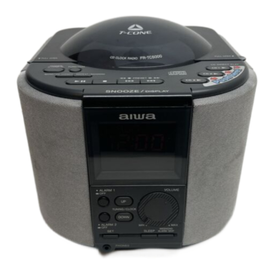
Aiwa FR-TC5000 Service Manual
Digital alarm cd clock radio
Hide thumbs
Also See for FR-TC5000:
- Operating instructions manual (48 pages) ,
- Service manual (43 pages)
Advertisement
Quick Links
All manuals and user guides at all-guides.com
FR-TC5000
K(S)
SERVICE MANUAL
CD CLOCK RADIO
BASIC CD MECHANISM: BZG-4 AB2NC1
This Service Manual is the "Revision Publishing" and replaces "Simple Manual"
(S/M Code No. 09-02A-454-9T2).
S/M Code No. 09-02A-454-9R2
Advertisement

Related Manuals for Aiwa FR-TC5000


Summary of Contents for Aiwa FR-TC5000
- Page 1 All manuals and user guides at all-guides.com FR-TC5000 K(S) SERVICE MANUAL CD CLOCK RADIO BASIC CD MECHANISM: BZG-4 AB2NC1 This Service Manual is the “Revision Publishing” and replaces “Simple Manual” (S/M Code No. 09-02A-454-9T2). S/M Code No. 09-02A-454-9R2...
- Page 2 All manuals and user guides at all-guides.com SPECIFICATIONS -1/1 Maximum outside dimensions (W × H × D) <Tuner section> 216 × 193 × 261 mm Frequency range FM: 87.5 – 108 MHz (50 kHz steps) (excluding projecting parts and MW: 531 – 1,602 kHz controls) (9 kHz steps) Weight...
- Page 3 All manuals and user guides at all-guides.com PROTECTION OF EYES FROM LASER BEAM DURING SERVICING -1/1 CAUTION This set employs laser. Therefore, be sure to follow carefully the instructions below when servicing. Use of controls or adjustments or performance of proce- dures other than those specified herin may result in WARNING!! hazardous radiation exposure.
- Page 4 Components marked X and R are not designated as spare parts for after sales service, and will not be stocked at the spare parts centers. UNIT-NAME ! C REF-NO PARTS-NO PARTS-NAME SUFFIX&MODEL FR-TC5000 O AS1001 8C-RD2-908-010 IB,(K) ! O AS1002 87-099-726-110 EURO CONVERTOR PLUG 250V/2.5A...
- Page 5 All manuals and user guides at all-guides.com SERVICE PRECAUTIONS -1/2 1. Disassembly Procedure 1. Remove 4 screws of a main part bottom. 2. Remove 2 screws of a inside CD lid (No-1 portion of Photo-1). 3. The speaker net left and right is removed, left and right each 2 screws are removed.
- Page 6 All manuals and user guides at all-guides.com SERVICE PRECAUTIONS -2/2 3. CD test mode functional explanation Operation Operation Contents MODE Display Test mode starting Start Mode FUNCTION All-points light APC circuit check All-points light All SERVO OFF Search Mode Leather current measurement LASER ON Focus error waveform check VCC ON...
- Page 7 Components marked X and R are not designated as spare parts for after sales service, and will not be stocked at the spare parts centers. UNIT-NAME ! C REF-NO PARTS-NO PARTS-NAME SUFFIX&MODEL FR-TC5000 0101 S1-101-001-0C0 CAP,E 100-10V 0102 S1-101-001-0C0 CAP,E 100-10V 0103 S5-102-120-500 C-CAP,0.001UF-50V 0104 S5-224-820-160 C-CAP,0.22UF-16V 0105 S5-103-120-250 C-CAP,0.01-25V...
- Page 8 Components marked X and R are not designated as spare parts for after sales service, and will not be stocked at the spare parts centers. UNIT-NAME ! C REF-NO PARTS-NO PARTS-NAME SUFFIX&MODEL FR-TC5000 0101 87-020-027-080 C-DIODE,1SS184 0221 87-020-027-080 C-DIODE,1SS184 0254 87-020-027-080 C-DIODE,1SS184 S IC 0101 87-A20-547-010 IC,CXA1992AR...
- Page 9 Components marked X and R are not designated as spare parts for after sales service, and will not be stocked at the spare parts centers. UNIT-NAME ! C REF-NO PARTS-NO PARTS-NAME SUFFIX&MODEL FR-TC5000 0152 S3-153-520-160 C-RES,15K-1/16W 0153 S3-102-520-160 C-RES,1K-1/16 0154 S3-123-520-160 C-RES,12K-1/16W 0156 S3-225-520-160 C-RES,2.2M-1/16W 0157 S3-225-520-160 C-RES,2.2M-1/16W...
- Page 10 Components marked X and R are not designated as spare parts for after sales service, and will not be stocked at the spare parts centers. UNIT-NAME ! C REF-NO PARTS-NO PARTS-NAME SUFFIX&MODEL FR-TC5000 FRONT 0303 S0-093-440-030 LED,L-934SECK FRONT 0304 S0-093-440-030 LED,L-934SECK FRONT 0305 011-010033-123 C-ZENER,3.3V 1/2W...
- Page 11 Components marked X and R are not designated as spare parts for after sales service, and will not be stocked at the spare parts centers. UNIT-NAME ! C REF-NO PARTS-NO PARTS-NAME SUFFIX&MODEL FR-TC5000 MAIN 0034 S0-010-005-0C0 CAP,E 1-50V MAIN 0035 S0-001-005-0C0 CAP,E 0.1-50V...
- Page 12 Components marked X and R are not designated as spare parts for after sales service, and will not be stocked at the spare parts centers. UNIT-NAME ! C REF-NO PARTS-NO PARTS-NAME SUFFIX&MODEL FR-TC5000 MAIN 0012 S0-041-480-000 DIODE,1N4148 MAIN 0013 S0-041-480-000 DIODE,1N4148...
- Page 13 Components marked X and R are not designated as spare parts for after sales service, and will not be stocked at the spare parts centers. UNIT-NAME ! C REF-NO PARTS-NO PARTS-NAME SUFFIX&MODEL FR-TC5000 MAIN 0036 S0-331-510-160 RES,330-1/16W (1 MAIN 0037 S0-100-510-160 RES,10-1/16W (1/...
- Page 14 All manuals and user guides at all-guides.com ELECTRICAL PARTS LIST -8/8 • Regarding connectors, they are not stocked as they are not the initial order items. The connectors are available after they are supplied from connector manufacturers upon the order is received. CHIP RESISTOR PART CODE Chip Resistor Part Coding Figure...
- Page 15 All manuals and user guides at all-guides.com BLOCK DIAGRAM -1/2 (TUNER & POWER AMP. SECTION) Q702 CN703 TRACKING TRACKING AM RF Q6,Q7 L9,TC1 L10,TC2 L11,D6 Q701 CN701 FM RF L1 , D2 POWER IC701 LC72131 FM OSC CN704 TA8227P L3 , D1 24 23 20 18 17 CN301...
- Page 16 All manuals and user guides at all-guides.com BLOCK DIAGRAM -2/2 (CD & CPU SECTION) CD SECTION CPU SECTION DISPLAY Q101 W181 CN303 CN101 LCD DRIVER IC301 74 67 39 38 37 36 LC877348A5Z52 IC161 IC101 24 17 CXD2589Q CXA1992AR 13 6 16 21 Q102 KEY MATRIX...
- Page 17 All manuals and user guides at all-guides.com SCHEMATIC DIAGRAM -1/3 (MAIN SECTION) L9,TC1 L10,TC2 MAIN C.B LW TRACKING MW TRACKING 2SC1815GR Q704 2SC1815GR 2SC1815GR MUTE SW Q702 2SC1815GR CD C.B W191 Q6,Q9 3V REG FRONT C.B CN702 SP701(L-CH) Q701 FM TRACKING 2SC1815GR JACK C.B Q703...
- Page 18 All manuals and user guides at all-guides.com WIRING -1/5 (MAIN C.B) MAIN C.B D805 C813 Q804 C814 JACK C.B CN705 C821 S301 (RESET) T801 CD C.B AC230V W191 50Hz FRONT C.B CN702 CN301 (MW-ANT.) (LW-ANT.) FRONT C.B CN302 (FM ANT.) CLOCK BATTERY BACKUP 006P-UE(6F22)9V-PP3 -18-...
- Page 19 All manuals and user guides at all-guides.com SCHEMATIC DIAGRAM -2/3 (CD SECTION) CD C.B C181 47/16 6.8k FRONT C.B PICK UP CN303 6.8k UNIT FFC101 JR100 JR101 10/16 10/16 SW C.B FFC201 TK/TKA 22/16 TK/TKA TK/TKA : CD SIGNAL MAIN C.B CN703 6.8k 6.8k...
- Page 20 All manuals and user guides at all-guides.com WIRING -2/5 (CD C.B) CD C.B LOADING MOTOR FFC101 FFC201 SW C.B PICK UP UNIT JR101 JR100 MAIN C.B CN703 FRONT C.B CN303 Q251 FFC251 MOTOR C.B -20-...
- Page 21 All manuals and user guides at all-guides.com WIRING -3/5 (MOTOR C.B/SW C.B) PICK UP UNIT FFC101 CD C.B CN101 MOTOR C.B SPINDLE LIMIT SW MOTOR SLED MOTOR FFC251 CD C.B CN251 SW C.B FFC201 CD C.B CN201 CLMP SW STKR1 SW STKR2 SW -21-...
- Page 22 All manuals and user guides at all-guides.com SCHEMATIC DIAGRAM -3/3 (FRONT SECTION) DOOR SW C.B KEY C.B (DOOR SW) TUNING/CLOCK DOWN POWER STANDBY/ON VOLUME FUNCTION PRESET CN351 CN351 (1-7) (1-7) ALARM 1 SLEEP BAND/FM STEREO MAIN C.B WEEKEND ALARM 2 SNOOZE/DISPLAY CN701 ALARM SKIP...
- Page 23 All manuals and user guides at all-guides.com WIRING -4/5 (FRONT C.B) FRONT C.B LCD301 KEY C.B CN351 MAIN C.B CD C.B CN301 W181 CN351 CN352 KEY C.B CN352 S308 S306 ALARM 1 C306 TUNING/CLOCK D305 S307 S305 ALARM 2 DOWN S302 S303 S304...
- Page 24 All manuals and user guides at all-guides.com WIRING -5/5 (KEY C.B/JACK C.B/DOOR SW C.B) DOOR SW C.B S321 CN304 (DOOR SW) Q303 KEY C.B S320 S319 POWER JACK C.B FUNCTION STANDBY/ON FRONT C.B FRONT C.B SP701 CN351 CN352 (L-CH) MAIN C.B CN704 SP702 (R-CH)
- Page 25 All manuals and user guides at all-guides.com VOLTAGE CHART -1/3 THE MEASURED VALUE IS DC VOLTAGE UNIT: V CD SECTION TEST CONDITION: CD PLAY IC301 (LC877348A5Z52) PIN'S NUMBER CD PLAY 4.87 4.92 4.81 0.05 0.58 4.86 PIN'S NUMBER CD PLAY 4.92 1.17 2.55...
- Page 26 All manuals and user guides at all-guides.com VOLTAGE CHART -2/3 IC251 (BA5936S) PIN’SNUMBER CD PLAY 3.57 3.56 3.50 3.58 2.53 2.53 7.60 7.63 PIN’SNUMBER CD PLAY 7.61 7.02 5.04 3.87 3.87 PIN’SNUMBER CDPLAY 3.43 3.60 3.22 2.53 7.62 2.53 PIN’SNUMBER CD PLAY 3.12 3.88...
- Page 27 All manuals and user guides at all-guides.com VOLTAGE CHART -3/3 TRANSISTORS Q101(A1362) Q102(C114) Q103(C114) 4.63 3.99 3.74 2.54 2.54 3.74 TRANSISTORS Q104(C114) Q105(C3326) Q106(C3326) 2.54 2.54 3.74 2.54 2.54 2.54 2.54 TRANSISTORS Q251(A1213Y) Q252(C124) Q253(C124) 5.04 TRANSISTORS Q254(A1235) Q255(A1235) Q256(C114) 3.87 -0.6 3.87...
- Page 28 All manuals and user guides at all-guides.com ADJUSTMENT -1/1 MAIN C.B IFT1 Test point 1 16pin Test point 2 1. AM IF Adjustment 5. FM Tracking Adjustment Testpoint: IC1 (TA2104AN) 16PIN (TP1) Testpoint: IC1 (TA2104AN) 16PIN (TP1) Adjustment location: IFT1 Adjustmentlocation: L1 IFT1 ................
- Page 29 All manuals and user guides at all-guides.com LCD DISPLAY -1/1 (N-04D-32) SEGMENT COMMON -29-...
- Page 30 All manuals and user guides at all-guides.com IC BLOCK DIAGRAM -1/3 IC, BA5936S Rog CURRENT DETECTOR TERMINAL IC, LC72131D REFERENCE PHASE DETECTOR DIVIDER CHARGE PUMP SWALLOW COUNTER UNLOCK 1/16,1/17 4bits DETECTOR 12bits PROGRAMMABLE DIVIDER DATA SHIFT REGISTER UNIVERSAL LATCH COUNTER POWER RESET -30-...
- Page 31 All manuals and user guides at all-guides.com IC BLOCK DIAGRAM -2/3 IC, CXA1992AR RF SUMMING AMP PD2 IV PD1 IV FE_BIAS SENS2 ↓ SENS1 LASER POWER CONTROL F IV AMP FE AMP C. OUT E IV AMP DFCT XRST LEVEL S FO.
- Page 32 All manuals and user guides at all-guides.com IC BLOCK DIAGRAM -3/3 IC, CXD2589Q 25 26 27 28 TES1 TEST Clock Error XRST Corrector Generator RMUT Interface demodurator Serial-In LMUT Interface ASYI Asymmetry ASYO XTAI Timing Corrector BIAS Logic XTAO Over Sampling Digital Filter XPCK 3rd-Order...
- Page 33 All manuals and user guides at all-guides.com IC DESCRIPTION -1/1 (LC877348A5Z52)-1/2 Pin No. Pin Name Description LD-MOT-FWD CD mechanic changer control output motor control LD-MOT-REV CD mechanic changer control output motor control CLOCK CD control serial port XLAT CD control serial port DATA CD control serial port SENS...
- Page 34 All manuals and user guides at all-guides.com IC DESCRIPTION -1/1 (LC877348A5Z52)-2/2 Pin No. Pin Name Description ALARM1 KEY ALARM1 button input terminal (Lo active) ALARM2 KEY ALARM2 button input terminal (Lo active) UP KEY UP button input terminal (Lo active) DOWN KEY DOWN button input terminal (Lo active) SET KEY...
- Page 35 All manuals and user guides at all-guides.com MECHANICAL EXPLODED VIEW -1/1 -35-...
- Page 36 Components marked X and R are not designated as spare parts for after sales service, and will not be stocked at the spare parts centers. UNIT-NAME ! C REF-NO PARTS-NO PARTS-NAME SUFFIX&MODEL FR-TC5000 O MC1001 8C-RD2-011-010 WINDOW,FR O MC1002 8C-RD2-012-010 KNOB,VOL...
- Page 37 All manuals and user guides at all-guides.com COLOR NAME TABLE -1/1 Basic color symbol Color Basic color symbol Color Basic color symbol Color Black Cream Orange Green Gray Blue Transparent Blue Gold Pink Silver Titan Silver Brown Violet White Transparent White Yellow Transparent Yellow Metallic Blue...
- Page 38 All manuals and user guides at all-guides.com CD MECHANISM EXPLODED VIEW -1/2 <BZG-4 AB2NC1> -38-...
- Page 39 All manuals and user guides at all-guides.com CD MECHANISM PARTS LIST -1/2 <BZG-4 AB2NC1> = ! SAFTY PARTS = Components marked All components used on this model at the production line are shown in this service manual. However, please note that not all components will be available as spare parts for after-sales service. Components marked S and O are designated as spare parts for service and will be stocked at the spare parts centers.
- Page 40 All manuals and user guides at all-guides.com CD MECHANISM EXPLODED VIEW -2/2 <BZG-D YB1NF> -40-...
- Page 41 All manuals and user guides at all-guides.com CD MECHANISM PARTS LIST -2/2 <BZG-D YB1NF> = ! SAFTY PARTS = Components marked All components used on this model at the production line are shown in this service manual. However, please note that not all components will be available as spare parts for after-sales service. Components marked S and O are designated as spare parts for service and will be stocked at the spare parts centers.
- Page 42 Components marked X and R are not designated as spare parts for after sales service, and will not be stocked at the spare parts centers. UNIT-NAME ! C REF-NO PARTS-NO PARTS-NAME SUFFIX&MODEL FR-TC5000 S0-019-000-000 EYELET S0-001-000-000 CABLE/PLASTIC TIE SC-RD2-970-000 POLYTHENE FOAM CUSHION S:55x5 8C-RD2-043-010 AC CORD CAUTION LABEL CRD2-94 87-057-961-010 CAUTION LABEL 87-056-864-010 DIFFERENCE LABEL <K>...
Need help?
Do you have a question about the FR-TC5000 and is the answer not in the manual?
Questions and answers