
Related Manuals for AMI The Barracuda 4010LX

Summary of Contents for AMI The Barracuda 4010LX
- Page 1 THE BARRACUDA MODEL 4010L TUNABLE DIODE LASER ABSORPTION SPECTROMETER Operator Manual...
-
Page 2: Table Of Contents
Note: Read this manual carefully prior to installation. Please take extra precautions against any potential leaks when installing and operating your BARRACUDA MODEL 4010LX. If you have any questions, contact AMI at 714.848.5533 or www.amio2.com. TABLE OF CONTENTS MODEL 4010LX Overview ___________________________________________________ 2... -
Page 3: Model 4010Lx Overview
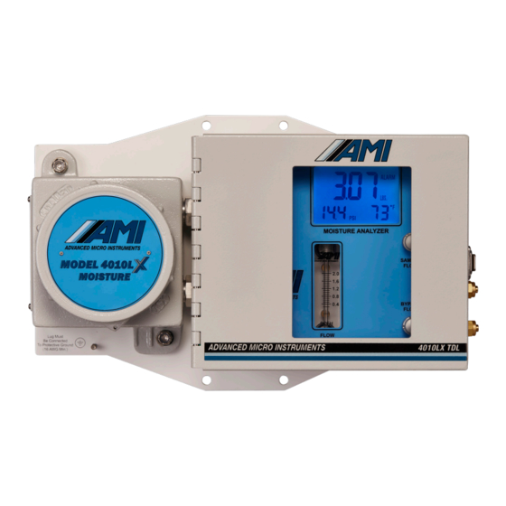
ANALYZER OVERVIEW Mounting Plate Mounting Hole (x 4) Explosion-proof Enclosure Up and Down Arrow Buttons Exhaust Port Sample Gas Inlet Port Bypass Gas/Liquid Drain Sample Gas Metering Valve ½" NPT Machined Bypass Flow Holes for Electrical Metering Valve (front view) Connnections (x 2) (not shown in image) Flow Meter... -
Page 4: Method Of Measurement
Over longer periods of time, the laser wavelength can drift. A standard feature of the MODEL 4010LX Moisture Analyzer is that it tracks the original location of the background methane absorption. Using AMI’s Software , the customers can easily check for COMMAND CENTER any drift in the laser wavelength and, if necessary, correct it with a simple click of a button. - Page 5 MODEL 4010LX using their own NIST traceable calibration gas, but it is important to follow AMI's specific steps so that errors are not introduced. You can read AMI’s recommendations for field validation of a MODEL 4010LX...
-
Page 6: Key Innovations
KEY INNOVATIONS Advanced Micro Instruments has developed and patented key technologies that enable our devices to deliver the highest levels of PERFORMANCE, RELIABILITY and EASE-OF-USE. These technologies are included in THE BARRACUDA MODEL 4010LX and cannot be replicated by any other company. ELIMINATOR CELL BLOCK Our patented Cell Block Technology provides the next generation of innovation for a complete, very compact sample system that virtually eliminates all... -
Page 7: Safety, Warnings & Cautions
SYMBOL TABLE WARNING - RISK OF DANGER OR HARM RISK OF SHOCK (DC) TO THE USER or RISK OF DAMAGE TO THE PRODUCT. Consult the operator manual. Relay RISK OF SHOCK (AC) Earth Ground Protective Ground DC (Direct Current) AC (Alternating Current) Frame Chasis Terminal SAFETY, WARNINGS &... - Page 8 WARNING You must follow the National Electrical Code (NEC) in your installation. Consult the NEC Handbook for the correct guidelines and standards. Class I, Div 1 areas must use rigid conduit with seal-offs. Class I, Div. 2 areas can use flexible conduit with seal-offs. The Analyzer has approval for Class I, Division 1, Groups B,C,D.
- Page 9 The voltage rating of the AC Analyzer is 100 to 240VAC at 50/60Hz ± 10%. •Any AC voltages outside this range may cause the Analyzer to malfunction Any use of this equipment in a manner not specified in this manual or approved AMI documentation may impair the protection provided by the equipment.
-
Page 10: Analyzer Installation
ANALYZER INSTALLATION Part I: Mounting the Analyzer note: Analyzer weighs 17.0 lbs (7.7 kg) Key Points • The Analyzer can be mounted either indoors or outdoors, where the ambient temperature remains between 20°F (-6.7°C) and 149°F (65°C) • When using a solar panel to power the Analyzer, we recommend mounting the solar panel just above the Analyzer, using the same mast, to serve as a sunshield WARNING: For both DC and AC models, do not use above 3,200 m (10,500 ft). -
Page 11: Part Ii: Electrical Connections For The Analyzer
Part II: Electrical Connections for the Analyzer Key Points: • Verify your rated power supply matches the operating voltage of your Analyzer before you begin THE MODEL 4010LX is available with either AC or DC Power (you must request your •... - Page 12 Right Conduit Union Left Conduit Union Electrical Seal-offs Install the conduit unions between the explosion-proof housing of the Analyzer and the electrical seal-off. DO NOT fill the electrical seal-offs yet. • In order to meet electrical codes for Class 1, Div 1 and Class 1, Div 2, Groups B,C,D, you must use electrical seal-offs in your installation •...
- Page 13 Terminal Cover Terminal Cover DC Version with Terminal Cover AC Version with Terminal Cover and white information panel and black information panel Remove the explosion-proof cover by rotating it counterclockwise. Note: A white sheet metal panel inside the explosion-proof housing indicates the Analyzer has been built for use with DC power, while a black sheet metal panel indicates AC power.
- Page 14 • If you decide to use a 2-wire cable with shield for • N is for the Neutral Wire the power supply connection, AMI provides quality Shield Earth Ground Terminal Connection • Position (A), as shown above, is for the AC Power...
- Page 15 RECOMMENDED: WHEN USING DC POWER, USE A SHIELDED-TWISTED PAIR CABLE AND CONNECT THE CABLE SHIELD TO THE SHIELD EARTH GROUND TERMINAL SHOWN IN POSITION 'A' OF THE ILLUSTRATION ABOVE. DO NOT CONNECT THE OTHER END OF THE SHIELD WIRE AS IT WILL CAUSE UNDESIRABLE GROUND LOOPS! (DC Power Version is shown for alarm wiring.
- Page 16 2nd CONDUIT (ANALOG OUTPUTS & RS485 COMMUNICATION): (DC Power Version is shown. Instructions are the same for the AC Power Version) Analog Output should be connected using a twisted 2-conductor wire with shield NOTE: Always use a twisted 2-conductor cable with shield. Never connect both ends of the shield to both devices (Analyzer and other device) as it will cause ground loops.
-
Page 17: Part Iii: Gas Connections
Part III: Gas Connections Key Points: • All gas connections will require using the supplied ferrule set, ¼" stainless steel compression fittings and customer-supplied ¼" stainless steel tubing • Sample Gas Inlet Pressure to the Analyzer should be regulated down to the range of 1.0 to 20.0 psig (0.07–1.4 bar), depending on line pressure •... - Page 18 STEPS has 3 gas connections on its right side. THE BARRACUDA MODEL 4010LX Exhaust Port Sample Gas Inlet Port Bypass Gas/Liquid Drain Sample Gas Connection Take a deburred length of ¼" stainless steel tubing and slip it through the supplied compression nut and ferrule set.
- Page 19 Exhaust Gas Connection Take another deburred length of ¼" stainless steel tubing and slip it through the supplied compression nut and ferrule set. Confirm that the ferrule set is properly oriented and then connect to the EXHAUST PORT. Make sure the ¼ stainless steel tubing slips all the way into the compression fitting until it bottoms out.
-
Page 20: Initiation Of Sample Flow
Note: AMI has chosen this technique since all bypass flow meters have a tendency to plug quickly due to the volume of liquids and particulates going through the bypass path. END OF INSTALLATION... -
Page 21: Calibration
CALIBRATION Unlike most gas sensing technologies, The MODEL 4010LX moisture analyzer does not require periodic calibrations. By design, there is no required method for field-calibrating a 4010LX. Wavelength-modulat- ed tunable diode laser (WMTDL) spectroscopy-based instruments, like the 4010LX, are extremely stable and reliable. - Page 22 How to set the Alarms on THE BARRACUDA MODEL 4010LX? Alarm Two Alarm One Up and Down Adjust Buttons THE BARRACUDA MODEL 4010LX comes standard with two fully, adjustable independent alarms (ALARM ONE and ALARM TWO) that can be adjusted over THE BARRACUDA's entire moisture measurement range.
-
Page 23: Command Center Interface Software Set-Up
To access the more sophisticated features available on MODEL 4010LX requires installing the current COMMAND CENTER Software version of the SET-UP COMMAND CENTER SOFTWARE Step 1: Remove the explosion-proof cover to access the USB Port (Type B) of the Analyzer USB Port (Type B) (DC Power Version is shown. - Page 24 COMMAND CENTER Software window shown with settings for MODEL 4010LX Above: Once the link is established, the software will automatically recognize the Analyzer and populate the Analyzer Info Column with information specific to your Analyzer. View of the Left Status Column of the User Interface The Analyzer Info Column will display the following information about your Analyzer: •...
-
Page 25: Analyzer Output Setup
Step 3: Selection of Options in Analyzer Setup Area & Syncing with EFM Set your desired SECURITY SETTINGS. You have 2 options available to select from: –NONE allows anyone to make changes to the Analyzer's settings using the front panel –FULL prevents anyone from changing the Analyzer's settings using the front panel. - Page 26 Sync your EFM (electronic flow meter) or similar device to your Analyzer. The following steps are critical because they will ensure that both devices display the same measurement readings and, thereby, prevent unnecessary confusion in the future. 1. By now, you have already wired your EFM or similar device to the Analyzer using the Analyzer's analog output terminals.
- Page 27 CHANGING ANALOG OUTPUTS (OPTIONAL) Changing your ANALOG OUTPUT from 4–20mA to 1–5 VDC or vice versa. (Skip this step if you DO NOT want to change your ANALOG OUTPUT.) Click on the drop down menu of ANALOG OUTPUT and select the output option that you wish to change to. IMPORTANT Whenever you change the ANALOG OUTPUT from 4–20mA to1–5 VDC or vice versa, you will need to complete the following steps to verify your ANALOG OUTPUT.
-
Page 28: Alarm Setup
Step 4: Alarm Logic & Setup The Analyzer features 2 independent Moisture Concentration Alarms – one for ALARM 1 and one for ALARM 2. The settings for these alarms, including setpoints, relay contacts, close/open logic and alarm delays, COMMAND CENTER. are adjusted through the It is important that you plan out how you want your ALARM LOGIC to work for each ALARM before you start adjusting the settings discussed in... - Page 29 c) Click on the drop-down menu and set the ALARM to trigger ABOVE SETPOINT or BELOW SETPOINT. This causes the alarm flag located on the LCD to illuminate in accordance with your desired setting and the alarm relay contact to open or close as configured in the next step.
-
Page 30: Controls Both Alarms Setup
Step 5: Setup of the Controls for Both Alarms IMPORTANT: For this section, the adjustments discussed below will affect both ALARMS and CANNOT be set independently for each ALARM. a) Set the ALARM BYPASS. Use the UP and DOWN ARROWS to set the duration of your ALARM BYPASS (HOLDOFF). -
Page 31: Datalog Column Setup
CAUTION: DO NOT adjust this setting unless you are using a pulse-latch slam valve! Otherwise, you will override the relay logic for your Alarms. d) This feature is provided for powering a Pulse Latched Slam Valve. The valve manufacturer should indicate the time, in seconds, for the valve to Open or Close. -
Page 32: Download Data
DOWNLOAD DATA Software. To begin, click the DOWNLOAD DATA Button located on the COMMAND CENTER A DATALOG HANDLER window will appear, giving you the options of seeing your downloaded data as either a graph or spreadsheet. - Page 33 To see the graph, click the GRAPH Button. (Sample Graph of Downloaded Data) You can save your graph to a file by clicking the SAVE DATA Button.
- Page 34 To see your downloaded data as a spreadsheet instead, click the SPREADSHEET Button. on the DATALOG HANDLER Window. (Sample Spreadsheet of Downloaded Data) You can save your spreadsheet to a file by clicking the SAVE DATA Button. END OF DATA DOWNLOAD...
-
Page 35: Troubleshooting, Maintenance & Repairs
MAINTENANCE, TROUBLE SHOOTING & REPAIRS Viewing the Moisture Readings To view the waveform of your measurement readings, click the LASER ANALYSIS Button located on the bottom of the Operational Status Column of the COMMAND CENTER. A separate Laser Graph Window will appear and display the waveform of the current moisture measurement. - Page 36 Sample Waveform Displayed in the Laser Graph Window Laser Power Waveform Moisture Peak Peak Absorption Waveform The graph above shows a typical waveform that a user should see when THE BARRACUDA is measuring the concentration of H₂O in a sample. •...
- Page 37 The following section identifies potential system issues and provides possible resolutions. The waveforms on the graph of each moisture measurement can indicate whether an issue needs to be addressed. If you are unable to resolve an issue after following the suggestion shown in this section, contact AMI for further support.
- Page 38 Resolution: First, check to verify that the laser power is present. The blue waveform represents the laser power of THE BARRACUDA MODEL 4010LX. If its pattern appears, as shown above, it means that the laser is func- tioning properly. Then check your Sample Inlet from the pipeline to THE BARRACUDA, making sure that all connections are secured and have no leaks.
-
Page 39: Cleaning The Mirrors
Cleaning the Mirrors Note: AMI has taken many precautions for keeping the critical laser path clean during use in harsh gas pipeline conditions. Our compact patented cellblock/sample system incorporates unique features; including a membrane that blocks liquids and particulates found in the gas stream and bypassing them prior to reaching the critical Herriott Measurement Cell. - Page 40 Safety, Warnings and Cautions This procedure describes the method for field servicing and cleaning of the MODEL 4010LX's Herriot cell mirrors. WARNING All power must be turned off and disconnected from the Analyzer before performing the mirror cleaning procedure. WARNING The Herriot cell mirrors are a key component of our precision optics.
- Page 41 Philips Screws (2x) Connector Cover Remove the two Philips screws and connector cover to access the electrical connections. Mains Power Supply Disconnect mains power supply from analyzer by removing the green Phoenix connector from the terminal strip. Far Mirror Disassembly and Inspection — Detector End Far Side End Cap The Far Mirror –...
- Page 42 Screw Screw Open the enclosure door. Remove both flow control knobs by loosening the 2 set screws with 1/16” Hex wrench until the knobs slip off the valve stem. Philips Screws (4x) Remove the (4) Philips screws holding the front panel. Lift the front panel carefully off of the analyzer while monitoring the internal cabling.
- Page 43 Name Plate Remove the nameplate by removing the 4 x panhead screws with a 5/64” hex wrench. Detector Cable Disconnect the detector cable from the detector PCB. Tuck away the cable so it is out of the way. Socket Head Cap Screw Bracket WARNING Be careful not to damage dowel pins of Herriot cell when...
- Page 44 Herriott cell block. If there is significant contamination on the Herriott cell walls (image above), the analyzer will need to be sent back to the AMI factory for service. Re-assemble the analyzer prior to return to AMI.
- Page 45 Near Mirror Disassembly and Inspection — Laser End Near Side End Cap Head Cap Screw Remove the white fiber optic loop hanger by unscrewing the 6-32 nut and carefully removing the hanger from the left side of the case.
- Page 46 Cap Screw Fiber Optic Strain Relief Tube Remove the (4) socket head cap screws holding the far end cap in place with a miniature rachet and 7/64 hex wrench. Start by loosening all 4 cap screws ¼ turn before completely removing any of the screws.
- Page 47 Optical Wipe Fiber Optic Laser Hoop Set end cap on top of the case, with an optical wipe underneath it and do not damage this yellow fiber optic laser hoop during the cleaning process. CAUTION The Herriot cell mirrors are precision optics. Any damage to the surface of the mirrors can result in degradation of analyzer performance.
- Page 48 Remove and discard o-rings from removed endcaps. Using the AMI supplied optical wipes and 99% pure isopropyl alcohol, apply a few drops onto the wipe and then lightly rub one of the mirrors surfaces. Use light pressure only and small circular motion.
- Page 49 Reinstall the far end mirror assembly (right detector end) by carefully aligning the dowel pins with the end cap and slip into place. Slip screws into place and tighten in a star pattern. Reattach white detector connector. Replace the side cover and screws. Reattach front panel by carefully reconnecting the 3 cables and then front panel screws.
- Page 50 Error Status Display: Error Reference Guide The following section shows the existing error(s) that can be detected by the Analyzer and displayed on the Error Status Display. Each error has an assigned number and message. Note: Once troubleshooting is completed and the error is resolved, the message will automatically be removed from the Error Status Display by the Analyzer.
- Page 51 IMPORTANT MESSAGE ABOUT CLEANING REQUIREMENTS The Analyzer is designed to function properly without cleaning requirements. at 714.848.5533 or visit For any other issue not covered in this section, contact AMI us at www.amio2.com for support. END OF MAINTENANCE, TROUBLESHOOTING & REPAIRS...
-
Page 52: Smart Realignment
SMART REALIGNMENT Using to Realign the Signature Peaks SMART REALIGNMENT If your signature peaks have shifted, the ERROR STATUS DISPLAY will automatically display the error messages, alerting you to the need to realign your peaks. STEP 1: To begin, click on the LASER ANALYSIS Button at the bottom on the Operational Status Column. A new window will appear and display the current measurement waveform. - Page 53 STEP 2: Type in the correct password that you received from an AMI phone call in the password entry area. The display window will slightly change. STEP 3: Click on the TIP of the misaligned methane signature peak. Note: This peak is in the left area of the waveform and separated from the signature weak peak by 3 non-designated peaks.
- Page 54 STEP 4: Click on ADJUST PEAKS on the upper right-hand corner of the screen. The display will slightly change again. While the realignment process is taking place, you will see the screen displaying ADJUSTING WAVEFORM and an adjacent 'working bar' in the upper right-hand corner, highlighted by the red box. When the process is nearing completion, the screen will adjust once more and display DOWNLOADING WAVEFORM.
- Page 55 Once everything is done, a new waveform will appear, displaying the fully adjusted signature methane peak and water peak. The Red Error Message will also disappear and be replaced with ERROR: NONE. SMART REALIGNMENT. At this point, you can close the You have now successfully completed COMMAND CENTER Window.
- Page 56 STEP 2: Type in the correct password that you received from AMI in the password entry area. The display window will slightly change. STEP 3: Click on the TIP of the misaligned methane signature peak. Note: This peak is in the left area of the waveform and separated from the signature weak peak by 3 non-designated peaks.
-
Page 57: Modbus Rs485 Communication Protocol
• Go to the User Input of the Variable Page. Click on the USER INPUT and enter 'AMI' for the password when prompted. Then, return to the USER INPUT • In the USER INPUT, enter the following to change the address of the Modbus: A0WN1<Address>, where <Address>... - Page 58 Table I: Holding Registers for BARRACUDA MODEL 4010LX Register Number of Variable Description Type Comment Register Name Used A0RA0 Reading String String A0RZ2 PPM Value Two 16-bit Unsigned v7.0 Firmware Integers or Above A0RZ3 LBS x 100 Value 16-bit Unsigned Integer v7.0 Firmware or Above A0RA1 2F Baseline...
- Page 59 Table I: Holding Registers for BARRACUDA MODEL 4010LX (continued) Register Number of Variable Description Type Comment Register Name Used A0RJ0 Analyzer Type String A0RJ1 Analyzer Configuration 16-bit Unsigned Integer A0RL0 Analyzer Serial Number String A0RL1 Analyzer Tracking Number String A0RL2 Analyzer User ID String A0RL3...
-
Page 60: Specifications
SPECIFICATIONS USAGE Both indoor and outdoor use Altitude for Use _______________________________________ <3,200 meters (10,500 ft) for DC and AC models Relative Humidity___________________________________________________________ <95%, non-condensing Ingress Protection__________________________________________________________________________IP65 PHYSICAL Dimensions _________________________________________ 14.0”W x 9.5”H x 5.0”D (36 cm x 24 cm x 13 cm) Weight _______________________________________________________________________ 17.0 lbs (7.7 kg) Digital Display ____________________________________________________________________ 4–digit LCD Mounting _______________________________________________________________ Wall mount or 2.0"... - Page 61 AREA CLASSIFICATION Area Classification ___________________________ US/Canada: Class I, Division 1, Groups B-D, T4 Class I Zone 0/1, AEx ia op is/db IIB+H2 T4 Ga/Gb Ex ia op is/db IIB+H2 T4 Ga/Gb -20°C ≤ Tamb ≤ +65°C IECEX: Ex ia op is/db IIB+H2 T4 Ga/Gb -20°C ≤...
-
Page 62: Ami ® Warranty & Support
DURATION TO TWO (2) YEARS FROM THE DATE OF SHIPPING. LIMITATION OF LIABILITY IN NO EVENT WILL AMI BE LIABLE TO YOU FOR ANY SPECIAL DAMAGES, INCLUDING ANY LOST PROFITS, LOST SAVINGS, OR OTHER INCIDENTAL OR CONSEQUENTIAL DAMAGES, EVEN IF THE COMPANY HAS BEEN ADVISED OF THE POSSIBILITY OF SUCH DAMAGES, OR FOR ANY CLAIM BY ANY OTHER PARTY. - Page 63 THIS PAGE LEFT INTENTIONALLY BLANK...
- Page 64 HIGH PERFORMANCE RELIABILITY INTUITIVE DESIGN ADDRESS: www.amio2.com Advanced Micro Instruments, Inc. ® 714.848.5533 225 Paularino Avenue 714.848.4545 Costa Mesa, CA 92626 OM-300-039 Rev A 09/14/2021 © Advanced Micro Instruments, Inc.
Need help?
Do you have a question about the The Barracuda 4010LX and is the answer not in the manual?
Questions and answers