Table of Contents
Advertisement
Quick Links
Advertisement
Table of Contents

Related Manuals for PVA MR2


Summary of Contents for PVA MR2
- Page 1 WHERE PRECISION DRIVES PRODUCTION Owner’s Manual Revision B...
- Page 2 MR2 Manual This document is based on information available at the time of its publication. While efforts have been made to ensure the contents of this manual are accurate, the information contained herein does not purport to cover all specific details or variations in hardware, or to provide for every possible contingency in connection with installation, operation, or maintenance.
-
Page 3: Table Of Contents
Bottom Fluid Section ............................ 15 Metering Piston Assembly ........................... 18 Metering Sleeve ............................. 19 Fill the Fluid Distribution Block ........................25 Install the MR2 ............................... 26 Maintenance ..........................27 Spare Parts ..........................27 Technical Specifications ......................28 Troubleshooting ........................28 Damaged Valve Gasket ............................ -
Page 4: Introduction
Before you operate this system, read the operation and setup manual. This will help you to become familiar with the product and ensure successful operation. If any questions or problems arise, contact PVA’s Technical Support department. PVA Contact Information Main Office... -
Page 5: Safety
MR2 Manual Safety Certain warning symbols are affixed to the machine and correspond to notations in this manual. Before operating the system, identify these warning labels and read the notices described below. Not all labels may be used on any specific system. - Page 6 MR2 Manual Do not smoke near the PVA UV cure machine. Always have a fire extinguisher available for emergency use. Before performing any repairs or maintenance to the system, turn off power and lock out the power disconnect switch. Warning notices are used to emphasize that hazardous voltages, current, temperatures, or other conditions that could cause personal injury exist in this equipment or may be associated with its use.
-
Page 7: Theory Of Operation
MR2 Manual Theory of Operation The MR2 has a dual piston system and can process 2K materials with mix ratios up to 15:1. For 1K chemistries, the MR2 alternates metering chambers to reduce refill time and increase throughput. Each metering chamber is controlled independently so the mix ratio and flow rate can be changed at the application point. -
Page 8: Setup
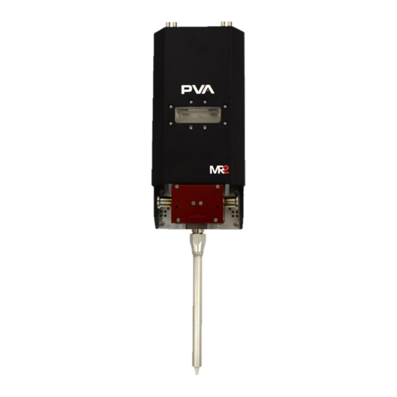
MR2 Manual Setup Before you operate the MR2 Metered Piston Dispenser, read and understand this manual. This information is for safety and correct operation of the valve. This manual provides the information needed to operate, repair, and troubleshoot. Overview The MR2 Metered Piston Dispenser is constructed from three main components. -
Page 9: Operation
Note: Use only compatible solvents and materials or the seals and O-rings will be damaged. Bleed the Pump To bleed the MR2, dispense all the way until the rods reach their full travel. Repeat this five times to get all air out of the system. Shutdown Refer to the workcell manual for information on how to shut down the workcell. - Page 10 MR2 Manual 6. Remove any lubrication fluid in the fluid distribution block. 7. Examine the oil window gasket for any signs of wear or damage. Replace the gasket if there are signs of wear. 8. Use a 3 mm hex key to remove the six M4x16 bolts on the front of the air body.
- Page 11 MR2 Manual 14. The valve gasket is the black mat under the air body. Remove the valve gasket and clean it. 15. Examine the valve gasket for any cracks or signs of wear on the side that was facing the metering sleeve. If the valve gasket is worn, it will be necessary to replace. DO NOT flip the valve gasket over or you can damage the valve.
- Page 12 MR2 Manual 19. Loosen the six M4x55 screws and separate the metering sleeve from the metering body. Figure 11: Remove the Metering Sleeve Screws 20. Separate the metering sleeve from the metering body. Figure 12: Separate the Metering Sleeve from the Metering Body 21.
- Page 13 MR2 Manual Figure 14: Rod/Cylinder Assembly Removed 22. Remove both rod/cylinder assemblies. 23. Remove the piston rods from the carbide cylinders. 24. Remove and examine the two O-rings on the top and bottom of the carbide cylinders for any sign of wear or damage. If they are damaged, replace them.
- Page 14 MR2 Manual 27. There are two ways to remove the washer/lip seal assembly from the piston. You can use a vice or soft jaw pliers. • Use soft jaw pliers to hold the piston, use a screwdriver with the other hand to loosen the piston lip screw.
-
Page 15: Assembly Instructions
MR2 Manual 30. Use 90° pliers to take off the 5/8” snap ring that holds the piston bushing in place. Figure 20: Remove the Snap Ring 31. Examine the two internal O-rings for any signs of damage or wear. Assembly Instructions Bottom Fluid Section 1. - Page 16 MR2 Manual Figure 23: Pistons Installed 5. Install the valve stop. It should slide over the pins for correct alignment and the pistons should be flush with the top of the valve stop. Figure 24: Install the Valve Stop 6. Install the valve gasket over the dowel pins on top of the valve stop.
- Page 17 MR2 Manual 7. Install the fluid distribution block. The pins in the valve body will align the sections. Figure 26: Fluid Distribution Block Note: Make sure the fluid distribution block is installed so the fluid outlet is on the same side as the etched part number on the valve stop.
-
Page 18: Metering Piston Assembly
MR2 Manual Metering Piston Assembly 1. Apply silicon grease to the O-ring side of the lip seal. Figure 29: Apply Grease to the Lip Seal 2. On the threaded end of the piston, install the piston lip, the lip seal, and the screw. -
Page 19: Metering Sleeve
MR2 Manual Metering Sleeve 1. Apply grease to four Kalrez® O-rings and install one in each end of the metering sleeves. Figure 32: Metering Sleeve with O-rings Installed 2. Install the metering sleeve into the metering body. Figure 33: Install the Metering Sleeve Note: When correctly installed, the bottom of the cylinders will sit flush with the bottom of the metering sleeve. - Page 20 MR2 Manual 4. Install the bushing into the top of the metering body. Figure 35: Install the Bushing 5. Use 90˚ snap ring pliers to install the 5/8” snap ring on the end of the bushing to hold it in place.
- Page 21 MR2 Manual Figure 38: Apply Grease 8. Install the oil window. Use a 2.5 mm hex key to install the eight M4x12 button head screws into the oil window. Tighten to (15) inch-pounds. Do not overtighten the screws or you will crack the window.
- Page 22 MR2 Manual 10. Make sure the rods continue through to the bushings. Figure 41: Rods Engage Through the Bushing Figure 42: Rods Installed Through the Bushings 11. Use the pins in the metering sleeve to align it with the bottom of the metering body.
- Page 23 MR2 Manual 12. Install the six M4x55 screws and use a 3 mm hex key to tighten them. Figure 44: Install and Tighten Screws 13. Apply a small amount of grease to the two metering sleeve O-rings and install them.
- Page 24 MR2 Manual Figure 47: Clamp Adapter Seal 17. Install the clamp elbow. Figure 48: Clamp Elbow Installed 18. Install the clamp. Turn the wing screw until it is tight. Figure 49: Install the Clamp Page 24 of 34 Revision B...
-
Page 25: Fill The Fluid Distribution Block
MR2 Manual 19. Install the clamp adapter seal. Figure 50: Clamp Adapter Seal 20. Install the clamp adapter. 21. Install the clamp. Turn the wing screw until it is tight. 22. Install any air or material ports. 23. Install the mixer nut. -
Page 26: Install The Mr2
1. Install the four screws to attach the MR2 onto the assembly. 2. Install the cover and install the cover screws. Figure 54: MR2 with Cover 3. Install the MR2 onto the work station or in the workcell as necessary. Page 26 of 34 Revision B... -
Page 27: Maintenance
O-ring, -014, Buna VLV-014B O-ring, -021, Kalrez VLV-021K O-ring, -024, Buna VLV-024B O-ring, -040, Buna VLV-040B Figure 56: B82-MR2 Spare Parts List Contact PVA for information on replacement parts or to order. Page 27 of 34 Revision B June 2021... -
Page 28: Technical Specifications
Bell Style (for 1K applications, we have a 1/4” NPT option) Figure 57: Technical Specifications Troubleshooting This section is designed to help solve problems before you call PVA. Refer to this section if a mechanical or electrical problem occurs. Troubleshooting Problem... -
Page 29: Damaged Valve Gasket
Note: If you have a two-part material, do not mix them or they will cure. If the material has mixed you may need to disassemble and clean the MR2. 4. Examine the valve gasket for any cracks or signs of wear. If the valve gasket is worn, replace it. -
Page 30: Worn O-Ring
Technical Support is always available to help. The phone number is +1 (844) 734-0209 or you can email cs@pva.net to create a support ticket. Before you contact PVA, have the following information: 1. Record all the information on the OIT when the error occurred, include any error messages that may appear. -
Page 31: Notes
MR2 Manual Notes Page 31 of 34 Revision B June 2021... -
Page 32: Warranty
Unauthorized repair or modification of the enclosed product, and/or the use of spare parts not directly obtained from PVA (or from factory authorized dealers) will void all warranties. -
Page 33: Table Of Figures
MR2 Manual Table of Figures Figure 1: MR2 Tool Kit ..........................7 Figure 2: MR2 Overview .......................... 8 Figure 3: Remove Oil Window Screws ....................9 Figure 4: Remove the Air Body Bolts ....................10 Figure 5: Remove the Valve Stop ......................10 Figure 6: Remove and Clean the Pistons ................... - Page 34 Figure 52: Fill Line ..........................26 Figure 53: MR2 with Cover ........................26 Figure 54: Preventative Maintenance Schedule ................27 Figure 55: B82-MR2 Spare Parts List ....................27 Figure 56: Technical Specifications ....................28 Figure 57: Remove the Air Body Bolts ....................29...
Need help?
Do you have a question about the MR2 and is the answer not in the manual?
Questions and answers