Table of Contents
Advertisement
Quick Links
Advertisement
Chapters
Table of Contents

Related Manuals for PVA MR1


Summary of Contents for PVA MR1
- Page 1 WHERE PRECISION DRIVES PRODUCTION Owner’s Manual Revision B 1 4 3 B...
- Page 2 MR1 Manual T his document is based on information available at the time of its publication. While efforts 1 4 4 B have been made to ensure the contents of this manual are accurate, the information contained herein does not purport to cover all specific details or variations in hardware, or to provide for every possible contingency in connection with installation, operation, or maintenance.
-
Page 3: Table Of Contents
Disassembly ..........................11 Assembly Instructions ......................16 Install Clamp ........................21 Fill the Fluid Distribution Block ................... 22 Install the MR1 ......................... 23 Technical Specifications ..................26 Troubleshooting ....................27 Damaged Pump Gasket ......................28 Calling Technical Support ....................30 Notes ........................ -
Page 4: Introduction
B efore you operate this system, read the operation and setup manual. This will help you to 1 5 0 B become familiar with the product and ensure successful operation. I f any questions or problems arise, contact PVA’s Technical Support department. 1 5 1 B PVA Contact Information... -
Page 5: Safety
MR1 Manual Safety C ertain warning symbols are affixed to the machine and correspond to notations in this 1 6 2 B manual. Before operating the system, identify these warning labels and read the notices described below. Not all labels may be used on any specific system. - Page 6 MR1 Manual Do not smoke near the machine. Always have a fire extinguisher available for emergency use. Before performing any repairs or maintenance to the system, turn off power and lock out the power disconnect switch. Warning notices are used to emphasize that hazardous voltages, current, temperatures, or other conditions that could cause personal injury exist in this equipment or may be associated with its use.
-
Page 7: Theory Of Operation
MR1 Manual Theory of Operation T he MR1 is a servo-controlled piston dispenser for processing single component materials. 1 6 3 B Personal Protective Equipment O perators must use eye protection because material contents are under pressure. Always 1 6 4 B wear gloves when handling materials and solvents. -
Page 8: Setup
MR1 Manual Setup B efore you operate the MR1 metered piston dispenser, read and understand this manual. 1 7 6 B This information is for safety and correct operation of the pump. This manual provides the information needed to operate, repair, and troubleshoot. -
Page 9: Operation
7 7 B any excess material before screwing on nightcap. Remove the Pump B efore you remove the MR1 from the material supply system, use the purge button to 7 8 B dispense until the piston is all the way down. -
Page 10: F Igure 3: Shoulder And Socket Bolts
MR1 Manual W ARNING: Keep the MR1 upright until all fluid is removed from the oil window or oil will 2 3 6 B spill from the oil window. See Figure 17: Oil Window. T o remove the fluid section from the drive assembly, remove the airlines. -
Page 11: Disassembly
MR1 Manual R emove the breather vent from the metering body and remove the lubrication fluid 8 6 B from the oil window. 1 8 3 B F igure 5: Breather Vent Disassembly T urn the wing screw counterclockwise to loosen it. Remove the clamp and fitting. Do 8 7 B not lose the clamp adaptor seals. -
Page 12: F Igure 8: Remove Air Section From Fluid Section
MR1 Manual R emove the air section from the fluid section. 8 9 B 1 8 6 B F igure 8: Remove Air Section from Fluid Section T he gasket is the black mat under the air body. Remove the gasket and clean it. -
Page 13: F Igure 11: Remove Socket Head Bolts
MR1 Manual I f there is any material inside the pump, push the metering piston all the way down 9 2 B to remove it. U se a 3 mm hex wrench to remove the four socket head bolts from the fluid 9 3 B distribution block. -
Page 14: F Igure 14: Remove Metering Piston From Metering Sleeve
MR1 Manual R emove the metering piston from the metering sleeve. 9 6 B 1 9 2 B F igure 14: Remove Metering Piston from Metering Sleeve 1 5 B P lace an adjustable wrench on the flat part of the metering piston. -
Page 15: F Igure 17: Lip Seal Screw, Teflon Washer, Metering Piston Disassembled
MR1 Manual S eparate the metering piston, washer, lip seal, and screw. 9 9 B 1 9 5 B F igure 17: Lip Seal Screw, Teflon Washer, Metering Piston Disassembled 1 8 B U se a 2.5 mm hex wrench to remove the six button head screws from oil window. -
Page 16: Assembly Instructions
MR1 Manual Assembly Instructions P ut the pump gasket on the air section. 1 0 2 B 1 9 7 B F igure 19: Place Pump Gasket on Air Section 2 0 B P lace the air section on the fluid section. Make sure that the air ports and fluid inlet 1 0 3 B are on the same side. -
Page 17: F Igure 21: Install Socket Head Bolts On Air Section
MR1 Manual L ay the air and fluid sections flat. Use a 3 mm hex wrench to install the six socket 1 0 4 B head bolts onto the air section. Tighten the bolts in a cross pattern until tight. -
Page 18: F Igure 23: Metering Sleeve With O-Rings Installed
MR1 Manual A pply silicone grease to the O-rings and install one in each end of the metering 1 0 9 B sleeve. 2 0 1 B F igure 23: Metering Sleeve with O-rings Installed 2 4 B C arefully install the metering sleeve into the metering body. -
Page 19: F Igure 25: Install Metering Piston
MR1 Manual I nstall the metering piston into the metering sleeve. 1 1 1 B 2 0 3 B F igure 25: Install Metering Piston 2 6 B P ush the metering piston through the metering body with your finger. The end of 1 1 2 B the piston will come through the top of the metering body. -
Page 20: F Igure 27: Install M4X80 Bolts
MR1 Manual A lign the air and fluid body pins with the metering body. 1 1 3 B I nstall two M4x80 bolts on top of the air fluid distribution body and two M4x40 bolts 1 1 4 B on the bottom. -
Page 21: Install Clamp
MR1 Manual Install Clamp I nstall any air or material ports. 1 1 6 B I nstall the clamp adapter seal. 1 1 7 B 2 0 7 B F igure 29: Clamp Adapter Seal 3 0 B I nstall the clamp elbow. -
Page 22: Fill The Fluid Distribution Block
MR1 Manual I nstall the clamp adapter seal. 1 2 0 B 2 1 0 B F igure 32: Clamp Adapter Seal 3 3 B I nstall the clamp adapter. 1 2 1 B I nstall the clamp. Turn the wing screw until it is tight. -
Page 23: Install The Mr1
K eep the pump upright. Install the breather vent and tighten with an adjustable 1 2 5 B wrench. Do not overtighten. Install the MR1 U se a 3 mm hex wrench to install the four socket head bolts to the fluid assembly 1 2 6 B mount plate. -
Page 24: F Igure 36: Install Shoulder Bolts
MR1 Manual U se a 3 mm hex wrench to install the four shoulder bolts to the fluid assembly 1 2 7 B mount plate. 2 1 4 B F igure 36: Install Shoulder Bolts 3 7 B U se a 4 mm hex wrench to install the four mounting bolts. -
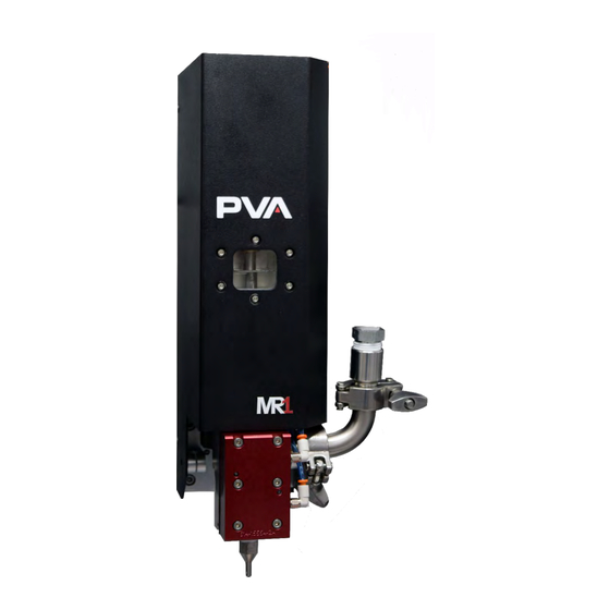
Page 25: F Igure 38: Mr1 With Cover
1 3 0 B 2 1 6 B F igure 38: MR1 with Cover 3 9 B I nstall the MR1 in the workstation or the workcell, as necessary. 1 3 1 B Page 25 of 33 Revision B June 2021... -
Page 26: Technical Specifications
MR1 Manual Technical Specifications Weight Approximately 6.8 kg (15 lbs) Material inlet 3/4’’ Sanitary Fitting Material outlet ¼’’ NPT T able 3: Technical Specifications 4 0 B Page 26 of 33 Revision B June 2021... -
Page 27: Troubleshooting
MR1 Manual Troubleshooting T his section is designed to help solve problems before you call PVA. Refer to this section if 2 1 7 B a mechanical or electrical problem occurs. T roubleshooting Problem P ossible Cause C orrective Action... -
Page 28: Damaged Pump Gasket
MR1 Manual Damaged Pump Gasket I f material leaks from between the air body and metering sleeve, on the side of the pump, 2 1 8 B the pump gasket is worn. To replace the pump gasket, do the steps below: U se a 3 mm hex wrench to remove six socket head bolts from the air section. - Page 29 MR1 Manual E xamine the pump gasket for any cracks or signs of wear on the side that was facing 1 3 5 B the metering sleeve. If the pump gasket is worn, it will be necessary to replace. DO NOT flip the pump gasket over or you can damage the pump.
-
Page 30: Calling Technical Support
2 2 3 B you can email cs@pva.net to create a support ticket. Before you contact PVA, have the following information: R ecord all the information on the OIT when the error occurred, include any error 1 4 0 B messages that may appear. -
Page 31: Notes
MR1 Manual Notes Page 31 of 33 Revision B June 2021... -
Page 32: Warranty
PVA (or from factory authorized dealers) will void all warranties. A ll PVA warranties extend only to the original purchaser. Third party warranty claims will not 2 2 7 B be honored at any time. -
Page 33: Table Of Figures
2 7 4 B F igure 37: Install Mounting Bolts ......................... 24 2 7 5 B F igure 38: MR1 with Cover ............................ 25 2 7 6 B F igure 39: Remove Bolts from Air Section ......................28 2 7 7 B F igure 40: Remove Air Section from Fluid Section ..................
Need help?
Do you have a question about the MR1 and is the answer not in the manual?
Questions and answers