
Related Manuals for Wenglor ZAC5 EN0 Series

Summary of Contents for Wenglor ZAC5 EN0 Series
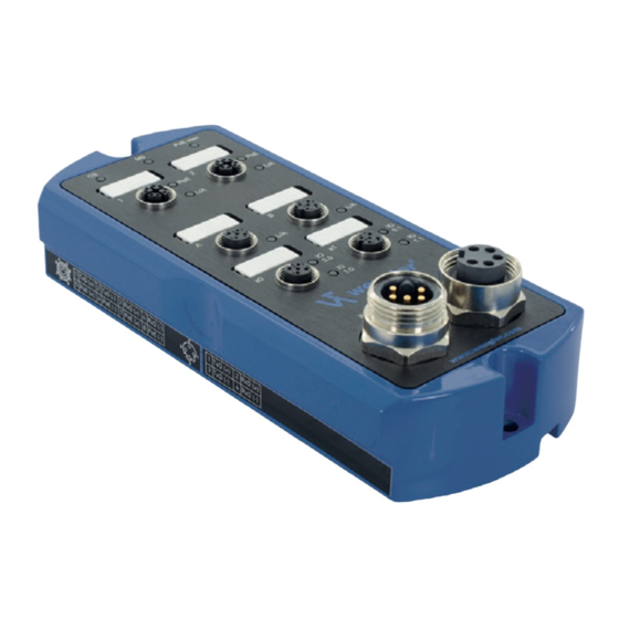
- Page 1 ZAC5xEN0x Ethernet Switches Operating instructions Available only as PDF Status: 12.09.2016 www.wenglor.com...
- Page 2 Index 1. Proper Use 2. Safety Precautions 3. Approvals and IP Protection 4. Technical Data 4.1. Connection table ZAC50EN0x 4.2. Connection table ZAC51EN01 4.3. Housing Dimensions 4.3.1 ZAC5xxN01 4.3.2 ZAC50xN02 4.4. Complementary Products 5. Application Notes 6. Mounting Instructions 7. Initial Operation 7.1.
- Page 3 8.11. Vendor-specific object (0x64) 8.11.1 Configuration assembly for ZAC50EN01 and ZAC50EN02 8.11.2 Configuration assembly for ZAC51EN01 8.12. Connections 9. Web-based Configuration 9.1. Call up the Administration Interface 9.2. Overview page 9.3. Device settings 9.4. Industrial Ethernet Ports Settings 9.5. Digital I/O Ports Settings 10.
-
Page 4: Proper Use
A Switch is an active network component which distributes data to the corresponding addressees within a network in a targeted fashion. wenglor switches are fitted optionally with additional Power over Ethernet tech- nology. The power supply is integrated into existing network connection by means of Power over Ethernet. As an addition to Industrial Ethernet, there are several digital inputs and outputs directly on the switch that can be activated or evaluated via the network. -
Page 5: Technical Data
4. Technical Data Order number ZAC50EN01 ZAC50EN02 ZAC51EN01 Supply voltage 18...32 V DC 18...32 V DC 18...32 V DC Max. Current Consumption Device * 0.3 A 0.25 A 0.3 A Max. Current Consumption System ** 2.2 A 0.3 A max. PoE Capacity 30 W 25 W –... - Page 6 Socket 3 Socket 3 +24 V DC Socket 4 Socket 4 Socket 4 Suitable Plug: Function www.wenglor.com 0 V DC 0 V DC +24 V DC U System +24 V DC U Digital I/O / Sensor Socket 1 Socket 2...
- Page 7 TxD (−) RxD (−) Socket 3 Suitable Plug: Socket 2 Socket 2 Function 0 V DC 0 V DC Socket 1 Socket 1 +24 V DC U System +24 V DC U Digital I/O / Sensor Socket 3 Socket 3 www.wenglor.com...
-
Page 8: Housing Dimensions
4.3. Housing Dimensions 4.3.1 ZAC5xxN01 4.3.2 ZAC50xN02... -
Page 9: Complementary Products
4.4. Complementary Products Connection plug, 7/8", 5-pin Order number: ZAT77NN01 Suitable Plug: Connection socket, 7/8", 5-pin Order number: ZAB78NN01 Suitable Plug: Connecting cable, 7/8", 5-pin Order number: ZAV78R201, Cable length: 2 m Suitable Plug:... - Page 10 Connecting line, 7/8", 5-pin Order number: ZAS78R601, Cable length: 10 m Suitable Plug: Connector Plug RJ45; 8-pin Order number: ZAT45NN01 Suitable Plug: Connection plug, M12×1; 8-pin Order number: ZAT50NN01 Suitable Plug:...
- Page 11 Connecting cable M12×1; 8-pin Order number: ZAV50R201, Cable length: 2 m Order number: ZAV50R501, Cable length: 5 m Suitable Plug: Order number: ZAV50R502, Cable length: 5 m Suitable Plug: Connecting line M12×1, 8-pin Order number: ZAS50R601, Cable length: 10 m Suitable Plug: Connection plug, M12×1, 4-pin Order number: ZAT51NN01...
- Page 12 Connecting cable M12×1; 4-pin; D-coding Order number: ZAV51R201, Cable length: 2 m Order number: ZAV51R601, Cable length: 10 m Suitable Plug: Order number: ZAV51R202, Cable length: 2 m Order number. ZAV51R602, Cable length: 10 m Suitable Plug: Connection and power supply cables M12×1;...
-
Page 13: Application Notes
In the event of improper use, the guarantee and liability claim against the manufacturer shall lapse. Information concerning which cables and accessories are approved for installation can be found at www.wenglor.com or are described in this manual. -
Page 14: System Structure
7.1. System Structure Industrial Ethernet Digital Digital I/O-Port I/O-Ports Power 7.2. Power Cable Power In Power Out Pin 1 Pin 1 Pin 2 Pin 2 Pin 3 Pin 3 24 V max. 9 A Pin 4 24 V max. 9 A Pin 4 System 24 V max. -
Page 15: Functional Earth
(for tightening torque see “Mounting Instructions” on page 13). 7.4. Industrial Ethernet Cable wenglor provides a variety of preassembled industrial Ethernet cables. To ensure cabling as simple and reliable as possible, we recommend using our preassembled Industrial Ethernet cables. -
Page 16: Connecting Digital Sensors And Actuators
7.5. Industrial Ethernet Cable with Power over Ethernet To ensure cabling as simple and reliable as possible, we recommend using our preassembled industrial Eth- ernet cables. It is also possible to interconnect two switches with PoE via the 8-pin network cable. The PoE supply should then be switched off on at least one of the two PoE ports (see “Industrial Ethernet Ports Settings”... - Page 17 7.7. Diagnosis Assignment example: PoE max PoE max Power Power Power 24 V In 24 V In 24 V Out 24 V In 24 V Out 24 V Out ZAC50EN01 ZAC50EN02 ZAC51EN01 7.7.1 LED Display EtherNet/IP Device (ZAC50EN0x) The status displays for the communication are marked on the switch with CS and MS. Designation Condition Function...
- Page 18 The LED display on the M12 sockets displays the diagnosis for the corresponding socket. Designation Condition Function Yellow PoE in operation PoE function switched off Yellow flashing Link exists Green Green flashing Communication Designation Condition Function Input UB at Pin 2/4 Yellow IO 0.0/IO 1.0 Output...
- Page 19 Designation Condition Function Green Link exists Communication via port Green flashing Designation Condition Function Input UB at Pin 2/4 Yellow Output Switching output at UB Pin 2/4 IO 0.0/IO 1.0 Output Short circuit at Pin 2/4...
- Page 20 For a detailed description for different controllers and for installation of the files or project planning of the net- work refer to the help files of the relevant controller. wenglor provides a short exemplary instruction for commis- sioning of an EtherNet/IP device (www.wenglor.com ...
-
Page 21: Identity Object (0X01)
8. Detailed description of the modules for EtherNet/IP devices 8.1. Identity object (0x01) This object provides the identification of the device. Identity Object (0x01) Class Attributes Name Access Revision Max Instance Number of Instances Maximum ID Number Class Attributes Maximum ID Number Instance Attributes Class Services Code Name... -
Page 22: Message Router Object (0X02)
8.2. Message router object (0x02) The Message router defines the connection paths to other objects and allows access to the objects via these paths. Message Router Object (0x02) Class Attributes Name Access Revision Max Instance Number of Instances Optional Attribute List Optional Service List Maximum ID Number Class Attributes Maximum ID Number Instance Attributes... -
Page 23: Assembly Object (0X04)
8.3. Assembly object (0x04) The assembly object links attributes of different objects so that they can be transmitted as a whole via a single connection. The following assemblies are available: Input assembly (producing) Output assembly (consuming) 37 Config assembly Assembly Object (0x04) Class Attributes Name Access... -
Page 24: Connection Manager Object (0X06)
8.4. Connection manager object (0x06) This object manages internal resources for maintaining explicit and implicit connections. Connection Manager Object (0x06) Class Attributes Name Access Revision Max Instance Number of Instances Optional Attribute List Maximum ID Number Class Attributes Maximum ID Number Instance Attributes Class Services Code Name... - Page 25 8.5. Discrete input point objects (0x08) This object manages a single physical input of the device. Discrete Input Point Object (0x08) Class Attributes Name Access Revision Max Instance Class Services Code Name 0x0E Get_Attribute_Single Instance Attributes Name Access Value (0=off, 1=on) Instance Services Code Name...
- Page 26 8.7. QoS object (0x48) The QoS (Quality of Service) object can be used to configure the DSCP values of the different outgoing mes- sage priorities QoS Object (0x48) Class Attributes Name Access Revision Max Instance Number of Instances Maximum ID Number Class Attributes Maximum ID Number Instance Attributes Class Services Code...
-
Page 27: Port Object (0Xf4)
8.8. Port object (0xF4) This object describes the existing CIP ports of the device. Port Object (0xF4) Class Attributes Name Access Revision Max Instance Number of Instances Maximum ID Number Class Attributes Maximum ID Number Instance Attributes Entry Port Port Instance Info Class Services Code Name... -
Page 28: Tcp/Ip Interface Object (0Xf5)
8.9. TCP/IP interface object (0xF5) This object implements mechanisms for configuration of the TCP/IP layer such as, for example, IP address, subnet mask, and gateway address. TCP/IP Interface Object (0xF5) Class Attributes Name Access Revision Max Instance Number of Instances Maximum ID Number Class Attri- butes Maximum ID Number Instance... -
Page 29: Ethernet Link Object (0Xf6)
8.10. Ethernet link object (0xF6) This object configures the connection-specific features (MAC ID, transmission rate, etc.) of the Ethernet inter- faces. Ethernet Link Object (0xF6) Class Attributes Name Access Revision Max Instance Number of Instances Maximum ID Number Class Attributes Maximum ID Number Instance Attributes Class Services Code... - Page 30 8.11. Vendor-specific object (0x64) The vendor-specific object 100 is used for configuration of the I/O ports and PoE ports etc. Vendorspecific Object (0x64) Class Attributes Name Access Keine Class Instanz vorhanden. Attribute 1 nicht benötigt da Revision == 1 Class Services Code Name Keine Class Instanz vorhanden...
-
Page 31: Web-Based Configuration
8.12. Connections One exclusive owner connection and several input/lists only connections are supported. The exclusive owner connection transmits exactly one byte in both directions. Up to four of the lower bits of this byte are valid for each direction. The maximum total number of valid bits for both directions corresponds to the number of physi- cal inputs and outputs of the device, i.e. - Page 33 To now access the webpage of the switch (in the example ZAC50EN01), the IP address must be entered as described in the address line of the browser. Example: http:\\192.168.100.1 The overview page Device General is not password-protected. If the pages of the device or port settings are accessed, a password prompt appears.
-
Page 34: Overview Page
9.2. Overview page After the connection is established, the overview page of the switch is displayed. Through the language selection, the website can be changed from English (delivery state) to German, Italian, French or Spanish. -
Page 35: Device Settings
9.3. Device settings Network settings: When a switch is not operated on a controller, it is possible to change the network settings. By default, IP ad- dress assignment is done via a DHCP server. In delivery condition, the network setting is set to “Obtain IP ad- dress automatically”. - Page 36 PoE information (ZAC50EN0x): The switch monitors the current PoE power consumption constantly. The webpage shows the maximum avail- able PoE performance of the switch as well as the currently reserved and outgoing PoE performance. Every PoE device registers in a specific PoE performance class when starting. This performance is then re- served in the switch.
- Page 37 9.4. Industrial Ethernet Ports Settings The Port Settings/Industrial Ethernet Ports page provides an overview of the individual ports of the switch. You can switch between the individual ports using the tab on the uppermost level. The Industrial Ethernet ports contain information on the number of packages received correctly and incorrectly as well as packages sent correctly.
- Page 38 9.5. Digital I/O Ports Settings The switch has 2 ports available with two digital inputs/outputs each. The digital inputs/outputs are configured on the Digital I/O Ports page. Pin 2 and pin 4 can each be configured as input or output. If the pin is configured as output, the pin can be set manually to 0 V or UB.
-
Page 39: Maintenance Instructions
GmbH does not accept the return of unusable or irreparable products. Respectively valid national waste disposal regulations apply to product disposal. 12. EU Declaration of Conformity The EU declaration of conformity can be found on our website at www.wenglor.com in download area. - Page 40 This operating manual is only a general description of technical processes whose implementation does not apply to every individual application.
Need help?
Do you have a question about the ZAC5 EN0 Series and is the answer not in the manual?
Questions and answers