Table of Contents
Advertisement
Quick Links
Advertisement
Table of Contents

Related Manuals for DIGITIZE Q-MUX

Summary of Contents for DIGITIZE Q-MUX
- Page 1 Q-MUX MULTIPLEX SYSTEM Digitize, Inc. 158 Edison Road Lake Hopatcong, New Jersey 07849 Tel: (973) 663-1011 Part Number: 700226-0001 Fax: (973) 663-4333 Revision: F E-mail: info@digitize-inc.com Issue Date: 05/11 Website: http://www.digitize-inc.com...
- Page 2 Digitize, Inc. 158 Edison Road Lake Hopatcong, NJ 07849-2217 The Digitize logo (stylized) is a registered trademark of Digitize, Inc.
- Page 3 E-Mail: info@digitize-inc.com Website: http://www.digitize-inc.com This manual has been prepared by DIGITIZE, INC. for use by its licensees, distributors and customers. The information contained herein is the property of DIGITIZE, INC. and may not be copied, disclosed or reproduced, in whole or in part, without the prior written approval of DIGITIZE, INC.
-
Page 5: Table Of Contents
Table of Contents 1 What is the Q-Mux System?..............1-1 2 Components of a Q-Mux System ............. 2-1 2.1 Q-EOL End-of-Line IDM ......................... 2-1 2.2 Q-1C, Digital Input IDM........................2-2 2.3 Q-1CL, Latched Input IDM ......................2-3 2.4 Q-1R, Relay Output IDM........................2-4 2.5 Q-I/O, Input/Output IDM........................ -
Page 7: What Is The Q-Mux System
ID modules. Up to 32 Q-Nodes may be used in one system. Total range of the Q-Mux system is 5,000 feet from the System 3505 to the last Q-Node and up to 5,000 feet from the Q-Node to the last ID module. ID modules may be set to any address from 1 to 99. - Page 8 Q-Mux Node Utility Software - Q-Mux Utility Software is a Q-Node diagnostic and address PC utility. The software allows the user to test Q-Mux Nodes and Input or Output devices connected to it from their computer and assign node addresses to the Q-Mux Nodes.
-
Page 9: Components Of A Q-Mux System
2 Components of a Q-Mux System 2.1 Q-EOL End-of-Line IDM Q-EOL IDM provides a direct interface between variable resistance inputs and the Q- Node controller. The module is used to monitor fire alarm and security devices. A 1.43K Ohm EOL resistor is included with the Q-EOL module. -
Page 10: Q-1C, Digital Input Idm
IDM is a transponder compatible with Digitize’s Q-Mux multiplex system. The module provides a direct interface between digital inputs and the Q-Mux Node controller. The four-wire module connects to the TBuss (2-wires) and to the contact that is to be monitored (2 wires). -
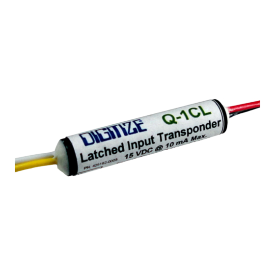
Page 11: Q-1Cl, Latched Input Idm
2.3 Q-1CL, Latched Input IDM Q-1C Q-1CL IDMs provide a direct interface between digital inputs and the Q-Mux controller. The Q-1C module can be programmed at the System 3505 to respond to normally open (NO) or normally closed (NC) inputs. -
Page 12: Q-1R, Relay Output Idm
A contact monitoring signal is sent back to the System 3505* indicating relay contact open, relay contact closed, or trouble (malfunction). Diagram of Q-1R IDM Digitize Part Number: 425182-0004 Dimensions: 2.75in. x 2.75in. x 1.5in; Open PCB Power Requirements: 15 VDC @ 10 milliamps max. -
Page 13: Q-I/O, Input/Output Idm
IDM provides a direct interface between digital inputs (contact closures) and he Q-Mux controller. It also provides a digital output that can be used to turn on/off an LED indicator. Power to the LED can either be provided from the TBuss (with some limitations), or from an external power supply. -
Page 14: Q-Snp-Eol-O/C Idm
Top View of Q-SNP-EOL-OC Bd. Diagram of Q-SNP-EOL-OC with a Mother Bds Digitize Part Number: 425182-0009 Dimensions: 1.75in. x .53in.; Open PCB Power Requirements: 15 VDC @ 10 milliamps max. Operating Environment: Install in a dry, indoor environment. -
Page 15: Q-Snp-Rly-Form C Idm
Module Q-SNP-RLY-FORM C provides a Form C (NO/COM/NC) relay contact output under control of the Q-Mux™ Central Buss Driver. A contact monitoring signal is sent back to the System 3505* indicating relay contact open, relay contact closed, or trouble (malfunction). -
Page 16: Q-Snp-Triple Idm Mother Board
The boards shown above have three SNP-EOL bds installed. (SNP-EOL bds not included. Ordered separately.) Digitize Part Number: 425182-0012 Dimensions: 3.22” x 2.69”; Open PCB. Mounting holes are 2.13” x 2.37”. Leds: Each SNP board has an Led mounted on the Mother Bd. -
Page 17: Q-Snp-16 Idm Mother Board
The board shown above has 16 SNP-EOL bds installed. (SNP-EOL bds not included. Ordered separately.) Digitize Part Number: 425182-0011 Dimensions: 3.50” x 19.00”; Open PCB mounted on sheetmetal. Leds: Each SNP board has an Led mounted on the Mother Bd. -
Page 18: Dual Eol Idm
Ohm EOL resistor is included with each of the two Q-EOL modules. Photo and Diagram of a Dual EOL IDM Bd. Digitize Part Number: 02-4033 Dimensions: 2.69 in. x 3.21in.; Open PCB. Mounting holes are 2.13” x 2.37” Power Requirements: 15 VDC @ 20 milliamps max. if both EOL IDMs are used. -
Page 19: Eol / Relay Idm
Photo and Diagram of an EOL / RELAY IDM Bds Digitize Part Number: 02-4032 Dimensions: 2.69 in. x 3.21in.; Open PCB. Mounting holes are 2.13” x 2.37” Power Requirements: 15 VDC @ 20 milliamps max. if both EOL IDMs are used. -
Page 20: Q-Node Controller
EEPROM. It is shipped pre-programmed to address #1. The field should reserve address #1 for use on the last Q-Node. The Q-Node address is programmed using the Q-Mux Utility Software. See Section 2.14. Layout & Diagram of Q-Node Controller 2-12... - Page 21 Components Digitize Inc. Q-Node Specifications Digitize Part Number: 425183-0004 Dimensions: 2.75in. x 2.75in; Open PCB Power Requirements: 10 – 14 VDC @ 300 milliamps max., Must be connected to a Regulated Power Supply, UL Listed for Fire Protective Signaling Systems (UL 1481).
-
Page 22: Q-Mux Idm Programmer
Digitize Inc. 2.13 Q-Mux IDM Programmer The Q-Mux programmer is intended for Digitize’s IDM modules. It will work with both the wired and the newer “SNP” IDMs. The Q-MUX PROGRAMMER provides the functionality to test and program Digitize’s family of IDM™s (Identification Modules). The IDMs are transponders that are compatible with Digitize’s T-Buss, a proprietary multiplex system. -
Page 23: Q-Mux Node Utility Software
2.14 Q-Mux Node Utility Software Q-Mux Utility Software is a Q-Node diagnostic and address PC utility. The software allows the user to test Q-Mux Nodes and Input or Output devices connected to it from a computer. The software allows the user to: 1. - Page 24 Components Digitize Inc. This page is intentionally blank. 2-16 700226-0001 Rev. F 05/11...
-
Page 25: Considerations For A Q-Mux System
3 Considerations for a Q-Mux System Below are a few of the items to consider when planning to implement a Q-Mux System. 3.1 Type of Inputs Required What type of input IDMs are needed? Does the connection to the input IDM need to be... -
Page 26: What Is The Q-Node Going To Placed In And How Will It Be Powered
Components Digitize Inc. 3.4 What is the Q-Node going to placed in and how will it be powered? The Q-Nodes are open pcb controllers. Installers will need to consider several items when installing them: 1. Enclosure – What will the Q-Node be installed in? 2. -
Page 27: Setting Up The 3505 Hardware
4 Setting up the 3505 Hardware In order to get the Q-Mux system working with a System 3505, you need to have the following: 4.1 Q-Mux Software Option If you did not purchase the Q-Mux Software Option for your System 3505, you will not be able to connect the System 3505 with the Q-Nodes and make them communicate. -
Page 28: Rs-485 Line Driver Board And Rack
Four RS-485 Line Driver Cards installed in a Line Driver Rack. The Diagram below shows a typical Style 3 Q-Mux System using two Line Driver cards. The benefits of using a line driver rack are that the two RS-485 connections are completely isolated. - Page 29 Typical Q-Mux System with a RS-485 Line Driver Card, Style 3 Below is a typical Q-Mux System using Style 6 Rs-485 connections. Each RS-485 Line Driver board is style 6 capable. In the Style 6 configuration, the RS-485 signal makes an entire loop.
- Page 30 3505 Hardware Digitize Inc. Each Line driver Card has a removable RS-485 connector on the back. All of the connections from the System 3505 and the Line Driver Rack are also on the back. Each connection is marked “A” and “B” and has polarity.
-
Page 31: Setting Up The 3505 Firmware
By pressing the SET button, the operator may step through all available menus. If pressed for over one second, the SET button will auto repeat. Direct access to the Q-MUX menu is possible by entering the menu number (24) and pressing the SET button. After pressing 24 SET, the display will read: 5.1 Password... -
Page 32: Setup Screen
Once the password has been entered at this level the operator can move between screens without reentering the password. Enter password and press SET and the Q-MUX setup screen will appear. 5.2 Setup Screen After the password has been entered and the SET button has been pressed, the SETUP screen will appear and the display will read: The operator must enter ‘1’... -
Page 33: Add/Chg/Del Id
3505 Firmware Digitize Inc. 5.2.2 Add/Chg/Del ID At the SETUP screen, enter 1 (ADD/CHG/DEL) and the display will read: This section of the setup screen is for programming the Node and IDM information into the System 3505. This will affect how the information is displayed on the System 3505. - Page 34 3505 Firmware Digitize Inc. After setting the Node number, press Func to advance to the next field, in this case it is the “=NONE”. This sets whether the Node is used for Fire, Burg, or Other applications. Use ↑↓ keys to select NONE, FIRE, BURG or OTHER for node.
- Page 35 3505 Firmware Digitize Inc. DRVR# - This field selects which line driver card to use. Select NONE when using a configurator card on the back of the system 3505. Use ↑↓ keys to select the line driver card number. The line driver card number can be set from 1 to 32.
-
Page 36: Set Tamper Use
3505 Firmware Digitize Inc. 5.2.3 Set Tamper use Each Q-Node is fitted with a Tamper input which when used would be connected to a Normally closed switch on the Q-Node enclosure. This Setup screen will determine if the system 3505 will be reporting the status of the Tamper switch. -
Page 37: Getting The System Up And Running
IDM numbers are duplicated. b. Connect Q-Node to Q-Mux Node Utility Software – The Q-Mux Node Utility Software is an essential tool when setting up a Q-Mux system. It is used to program the Q-Node number and perform diagnostics on the Q-Node and IDMs. - Page 38 Getting the System Running Digitize Inc. running. Pay special attention to the polarity of the wires for the TBUSS. Connecting them one at a time makes it much easier to identify potential issues then if the entire loop was connected and tested at once.
-
Page 39: Advanced Settings & Options
The SYSTEM 3505 has the ability to transmit the SST code via the Q-1R or Q-I/O module. To transmit the SST box via the Q-Mux option, the SST 3505 option and the Zone to Code SST 4000 options must be installed in the SYSTEM 3505. - Page 40 Advanced Settings & Options Digitize Inc. The SST SLOW relay will code out the same box number as the Q-IR or Q-I/O device. Pressing the STOP key will abort both the SST SLOW and the SST to the Q- Mux device. If you wish to transmit only via the SST SLOW (or FAST), use the @B command in place of the @Q command.
-
Page 41: Trouble Shooting The Q-Mux
Cannot use 24 SET Menu. If the software option was installed on the System 3505 you will not be able to use the 24 Set Menu. You will need to contact your distributor or Digitize to arrange to have the Q-Mux software installed. -
Page 42: Idm Issues
Not connected to the correct port on the System 3505. With reference to software settings on the System 3505: The Q-Mux port has not been configured properly. The port has been programmed but not activated. Try a hard restart of the System 3505. - Page 43 3505 Firmware Digitize Inc. functional. Next connect the IDM to the Q-Node at the Q-Node’s location. If that works look to the connection between the Q-Node and IDM to be the problem. Input IDM fails to change state. The IDM is either not communicating with the Q-Node or the part is bad and needs to be replaced.
- Page 44 Trouble Shooting Digitize Inc. This page is intentionally blank. 700226-0001 Rev. F 05/11...
-
Page 45: What Is The Mystery Symbol
"cells" or modules arranged in a square pattern. The Data Matrix above would direct you to the Wikipedia web site on Data Matrixes. The Data Matrixes placed in this manual will direct you to the Digitize web page that contains more information on the subject you were reading about. - Page 46 This page is intentionally blank. 700226-0001 Rev. F 05/11...
- Page 47 10 Appendix A The following pages contain reference drawings for the Q-Mux System. 700226-0001 Rev. F 05/11 10-1...
- Page 50 Digitize by telephone or in writing. Buyer will prepay all freight charges to return any products to the repair facility designated by Digitize and include the RMA number on the shipping container. Digitize will, at its option, either repair the defective products or parts or deliver replacements for defective products or parts on an exchange basis to Buyer, freight prepaid to the Buyer.
Need help?
Do you have a question about the Q-MUX and is the answer not in the manual?
Questions and answers