
Related Manuals for GÜDE Expert PDU Energy 8340 Series

Summary of Contents for GÜDE Expert PDU Energy 8340 Series
- Page 1 Manual Expert PDU Energy 8340 Series Expert PDU Energy 8341 Series © 2021 GUDE Systems GmbH Manual Ver. 1.8.0 from Firmware Ver. 1.8...
- Page 2 Expert PDU Energy 8340/8341 © 2021 GUDE Systems GmbH...
-
Page 3: Table Of Contents
Table of contents Device Description Security Advice ....................... 6 Content of Delivery ....................6 Description ......................6 Installation ......................7 Hotswap Drawer ..................... 8 Technical Specifications ..................9 1.6.1 Electrical Measurement ................... 9 Sensor ........................10 Operating Operating the device directly ................14 Control Panel ...................... - Page 4 Table of contents IP ACL ........................46 IPv6 ........................47 Radius ........................47 SNMP ........................48 4.6.1 Device MIB 8340 ....................50 4.6.2 Device MIB 8341 ....................52 SSL ........................53 Console ......................... 55 4.8.1 SSH ......................... 59 4.8.2 Cmd 8340 / 8341 ....................59 Modbus TCP ......................
- Page 5 Device Description...
-
Page 6: Device Description Security Advice
Device Description Device Description Security Advice · The device must be installed only by qualified personnel according to the following installation and operating instructions. · The manufacturer does not accept responsibility in case of improper use of the device and particularly any use of equipment that may cause personal injury or ma- terial damage. -
Page 7: Installation
Device Description · Measurement of residual current for all phases (models 8340-2, 8341-2) · Hot Swap Drawer - The device electronics, including power supply, can be replaced on a drawer without the need to turn off the PDU consumers · Connecting of two optional external sensors to determine the temperature and hu- midity, or a input switch ·... -
Page 8: Hotswap Drawer
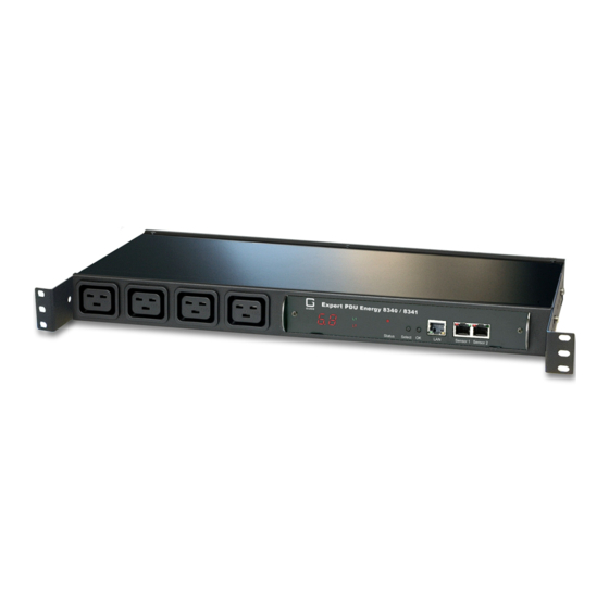
Device Description 1. - 4. Load outputs for phases L1 to L4 (IEC C19, max. 16 A) Rear of the device 1. - 4. Load inputs for phases L1 to L4 (IEC C20, max. 16 A) 5. Mains supply (IEC C14, max. 10 A) Start-up the device ·... -
Page 9: Technical Specifications
Device Description Technical Specifications Interfaces 1 x Ethernet port (RJ45) 1 x Mains supply (IEC C14, max.10 A) 4 x Load inputs (IEC C20, max. 16 A) 4 x Load outputs (IEC C19, max. 16 A) 2 x RJ45 for external sensor Network connectivity 10/100 MBit/s 10baseT Ethernet Power Supply... -
Page 10: Sensor
Device Description Sensor Two external sensors can be connected to the Expert PDU Energy 8340 / 8341. The following sensors are currently available Humidity/Temperature Sensor 7102 (End-of-Life) Cable length Connector RJ45 temperature range -20°C to +80°C, ±0,5°C (maximum) and ±0,3°C (typical) air humidity range 0-100%, ±3% (maximum) and ±2% (typical) (non-condensing)) - Page 11 Device Description Product Name 7101 7104-1 7105-1 7106-1 Calibrated 7104-2 7105-2 7106-2 Sensor Cable length Connector RJ45 RJ45 RJ45 RJ45 temperature range -20°C to +80°C at -20°C to +80°C at -20°C to +80°C at -20°C to +80°C at ±2°C (maximum) ±2°C (maximum) ±2°C (maximum) ±2°C (maximum)
- Page 12 Device Description Expert PDU Energy 8340/8341 © 2021 GUDE Systems GmbH...
-
Page 13: Operating
Operating... -
Page 14: Operating The Device Directly
Operating Operating Operating the device directly Power Indicator If the current is shown on the 7-segment display (see Configuration - sensor ), then the measured current values of all phases are displayed in sequential order. When no voltage is measured (smaller 70V) the display will show three dashes, and the green plain text displays L1 to L4 are off. -
Page 15: Maintenance
Operating Maintenance The actual device generation with IPv6 and SSL allows all maintenance functions in the web interface to be carried out on the Maintenance Page Maintenance in the web interface The following functions are available from the maintenance web page: ·... -
Page 16: Maintenance Page
Operating The GBL_Conf.exe program is available free of charge on our website www.gude.info and can also be found on the enclosed CD-ROM. Interface GBL_Conf To check the network settings with GBL_Conf.exe, start the program and choose "All Devices" in the "Search" menu. From the list select the appropriate device. The lower part of the left half of the window now shows the current network settings of the device. - Page 17 Operating Firmware Update: Start a firmware update. SSL Certificate Upload: Saves your own SSL certificate. See chapter "SSL " for the generation of a certificate in the right format. Config Import File Upload: Loads a new configuration from a text file. To apply the new configuration, a "Restart Device"...
-
Page 18: Configuration Management
Operating Config/Status View: status.html: Displays the status.html page with the JSON data. Config/Status Download: export.json: Direct file download of JSON data from status.hml. 2.3.2 Configuration Management The device configuration can be saved and restored in the maintenance area The "Config File Export" function can be used to save the current configuration as a text file. -
Page 19: Bootloader Activation
Operating completely configured. Configuration via Telnet The configuration files can in principle also be transferred in a Telnet session, but then the settings are changed during operation, and not completely when restarting, as it would have been the case with an upload. It can happen that events are triggered at the same time as the device is configured. - Page 20 Operating pendix "BOOT-LDR" after the device name). In Bootloader mode the program "GBL_Conf.exe" can disable the password and the IP ACL, perform a firmware update, and restore the factory settings. For devices with relays, entering or exiting the bootloader mode does not change the state of the relays as long as the operating voltage is maintained.
-
Page 21: Configuration
Configuration... -
Page 22: Ethernet
Configuration Configuration TCP/IP configuration by DHCP After switching on the device is scanning on the Ethernet for a DHCP server and re- quests an unused IP address. Check the IP address that has been assigned and ad- just if necessary, that the same IP address is used at each restart. To turn off DHCP use the software GBL_Conf.exe or use the configuration via the web interface. - Page 23 Configuration IPv4 Gateway address: The IP address of the gateway. IPv4 DNS address: The IP address of the DNS server. Use IPv4 DHCP: Select "yes" if the TCP/IP settings should be obtained directly from the DHCP server: When the function is selected, each time the device powers up it is checked if a DHCP server is available on the network.
-
Page 24: Ip Acl
Configuration 3.1.2 IP ACL Reply ICMP ping requests: If you enable this feature, the device responds to ICMP pings from the network. Enable IP filter: Enable or disable the IP filter here. The IP filter represents an access control for incoming IP packets. Please note that when IP access control is enabled HTTP and SNMP only work if the appropriate servers and clients are registered in the IP access control list. -
Page 25: Http
Configuration 3.1.3 HTTP HTTP Server option: Selects whether access is possible only with HTTP, HTTPS, or both. Server port HTTP: Here can be set the port number of the internal HTTP. Possible val- ues are from 1 to 65534 (default: 80). If you do not use the default port, you must ap- pend the port number to the address with a colon to address the device from a web browser. -
Page 26: Protocols
Configuration Use locally stored passwords: Username and password are stored locally. In this case, an admin password and a user password must be assigned. The password can have a maximum of 31 characters. The name "admin" and "user" are provided for the user name in the password entry mask of the browser. -
Page 27: Syslog
Configuration Telnet TCP port: Telnet sessions are accepted on this port. Raw mode: The VT100 editing and the IAC protocol are disabled. Activate echo: The echo setting if not changed by IAC. Active negotiation: The IAC negotiation is initiated by the server. Require user login: Username and password are required. - Page 28 Configuration SNMP-get: Enables the acceptance of SNMP-GET commands. SNMP-set: Allows the reception of SNMP-SET commands. SNMP UDP Port: Sets the UDP port where SNMP messages are received. sysContact: Value of RFC 1213 sysContact. sysName: Value of RFC 1213 sysName. sysLocation: Value of RFC 1213 sysLocation. Enable SNMP v2: Activates SNMP v2.
-
Page 29: Radius
Configuration SNMP v3 Authorization Algorithm: The selected Authentication Algorithm. SNMP v3 Privacy Algorithm: SNMP v3 Encryption Algorithm.. If the password mask is redisplayed, only four "bullets" are shown as a symbolic placeholder, since for security reasons the device never stores the password itself, but only the key formed using the Authorization Algorithm. -
Page 30: Modbus Tcp
Configuration Use CHAP: Use CHAP password encoding. Use Message Authentication: Adds the "Message Authentication" attribute to the Authentication Request. Primary Server: Name or IP address of the Primary Radius server. Shared secret: Radius Shared Secret. For compatibility reasons, only use ASCII char- acters. -
Page 31: Mqtt
Configuration Enable Modbus TCP: Enables Modbus TCP support. Modus TCP port: The TCP/IP port number for Modbus TCP. 3.2.6 MQTT Enable MQTT: Enables MQTT support. Broker: DNS or IP address of the MQTT broker. TLS: Turns on TLS encryption. Mode TCP port: The TCP/IP port number of the broker. Username: The MQTT username. -
Page 32: Clock
Configuration Keep-alive ping interval: This defines the time interval in which the client sends an MQTT ping. Topic prefix: Defines the beginning of the topic with which all messages are sent. The strings [mac] and [host] symbolize the MAC address or the hostname of the device. Permit CLI commands: Enables the execution of console commands. -
Page 33: Timer
Configuration Enable Time Synchronization: Enables the NTP protocol. Primary NTP server: IP address of the first NTP server. Backup NTP server: IP address of the second NTP server. Used when the first NTP server does not respond. Timezone: The set time zone for the local time. Daylight Saving Time: If enabled, the local time is converted to Central European Sum- mer Time. - Page 34 Configuration tion CLI" available, and not the register "Action PortSwitch". Creating a simple timer If you activate "New Rule: simple Timer" the following dialog is displayed: You set here which port should be switched for which time period, and on which days of the week the rule is active.
- Page 35 Configuration If you create a complex timer or change an existing timer, you will always see an ex- tended dialog: You can see here the extended representation of the first rule of the simple timer from the previous example. The action is started every day of every month at 9:30. The weekdays Saturday and Sunday are excluded.
- Page 36 Configuration The switching function can be set in more detail on the "Action PortSwitch" register. Port 1 is switched on. You could extend the rule and switch more ports on or off. Addi- tionally you can set a time for a batchmode in the field after "Between Action1 and Ac- tion 2 : wait", which starts "Action 2"...
- Page 37 Configuration To change a field in this input mask without changing the state of the other fields, the Ctrl key must be pressed during the mouse click. For this rule, on the "Options" tab, the time period is limited to the range between 5.10.2021 and 5.4.2022.
- Page 38 Configuration Instead of switching a port, one or more console commands can be executed. These commands are entered in the "Action CLI" register. The "Action Cli" tab can only be se- lected if the option "Perform CLI Cmd" is activated in "Options". Example Switching a Port on a Date If you want to switch on a timer on a certain date at a certain time and switch it off at a later time, you cannot do it directly with a simple timer.
- Page 39 Configuration Then call up the two timer rules you created ("On" and "Off") and enter the date on which the switching operation is to take place in the "Options" tab. Example blind control You can use the jitter e.g. for a shutter control. In the classic example of a shutter con- trol, you do not always want to raise and lower the shutters at the same time in order to confuse potential burglars.
-
Page 40: Sensors
Configuration Sensors Sensor: Selects a type of sensor to configure it. The first digit "1" indicates the number of the sensor port (only important for devices with more than one sensor port). This is followed by the sensor name, and the changeable sensor name. Sensor Name: Changeable name for this sensor. -
Page 41: E-Mail
Configuration Enable beeper for AC alarms: Activates the beeper for all AC limit messages. Enable beeper for sensor alarms: Activates the beeper for all sensor limit messages. Hysteresis Example: A Hysteresis value prevents that too much messages are generated, when a sensor value is jittering around a sensor limit. -
Page 42: Front Panel
Configuration port, e.g: "mail.gmx.net:25". SMTP server port: The port address of the E-Mail server. In the normal case this should be the same as the default, that is determined by the setting SMTP Connection Security. SMTP Connection Security: Transmission via SSL or no encryption. SMTP Authentification (password): Authentication method of the E-Mail Server. -
Page 43: Specifications
Specifications... -
Page 44: Automated Access
Specifications Specifications Automated Access The device can be accessed automatically via four different interfaces, which offer dif- ferent possibilities to access the configuration data and status information. Only http and the console (telnet and serial) provide full access to the device. This chapter is general for all Gude devices. - Page 45 Specifications · Syslog messages E-Mail messages Email messages are triggered by the following events: · Switching of the Ports · Exceeding of the max / min values of attached sensors · State change of digital sensor input ports SNMP Traps SNMP Traps are system messages that are sent via the SNMP protocol to different re- cipients.
-
Page 46: Ip Acl
Specifications conveyed by the supplied data within the trap. MQTT published data Messages on the MQTT channel are sent in JSON format. Example switch a port: "{"type": "portswitch", "idx": 2, "port": "2", "state": 1, "cause": {"id": 2, "txt": "http"}, "ts": 1632}" Console Push Messages Push messages can be activated on the console channels (Telnet, SSH or serial con- sole), which output sensor values at timed intervals (every n seconds) or as of a con-... -
Page 47: Ipv6
Specifications IPv6 IPv6 Addresses IPv6 addresses are 128 bit long and thus four times as long as IPv4 addresses. The first 64 bit form a so-called prefix, the last 64 bit designate a unique interface identifier. The prefix is composed of a routing prefix and a subnet ID. An IPv6 network interface can be reached under several IP addresses. -
Page 48: Snmp
Specifications HTTP Login The HTTP login takes place via Basic Authentication. This means that it is the respons- ibility of the web server, how long the login credentials are temporarily stored there. The RADIUS parameter "Session-Timeout" therefore does not determine when the user has to login again, but at what intervals the RADIUS servers are asked again. - Page 49 Specifications The algorithms "HMAC-MD5-96" and "HMAC-SHA-96" are available for authentication. In addition, the "HMAC-SHA-2" variants (RFC7630) "SHA-256", "SHA-384" and "SHA- 512" are implemented. "SHA-384" and "SHA512" are calculated purely in software. If "SHA-384" or "SHA- 512" is set on the configuration page, the time for the key generation may take once up to approx.
-
Page 50: Device Mib 8340
Specifications able bindings. In order to recognize this change directly, the "Notification" area in the MIB table has been moved from sysObjectID.0 to sysObjectID.3. This way, unidentified events are generated until the new MIB table is imported. For compatibility reasons, SNMP v1 traps are created in the same way as before. - Page 51 Specifications Index of Power Channel entries pdu8340ChanStatus .54.1.5.1.2.1.2.x Integer32 0 = data not active, 1 = data valid pdu8340AbsEnergyActive .54.1.5.1.2.1.3.x Unsigned32 Absolute Active Energy counter. pdu8340PowerActive .54.1.5.1.2.1.4.x Integer32 Active Power pdu8340Current .54.1.5.1.2.1.5.x Unsigned32 Actual Current on Power Channel. pdu8340Voltage .54.1.5.1.2.1.6.x Unsigned32 Actual Voltage on Power Channel pdu8340Frequency...
-
Page 52: Device Mib 8341
Specifications difference between dew point and actual temperature (Temp - DewPoint) pdu8340ExtSensorName .54.1.6.1.1.32.x OCTETS A textual string containing name of a external Sensor 4.6.2 Device MIB 8341 Below is a table of all device-specific OID 's which can be accessed via SNMP. In the numerical representation of the OID the prefix "... -
Page 53: Ssl
Specifications pdu8341ForwEnergyReactiveRese .65.1.5.1.2.1.19.x Unsigned32 ttable Resettable Forward Reactive Energy counter. pdu8341RevEnergyActive .65.1.5.1.2.1.20.x Unsigned32 Reverse Active Energy counter. pdu8341RevEnergyReactive .65.1.5.1.2.1.21.x Unsigned32 Reverse Reactive Energy counter. pdu8341RevEnergyActiveResettab .65.1.5.1.2.1.22.x Unsigned32 Resettable Reverse Active Energy counter. pdu8341RevEnergyReactiveResett .65.1.5.1.2.1.23.x Unsigned32 able Resettable Reverse Reactive Energy counter. pdu8341ResidualCurrent .65.1.5.1.2.1.24.x Unsigned32... - Page 54 Specifications Creating your own Certificates The SSL stack is supplied with a specially newly generated self-signed certificate. There is no function to generate the local certificate anew at the touch of a button, since the required ran- dom numbers in an embedded device are usually not independent enough. However, you can create new certificates and import them to the device.
-
Page 55: Console
Specifications cat server.crt IM1.crt IM2.crt server.key > server.pem An uploaded certificate will be preserved, when a device is put back to factory de- faults Performance Considerations If RSA 4096 certificates are used, the first access to the web server can take 8-10 seconds, because the math unit of the embedded CPU is highly demanded. - Page 56 Specifications http server set https_only http server set 1 http server set https_both http server set 0 Numerical parameters can be entered with different bases. Here is an example of the decimal value 11: Base Input decimal (10) hexadecimal (16) octal (8) binary (2) 0b1011...
- Page 57 Specifications turns. The command "vt100 numeric set ON" enables that only numerical values appear. Comments If you use a tool to send an entire file of commands via Telnet, it is helpful, if you can place comments in there. Beginning with the comment character "#", the remaining contents of a line is ignored.
- Page 58 Specifications sign corresponds to the Index field in the External Sensor Table. >extsensor 1 0 value show Displays temperature of the sensor at Port 1 b) Line Sensors >linesensor all "0,1,2,3,12" show L=1,L="Power Port",0="13000Wh",1="0W",2="225V",3="0A",12="998218s" L=2,L="Power Port",0="13000Wh",1="0W",2="223V",3="0A",12="996199s" This command outputs all line sensor values in one line. A list of all fields (according to the energy sensor table) is transferred as parameter.
-
Page 59: Ssh
Specifications 4.8.1 The device supports SSH-2 connections with either public key authentication or user name and password. The "login" must be enabled for SSH. Users and passwords can be stored locally or retrieved via a radius server. If you want to use SSH in a terminal, Activate echo should be enabled. - Page 60 Specifications clock timezone set {minutes} sets timezone clock timezone show shows timezone clock dst enabled set {OFF=0|ON=1} enables dst clock dst enabled show shows if dst is enabled clock manual set "{hh:mm:ss yyyy-mm-dd}" sets time and date manually clock show shows actual time and date clock ntp server {PRIMARY=0|BACKUP=1} set sets ntp server name...
- Page 61 Specifications ethernet phyprefer set {10MBIT_HD=0| sets preferred speed for PHY Auto Negotiation 10MBIT_FD=1|100MBIT_HD=2|100MBIT_FD=3} ethernet phyprefer show shows preferred speed for PHY Auto Negotiation extsensor enters cmd group "extsensor" extsensor all show shows all values from connected external sensors extsensor all show shows all plugged sensors and fields extsensor {port_num} {sen_field} value show shows sensor value...
- Page 62 Specifications http passwd enabled set {OFF=0|ON=1} enables http password on/off http passwd enabled show shows if http password enabled http passwd local set {OFF=0|ON=1} enables local login on/off http passwd local show shows if local login enabled http passwd radius set {OFF=0|ON=1} enables login for RADIUS on/off http passwd radius show shows if RADIUS login enabled...
- Page 63 Specifications beeper mode show linesensor {line_num} {energy_sensor} maxval set sets maximum value for line meter {float} linesensor {line_num} {energy_sensor} maxval shows maximum value for line meter show linesensor {line_num} {energy_sensor} minval set sets minimum value for line meter {float} linesensor {line_num} {energy_sensor} minval shows minimum value for line meter show linesensor {line_num} {energy_sensor} hyst set...
- Page 64 Specifications {num_secs} mqtt {broker_idx} device data timer show shows telemetry interval radius enters cmd group "radius" radius {PRIMARY=0|SECONDARY=1} enabled enables radius client set <off=0/on=1> radius {PRIMARY=0|SECONDARY=1} enabled show if radius client enabled show radius {PRIMARY=0|SECONDARY=1} server set sets radius server address "<dns_name>"...
- Page 65 Specifications system enters cmd group "system" system beeper manual set {OFF=0|ON=1} manually sets beeper with optional duration {millisec} system beeper manual show shows beeper state system restart restarts device system fabsettings restore fab settings and restart device system bootloader enters bootloader mode system flushdns flush DNS cache system uptime...
- Page 66 Specifications 3. The output may show 2 lines - the 1st line shows the actual state, the 2nd line the status after reboot 4. The output may show several lines 5. Please see the Energy Sensor Table for the right energy index 6.
-
Page 67: Modbus Tcp
Specifications Modbus TCP If Modbus TCP is activated in the configuration, the ports (relays, outputs, eFuses) can be switched and the following data is callable: Address range overview: Device Resource Start Modbus Data Type Power/Output/eFuse Ports 0x000 0x3ff Coils DC Inputs 0x400 0x7ff Discrete Inputs... - Page 68 Specifications Coils Device Resource Start Device Function Power/Output/eFuse 0x000 0x3ff Coil represens Port State Discrete Inputs Device Resource Start Function when set DC Inputs 0x400 0x7ff Input logically 1 Stop Condition active 0x800 0x800 Stop Input active POE active 0x801 0x801 POE active Status Power Sources...
- Page 69 Specifications 0x080 to 0x083 16-bit (signed CPU Sensor values 0x100 to 0x1ff 16-bit (signed) external Sensors 0x400 to 0x39ff 32-bit (signed) Line Energy Sensors 0x3a00 to 0x81ff 32-bit (signed) Port Energy Sensors 0x8200 to 0x823f 16-bit (signed) Bank Energy Sensors 0x8240 to 0x827f 16-bit (signed) Power Source Energy Sensors...
- Page 70 Specifications Examples: "Power Active" for 1st line sensor and 3rd phase: 0x400 + 0 * 0x120 + 2 * 0x60 + 1 * 2 = 0x4C2 "Voltage" for 2nd line sensor and single phase device: 0x400 + 1 * 0x120 + 2 * 2 = 0x524 "Power Angle"...
- Page 71 Specifications Offset Sensor Field Unit Voltage 0.01 V Current Residual Current Monitor Type B (RCMB): Devices with a Residual Current Monitor Type B (RCMB) module separately measure the RMS and DC fault current components of the input supply. The values are returned as signed 16-bit integers.
-
Page 72: 4.10 Mqtt
Specifications NextObjectID 1 Byte 0x00 Number of Objects 1 Byte 0x03 Object ID 1 Byte 0x00 Object Length 1 Byte Object Value n1 Bytes "Company Id" Object ID 1 Byte 0x00 Object Length 1 Byte Object Value n2 Bytes "Product Id" Object ID 1 Byte 0x00... - Page 73 Specifications As default the execution of commands is not allowed, but must be enabled in the MQTT configuration! ("Permit CLI commands") Format 1: Command in JSON Syntax Publish Topic: "de/gudesystems/epc/00:19:32:01:16:41/cmd" Publish Message: "{"type": "cli", "cmd": "port 2 state set 1", "id": 10}" Response from device to "de/gudesystems/epc/00:19:32:01:16:41/cmdres"...
-
Page 74: 4.10.1 Example Hivemq
Specifications "name": "Power Port", "state": 0 "line_in": [{ "voltage": 242.48, "current": 0.000 "sensors": [{ "idx": 1, "name": "7105", "data": [{ "field": "temperature", "v": 21.1, "unit": "deg C" }, { "field": "humidity", "v": 71.9, "unit": "%" }, { "field": "dew_point", "v": 15.8, "unit": "deg C"... - Page 75 Specifications In the MQTT configuration of the Gude device, transfer the hostname of the HiveMQ broker, as well as username and password. Additionally activate TLS and set the cor- rect port. Expert PDU Energy 8340/8341 © 2021 GUDE Systems GmbH...
-
Page 76: Support
Support... -
Page 77: Data Security
Support Support You will find the latest product software on our website at www.gude.info available for download. If you have further questions about installation or operation of the unit, please contact our support team. Furthermore, we present in our support wiki at www.gude.info/wiki FAQs and configuration examples. -
Page 78: Declaration Of Conformity
Support WEEE-number: DE 58173350 Value added tax identification number (VAT): DE 122778228 Declaration of Conformity This product from the Expert PDU Energy 8340 / 8341 series is in conformity with the European directives for CE marking applicable to this product. The complete CE de- claration of conformity for this product can be found on the website www.gude.info in the download section of the product. - Page 79 Support 5. Can you enter multiple e-mail recipients? · Yes. In the E-Mail configuration in the Recipient Address field, it is possible to enter multiple e-mail addresses separated by commas. The input limit is 100 characters. 6. Why did the MIB tables change after the firmware update? ·...
-
Page 80: Index
Index - A - - I - automated Access Installation IP-ACL 24, 46 - B - IP-Address IPv6 Bootloader Mode 15, 19 - L - Button Lock - C - load Configuration - M - Certificate-Upload 15, 16 clear DNS-Cache Configuration Management Maintenance Content of Delivery... - Page 81 Index Timer Timer Configuration Expert PDU Energy 8340/8341 © 2021 GUDE Systems GmbH...
- Page 82 Expert PDU Energy 8340/8341 © 2021 GUDE Systems GmbH 11/18/2021 Expert PDU Energy 8340/8341 © 2021 GUDE Systems GmbH...
Need help?
Do you have a question about the Expert PDU Energy 8340 Series and is the answer not in the manual?
Questions and answers