
Subscribe to Our Youtube Channel
Related Manuals for Advanced Axis AX-ASW-16


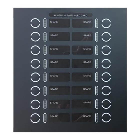
Summary of Contents for Advanced Axis AX-ASW-16
- Page 1 Switch LED Modules AX-ASW-16 AX-I/O-48 AX-LED16RY AX-LED32R / AX-LED32Y www.advancedco.com...
-
Page 2: Table Of Contents
Table of Contents Page INTRODUCTION / OVERVIEW ..........................3 ..........................3 RODUCT ESCRIPTION MODULE INSTALLATION ...........................4 ........................4 NCLOSURE OUNTING AX-LZA C .........................5 ABINET OUNTING AX-I/O-48 O ......................6 THER ABINET OUNTING 2.3.1 AX-GCAB Mounting ..........................6 MODULE DIP SWITCH CONFIGURATION ......................7 (4 DIP S ) ........................7 DDRESSING WITCHES... -
Page 3: Introduction / Overview
The Axis Switch LED Modules are extremely flexible and easy to configure/program utilizing the Advanced PC- NeT field configuration tool, which works in a Windows® environment. Switches can be programmed to bypass (disable/enable) points, zones, and/or groups. They can also be programmed to turn On/Off relay points, NAC circuits, city connections, or they can be configured to provide complete HOA (Hand-Off-Auto) control functionality. -
Page 4: Module Installation
2 Module Installation 2.1 Axis Enclosure Mounting The Switch LED Modules can be mounted into any available inner (AX-CTL-1 outer) door aperture of an Axis enclosure (see figure 1). AX-CTL-1 Inner (AX-CTL-1 AX-CTL-1V, 2V or 4V AX-CTL-1L, 2 or 4 outer) door opening/slot AX Command Center (3x3) -
Page 5: Ax-Lza Cabinet Mounting
Switch LED Modules can also be mounted in an Advanced local zone annunciator cabinet. Advanced has three sizes of local zone annunciator cabinets, an AX-LZA-CAB1, AX-LZA-CAB2 and an AX-LZA-CAB4. The AX-LZA-CAB1 has a single aperture (opening/slot), while the AX-LZA- CAB2 has two apertures (openings/slots) and the AX-LZA-CAB4 has four apertures [openings/slots] (see figure 3). -
Page 6: Ax-I/O-48 Other Cabinet Mounting
2.3.1 AX-GCAB Mounting Mount the Advanced AX-GCAB, general purpose UL Listed enclosure, in a clean, dry environment. Remove the AX-I/O-48 module from its shipping package and securely install it within the AX-GCAB enclosure with the stand- offs and screws provided with the AX-I/O-48 module (see figure 5). -
Page 7: Module Dip Switch Configuration
(see figure 6). The address setting corresponds to P-BUS programming criteria utilized within the Advanced PC-NeT, field configuration program. As previously stated, up to 16 (sixteen) Switch LED Modules (any combination) can be connected to a single Axis AX-CTL base card, P-BUS. -
Page 8: Disable Psu (Power Supply Unit) Monitor
3.2.2 Disable PSU (Power Supply Unit) Monitor Each Switch LED Module requires 24 VDC filtered and regulated power at 60mA maximum current draw. The 24 VDC power can be obtained from either the AX-CTL base card (AUX-2, non resettable power output), if available, or from an ANSI/UL Listed fire alarm power supply. -
Page 9: 485 (Ax Series P-Bus) Wiring
Note: When utilizing multiple Switch LED Module’s, within the same enclosure, 24 VDC power and the P- BUS (485) communications can be daisy chained from the first Switch LED Module to the next module, then from that module to the following module, etc. 4.2 485 (AX Series P-BUS) Wiring Connect the P-BUS (RS485 serial communications) terminals A and B of the Axis AX-CTL base card to the 485 A... -
Page 10: Psu (Power Supply Unit) Monitor Wiring
Figure 9 – Switch LED Module Daisy Chain Wiring 4.4 PSU (Power Supply Unit) Monitor Wiring Each Switch LED Module has the capability of monitoring a normally closed trouble contact of a remote ANSI/UL Listed fire alarm power supply, thereby providing power supply status reporting from a remote location back to the Axis panel. -
Page 11: Switch Led Module Programming
Figure 11 – AX-I/O-48 Switch Input / LED Driver Output Wiring 5 Switch LED Module Programming Each Switch LED Module must be programmed for panel recognition and functionality utilizing the latest PC-NeT, Field Configuration Programming. The following is a quick reference guide on how to set up inputs (switches) and outputs (LEDs). It is not intended as, nor does it come close to being, an exhaustive list of the available options associated with the Switch LED Module programming capabilities. - Page 12 Figure 12 – Switch LED Module Peripheral Bus Programming Note: Any Switch LED Module can be allocated to peripheral bus addresses of 26 to 41 (DIP switch addressing 0 thru 15). However, only sixteen (16) Switch LED Module’s (of any type) can be added to a single Axis AX-CTL base card P-BUS (RS485 serial communications).
- Page 13 Figure 13 – AX-ASW-16 Programming Area Screen Figure 14 – AX-I/O-48 Programming Area Screen www.advancedco.com www.advancedco.com...
-
Page 14: Led Programming
Figure 15 – AX-LED16RY, AX-LED32R, AX-LED32Y Programming Area Screen In these various programming areas you are now able to click on the various points (inputs [switches] and outputs [LEDs]) and program unique I/O functionalities. 5.1 LED Programming Click on an LED of the Switch LED Module, the LED will illuminate and an LED Operation area will open up on the bottom left-hand side of the screen. - Page 15 If you were programming a zone alarm LED you would select “Single Zone”, then you would select the zone number that will activate this LED (default zone 1). If we wanted to distinguish this LED if this were the first zone to alarm in the system, you could check the box next to “Flash if Fire Started Here”.
- Page 16 In addition, if we want the yellow LED to also illuminate when an input or output is disabled within this zone, you would also need to select (check) “Any Input Disabled” and “Any Output Disabled”. For additional flexibility each LED can also be programmed for a secondary activation, such that if you wanted the yellow LED to be steady on for trouble and flash for a disablement, you could program this functionality within the Secondary Activation Operating Method.
-
Page 17: Switch Programming
5.2 Switch Programming Clicking on a switch or input of a Switch LED Module will highlight the switch or input on the switch LED module. In addition, it will open up a Point Details area on the bottom left-hand side of the screen: Within the Point Details area for the specific button (switch) or input you should assign a location text, for example;... -
Page 18: Buzzer Operation Programming
to perform. There are a number of Input Actions a switch or input can be assigned such as, create an alarm, activate a control signal, disable a group of devices, disable a zone, acknowledge an event, reset the panel, perform a drill, be an all call switch for audio, be a selective page switch, a lamp test a switch, etc. Note: Based on the switch input action, programming of the switch type will be required, for example, toggle (toggle on/off) or push button (one press activates requirements i.e. -
Page 19: Module Slide-In Labels
Note: Microsoft Word formatted label templates are available and provided to customers during factory training. If you require the Word formatted labels contact Advanced. In addition, the Word formatted label templates are available via the secured area of our web site. -
Page 20: Specifications
7 Specifications Switch LED Module Specifications Operating Voltage 18-28 VDC (wired from FACP 24 VDC or a ANSI/UL Listed power supply) Operating Current 60mA maximum Current typical – all outputs OFF: 11mA Current typical – all outputs ON: 50mA Temperature 32–120 F (0-48 Humidity...
Need help?
Do you have a question about the Axis AX-ASW-16 and is the answer not in the manual?
Questions and answers