Table of Contents
Advertisement
Quick Links
Advertisement
Table of Contents

Related Manuals for Advanced Axis AX Series


Summary of Contents for Advanced Axis AX Series
- Page 1 Conventional Zone Module Installation & Operation Manual www.advancedco.com...
-
Page 2: Table Of Contents
Table of Contents Page INTRODUCTION ..............................3 INSTALLATION ..............................4 ..............................4 OUNTING 2.1.1 AX-CZM Module with Hardware ......................4 2.1.2 AX-009 Enclosure Mounting ........................5 2.1.3 AX-CZM Module Mounting in AX-009 Enclosure ..................6 DIP S ...........................8 WITCH ROGRAMMING AX-CZM M ......................9 ODULE PERATING ODES 2.3.1 Class B Mode of Operation ........................9 2.3.2... -
Page 3: Introduction
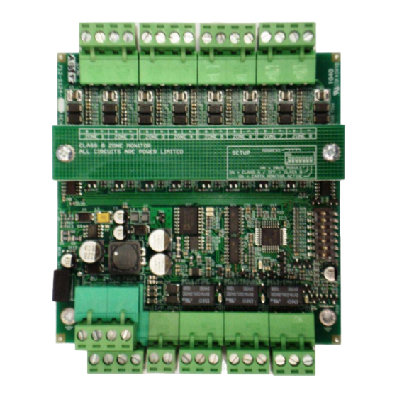
Introduction The AX-CZM (CAX-CZM Canadian ULC version) is Advanced’s conventional zone module that can be monitored and controlled by any ANSI/UL 864 or ULC S527 Listed fire alarm control panel (Host FACP”). The module provides monitoring of up to eigth (8) Class B, with programmable end-of-line, or four (4) Class A conventional zones, and has three Form C relay contacts for signalling an alarm, trouble and, if required, earth/ground fault condition on a per module basis. -
Page 4: Installation
Mounting 2.1.1 AX-CZM Module with Hardware The AX-CZM module is supplied with a terminal designation strip and hardware for mounting in an Advanced AX- 009 enclosure (see figure 2). Note: The AX-009 enclosure can support two (2) AX-CZM modules (see figure 7). -
Page 5: Ax-009 Enclosure Mounting
2.1.2 AX-009 Enclosure Mounting The AX-009 enclosure can be mounted utilizing the provided three mounting holes or it can be mounted to a single or double gang electrical box. Refer to the below diagram for enclosure dimensions. When mounting the AX-009 enclosure to the wall use appropriate hardware to secure properly. -
Page 6: Ax-Czm Module Mounting In Ax-009 Enclosure
2.1.3 AX-CZM Module Mounting in AX-009 Enclosure 1. Screw the four (4) provided hex standoffs on to the four (4) mounting studs of the AX-009 enclosure as indicated below. Figure 4 – AX-CZM Module Standoff Mounting 2. Place the AX-CZM module over the four (4) installed hex standoffs and secure with two (2) screws and two (2) Hex standoffs (see figure 5). - Page 7 REL1 / FIRE REL2 / TROUBLE REL3 / EARTH A PBUS B N / O N / C N / C Figure 6 – Terminal Designation Strip Mounting 4. If a second AX-CZM module is required secure the second AX-CZM module to the right-side mounting studs in the same manner as was explained with the left-side AX-CZM module (see figure 7).
-
Page 8: Dip Switch Programming
DIP Switch Programming Each AX-CZM module has four DIP switch settings for programming module functionalities. The AX-CZM module can be setup as eight (8) Class B or four (4) Class A conventional zones, configured for local earth/ground fault monitoring, if the host panel’s power supply does not provide earth/ground fault detection capabilities, and can be configured for either 3.9K, 4.7K or 6.8K Class B end-of-line (EOL) monitoring. -
Page 9: Ax-Czm Module Operating Modes
AX-CZM Module Operating Modes The AX-CZM module zone circuits are preset to the following operating modes: 2.3.1 Class B Mode of Operation Zone # Latching Input Alarm Verification Short Circuit = Alarm ... -
Page 10: Class A Conventional Zone Wiring
2.4.1 Class A Conventional Zone Wiring 1. Wire out-going conventional zone circuit wiring to “Zone 1, 2, 3 or 4, OUT + and –“. Wire incoming conventional zone circuit wiring to “Zone 1, 2, 3 or 4, IN + and –“(see figure 8). Figure 8 –... -
Page 11: Ax-Czm 24 Vdc Power Wiring
2.4.3 AX-CZM 24 VDC Power Wiring 1. Wire, in conduit, 24 VDC from the Host FACP or an ANSI/UL Listed power supply to terminals 0V and 24V of the AX-CZM module [0V = negative, 24V = positive] (see figure 10). If supplying voltage to multiple AX-CZM modules, wire 0V and 24V to next AX-CZM module. -
Page 12: Ax-Czm Host Panel Monitoring Wiring
2.4.5 AX-CZM Host Panel Monitoring Wiring 1. Wire the host panel monitoring inputs to the Alarm and Trouble contacts of the AX-CZM module. 2. If AX-CZM local earth/ground fault monitoring is required, wire the host panel earth/ground fault monitoring input to the Ground Fault Contact of the AX-CZM module (see figure 12). REL1 / FIRE REL2 / TROUBLE REL3 / EARTH... -
Page 13: Multiple Ax-Czm Module Power And Reset Wiring
2.4.6 Multiple AX-CZM Module Power and Reset Wiring ZONE 1 ZONE 2 ZONE 3 ZONE 4 ZONE 5 ZONE 6 ZONE 7 ZONE 8 ZONE 1 ZONE 2 ZONE 3 ZONE 4 ZONE 5 ZONE 6 ZONE 7 ZONE 8 CLASS B ZONE MONITOR CLASS B ZONE MONITOR ADDRESS... -
Page 14: Typical Host Panel Monitoring/Control Of The Ax-Czm Module
(inverted) loss of 24 VDC power will transfer the trouble contact. End-of-line resistors for the Canadian CAX-CZM must be installed on an Advanced EOL-ASSY (standard single gang end-of-line plate). Preconfigured “Non-Latching” zone circuits (Class B = zones 5 & 6; Class A = zone 4) are not permitted by ANSI/UL864 or ULC S527. -
Page 15: Detector Compatibility
Detector Compatibility Maximum Standby Detector Detector Base Base # of Model Current Type Model Devices / (μA) Circuit GE (ESL - Sentrol) 711U S10A Photoelectric 701E, 701U, 702E, 702U 711UT S10A Photo / Thermal 701E, 701U, 702E, 702U 721U S10A Photoelectric 701E, 701U, 702E, 702U 721UT... - Page 16 301I Ionization 301B 301P Photoelectric 301B 301PT Photo / Thermal 301B 301IL Ionization 301BL 301PL Photoelectric 301BL 301T Photo / Thermal 301BL Fenwal (Kidde-Fenwal) CPD-7021 I1FE1 Duct (Ionization) 70-211002-000 D22FE1 CPD-7021 I1FE1 Ionization 70-201000-001 FEO1A 70-201000-002 FEO2A 70-201000-003 FEO3A 70-201000-005 FEO5A PSD-7125 P5FE1...
-
Page 17: Module Specifications
3.9K, Part Number 855-027-392 End-of-line resistors for the Canadian CAX-CZM must be installed on an Advanced EOL-ASSY (standard single gang end-of-line plate) As our policy is one of constant product improvement the right is therefore reserved to modify product specifications without prior notice www.advancedco.com... - Page 18 Doc Number: 682-040S AFS Revision: First Issued: 2013-mm-dd 100 South Street, Hopkinton, Massachusetts 01748 Tel: (508) 435-9995 Fax: (508) 435-9990 Email: usa@advancedco.com Web: www.advancedco.com www.advancedco.com...
Need help?
Do you have a question about the Axis AX Series and is the answer not in the manual?
Questions and answers