Table of Contents
Advertisement
Quick Links
USER MANUAL
Series 1 G2 - Maritime Multi Display Models
JH 15T17 MMD-xRx-xxxx - 15.0 inch Maritime Multi Display
JH 19T14 MMD-xRx-Sxxx - 19.0 inch Maritime Multi Display (Slim Frame)
JH 19T14 MMD-xRx-xxxx - 19.0 inch Maritime Multi Display
JH 20T17 MMD-xRx-xxxx - 20.1 inch Maritime Multi Display
JH 23T14 MMD-xRx-xxxx - 23.1 inch Maritime Multi Display
User Manual MMD Series 1 G2
Updated: 28 Jun 2021
Created: 363
Please visit www.hattelandtechnology.com for the latest electronic version of this manual.
Doc Id: INB10036-4 (Rev 02)
Approved: 6987
Advertisement
Table of Contents

Related Manuals for EMBRON Hatteland Technology 1 G2 Series

Summary of Contents for EMBRON Hatteland Technology 1 G2 Series
- Page 1 USER MANUAL Series 1 G2 - Maritime Multi Display Models JH 15T17 MMD-xRx-xxxx - 15.0 inch Maritime Multi Display JH 19T14 MMD-xRx-Sxxx - 19.0 inch Maritime Multi Display (Slim Frame) JH 19T14 MMD-xRx-xxxx - 19.0 inch Maritime Multi Display JH 20T17 MMD-xRx-xxxx - 20.1 inch Maritime Multi Display JH 23T14 MMD-xRx-xxxx - 23.1 inch Maritime Multi Display User Manual MMD Series 1 G2 Updated: 28 Jun 2021...
- Page 2 Copyright © 2021 Hatteland Technology AS Eikeskogvegen 52, N-5570 Aksdal, Norway. All rights are reserved by Hatteland Technology AS. This information may not, in whole or in part, be copied, photocopied, reproduced, translated or reduced to any electronic medium or machine- readable form without the prior written consent of Hatteland Technology AS.
-
Page 3: Table Of Contents
Contents Contents ..................3 Contents of package ....................... 6 General .................... 7 IEC62368 policy - Introduction ....................8 About this manual ........................9 About Hatteland Technology ....................9 www.hattelandtechnology.com ....................9 Contact Information ........................ 9 Maritime Multi Display (MMD) - Introduction ................ 10 Product Labeling ........................11 Front Logo Label ....................... - Page 4 Contents Specifications ................69 Specifications - JH 15T17 MMD-xRx-xxxx ................70 Specifications - JH 19T14 MMD-xRx-Sxxx (Slim Frame Model) .......... 71 Specifications - JH 19T14 MMD-xRx-xxxx ................72 Specifications - JH 20T17 MMD-xRx-xxxx ................73 Specifications - JH 23T14 MMD-xRx-xxxx ................74 Technical Drawings ..............
- Page 5 Contents Technical Drawings - JH 15TAP STD-B1 ................98 CRT Adapter - 15” TFT to 17” ................... 98 Technical Drawings - JH 17TAP STD-A1 ................99 17” TFT to 19” Rack Adapter ..................... 99 Technical Drawings - JH 19TAP STD-A1 ................100 CRT Adapter - 19”...
-
Page 6: Contents Of Package
Contents of package Item Description Illustration 1 pcs of Standard DVI Signal Cable. DVI-D 18+1P Male to DVI-D 18+1P Male Single Link - Length 2.0m HA-SDM-2M 1 pcs of Standard VGA Signal Cable. DSUB 15P Male to DSUB 15P Male - Length 2.0m HA-VGA-2M-32 1 pcs of power cable European Type F “Schuko”... -
Page 7: General
General... -
Page 8: Iec62368 Policy - Introduction
IEC62368 policy - Introduction Safety Instructions Please read and understand the material in the manual in its entirety before doing any installation/servicing/upgrades. Personnel who are allowed to do work on the unit is detailed in the “IEC62368 policy for Hatteland Technology product”... -
Page 9: About This Manual
Hatteland Technology AS About this manual The manual contains electrical, mechanical and input/output signal specifications. All specifications in this manual, due to manufacturing, new revisions and approvals, are subject to change without notice. However, the last updated and revision date of this manual are shown both on the frontpage and also in the “Revision History” chapter. This user manual is a standard/general manual that applies to all variations of its product family, i.e. -
Page 10: Maritime Multi Display (Mmd) - Introduction
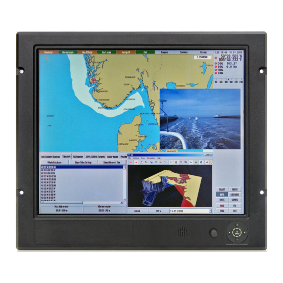
Displays Series 1 - Generation 2 Maritime Multi Display (MMD) - Introduction The Series 1 Generation 2 (G2) Maritime Multi Display (MMD) models are delivered with Multi-power (AC and DC built in) ensuring that they are compatible with all power systems on vessels. The displays will automatically switch to whatever power is connected, making it highly flexible for shipbuilders and system integrators alike. -
Page 11: Product Labeling
Product Labeling Introduction This section details the locations, content details and specifications for factory mounted labels for all currently available standard Hatteland Technology Maritime Multi Display (MMD) - Series 1 Generation 2 models. This information will in most cases also apply for most Customized Models as well, but may differ based on customer requirements, in that case, please refer to the customized User Manual (paper or electronic version, dependent on customer requirements). - Page 12 Product Labeling from rear (and side where needed) with connectors facing down. Actual labels regarding its size and text orientation vs product size is drawn in. Due to space restrictions on selected units, some labels will be rotated 90 degrees to fit properly.
- Page 13 Product Labeling Warranty label covers screw. JH 23T14 MMD-xRx-xxxx Labels placed on rear. IND100077-247...
-
Page 14: Front Logo Label
Product Labeling Warranty Label If you are to perform service on a unit still under warranty, any warranty will be void if this label show signs of removal attempts or damaged by screw driver. This label is located on the back of the product and covers a key screw. This is to aid service departments in determining if there has been any unauthorized service on a unit still under warranty. -
Page 15: Touch Screen Products
Touch Screen products Introduction to products with Touch Screen Both Resistive and Capacitive touch screen solutions are used for our products. Please review specifications found in this manual or our website to find your exact type number and then determine if it uses Resistive or Capacitive. Capacitive Touch screen The glass overlay has a coating that stores the charge deposited over its surface electrically. -
Page 16: Touch Screen Drivers And Documentation
Touch Screen products Touch Screen Drivers and Documentation For products manufactured and delivered with Touch Screen, suitable drivers are available on our website: https://www.hattelandtechnology.com/Series1_MMD_G2 Choose model from the list presented. Once on a specific product, click the “Downloads” tab and scroll to find suitable drivers. -
Page 17: Installation
Installation... -
Page 18: General Installation Recommendations
General Installation Recommendations General Installation Recommendations Installation and mounting 1. Most of our products are intended for various methods of installation or mounting (panel mounting, bracket mounting, ceiling/wall mounting etc.); for details, please see the relevant mechanical drawings. 2. Adequate ventilation is a necessary prerequisite for the life of the product. The air inlet and outlet openings must definitely be kept clear;... - Page 19 General Installation Recommendations General mounting instructions 1. The useful life of the components of all Electronics Units generally decreases with increasing ambient temperature; it is therefore advisable to install such units in air-conditioned rooms. If there are no such facilities these rooms must at least be dry, adequately ventilated and kept at a suitable temperature in order to prevent the formation of condensation inside the display unit.
-
Page 20: Ergonomics
General Installation Recommendations Ergonomics 1. Adjust the unit height so that the top of the screen is at or below eye level. Your eyes should look slightly downwards when viewing the middle of the screen. 2. Adjust screen inclination to allow the angle of gaze to remain at the centre of the screen approximately perpendicular to the line of gaze. -
Page 21: Housing / Terminal Block Connector Overview
General Installation Recommendations Housing / Terminal Block Connector Overview Housing / Terminal Block connectors are available in different sizes (example 2-pin, 4-pin, 5-pin) which plug into the connector area of the unit. They are mounted by factory default and delivered with the unit. The housing / terminal block connectors have steering rails, which ensures that it can not be mounted wrong. - Page 22 General Installation Recommendations Configuring Housing / Terminal Block connectors Below is a brief illustration that might be useful during configuration and installation of such connectors. You will need suitable pre-configured cable(s) and tools to configure the connector(s) and cable(s) that are present in your installation environment.
-
Page 23: Rotary Bracket And Mounting Bracket (15 Inch) Combined Assembling
General Installation Recommendations Rotary Bracket and Mounting Bracket (15 inch) combined assembling Illustration shows “Mounting Bracket JH 15TBR STD-A1” and “Rotary Bracket JH 15TRO STD-A1” combined. The brackets are available separately and are delivered in parts. Some disassembly/assembly is required. Use the provided screws/bolts/nuts included in the package. -
Page 24: Rotary Bracket And Mounting Bracket - Assembling/Finalization
General Installation Recommendations Rotary Bracket and Mounting Bracket - assembling/finalization Illustration shows Mounting Bracket “JH MMDBR STD-A1” / “JH 23TBR T01” and “Rotary Bracket JH MMDRO STD-A1” combined and not combined. The brackets are available separately and may be delivered in parts. Some disassembly/assembly is required. Use the provided screws/ bolts/nuts included in the package. - Page 25 General Installation Recommendations JH MMDBR STD-A1 Hatteland Technology AS Eikeskogvegen 52 JH 23TBR T01 N-5570 Aksdal 23” Hatteland Technology AS Eikeskogvegen 52 N-5570 Aksdal Installation IND100078-26 Hatteland Technology AS Eikeskogvegen 52 N-5570 Aksdal...
-
Page 26: Physical Connections
Physical Connections Introduction: The Maritime Multi Display Series 1 - Generation 2 (G2) has 4 main configurations regarding the connection area. Below are the types of design you may encounter based on model and options chosen. The main physical differences are marked in red circle. - Page 27 Physical Connections Connector Marking: All Maritime Multi Display Series 1 - Generation 2 (G2) units has clear silk printed symbols and text illustrating the connector function and type. Factory options are marked with dashed border on slik print. Example of Connection area silk print and location (19 inch illustrated below) Cable Tension To reduce tension on the cables you connect, secure them with a cable tie to the chassis hinges as illustrated.
- Page 28 Physical Connections 1 x RS-232 COM I/O: This D-SUB 9P connector (female) provides additional functionality for the unit. The Serial Remote Control features a RS-232 (non-isolated) interface for controlling internal parameters like brightness. You can access most of the parameters available in the OSD menu and with special commands control the unit externally. This COM can also be used to upgrade the firmware for the graphic controller inside the unit which is available on request and through service channels (for qualified personnell only).
- Page 29 Physical Connections 2 x DVI-I IN: Connect your DVI cable to any of the two DVI-I 29p connector (female). Secure your DVI cable to the hex spacers provided on the unit and make sure you do not bend any of the pins inside the connector. Connect the other end of the cable to the DVI connector on your equipment and secure it.
- Page 30 This page left intentionally blank...
-
Page 31: Operation
Operation... -
Page 32: User Controls
User Controls USER CONTROLS OVERVIEW The units are available in two different factory user control configurations as illustrated below. Speaker/Buzzer Potmeter Keypad #1: Potmeter & buzzer (introduced Q4 2008) including keypad controls with its Status LED Ring. Brightness for the unit is adjusted by using the potmeter. The tactile keypad control provide access to the configuration menu and Direct Access / Hotkeys functionality. - Page 33 User Controls KEYPAD FUNCTIONALITY Up (+) button Power / Menu button Right / Hotkey button Push Buttons Left / Hotkey button +Direct Access / Hotkeys Status LED Ring Down (-) button MENU function as: Power On/Off & On Screen Display (OSD) menu access. LEFT (◄) function as: Direct Access / Hotkey, exit the current function and navigate to the previous OSD menu.
-
Page 34: Status Led Overview
Status LED Overview Status LED Overview The unit features a multi purpose indicator LED status ring which through different patterns. Realtime activity gives back the status of the signal detected, power on/off, calibration, menu activity and more. The LEDs are multicolored which either illuminate green or red, based on the activity. OFF (No power connected) OFF (Standby, power detected) ON (Signal Search) -
Page 35: On Screen Display (Osd) Menu Introduction
OSD Menu Overview On Screen Display (OSD) Menu Introduction The OSD menu consists of main menus and submenus which are very easy to navigate through. All functions are explained in-depth later in this user manual. Prior to using the OSD menu, you should be sure to familiarize yourself with how to physically access the menu, how to navigate up/down/left/right, how to modify values, exiting menus and more. -
Page 36: Osd Keycode / Osd Lock Mode
OSD Menu Overview OSD Keycode / OSD Lock Mode During use, a small requester may pop-up on screen asking you for a “Key Code”. This is a safety feature (due to ECDIS Compliance) that might be predefined in your setup. To quickly understand how to enter a code, navigate and finally access the underlying main menu, simply follow the illustration below. -
Page 37: Osd "Basic", "Advanced" & "Service" Menu Modes
OSD Menu Overview OSD “Basic”, “Advanced” & “Service” Menu modes Three OSD Modes are available. The “Basic” Menu mode offers easy and clear access to most commonly used functions. The “Advanced” Menu mode offers a more advanced menu with technical information and is suited for more technical minded users and the “Service”... -
Page 38: Osd Menu Structure
OSD Menu Overview OSD Menu Structure In this table all functions within menus and their submenus are shown. Functions that begins with an asterix (*) and bold/red font color style indicates this function/menu is only available during “Advanced” menu mode or during Video CVBS fullscreen. -
Page 39: Color Mode Settings
OSD Menu Overview Color Mode Settings Level 1 (Main Menu) Level 2 Level 3 Level 4 Level 5 Color Mode Settings > < Exit Color Temperature > 9300K, 8000K, 6500K > (Automatic Action) User > < Exit Red > (Slider Bar 0~255) Green >... -
Page 40: Osd Miscellaneous
OSD Menu Overview OSD Miscellaneous Level 1 (Main Menu) Level 2 Level 3 Level 4 Level 5 OSD Miscellaneous > < Exit OSD Position > < Exit OSD H. Position > (Slider Bar 0~255) OSD V. Position > (Slider Bar 0~255) Language >... -
Page 41: Management Settings
OSD Menu Overview Management Settings Level 1 (Main Menu) Level 2 Level 3 Level 4 Level 5 Management Settings > < Exit * Graphic Scaling > < Exit Graphic Scaling > Full Screen, Fill to Aspect Ratio, One To One Zoom >... -
Page 42: Service Settings
OSD Menu Overview Service Settings Level 1 (Main Menu) Level 2 Level 3 Level 4 Level 5 Service Settings > < Exit Video Scaler Firmware Ver > (Text Displayed) uC Firmware > (Text Displayed) Elapsed Time > (Text Displayed) Current Temp > (Text Displayed) *Fault Status >... -
Page 43: On Screen Display (Osd) Menu Functions
OSD Menu Functions On Screen Display (OSD) Menu Functions The following section covers all possible settings that the user can (in a certain mode) encounter or needs to adjust via easy understandable menus, text and navigation. For simpler reading the menu choice "Exit" has been left out of description in this chapter intentionally. - Page 44 OSD Menu Functions Input Source Settings - DVI-I1 Mode |---2--- This OSD setting item is used to select the DVI-I1 port operating mode. Settings as follows: DVI Mode = The port is locked to DVI-D mode, only accepting digital input. "Analog RGB1"...
- Page 45 OSD Menu Functions Input Source Settings - Rename Source |---2--- By factory default, every signal source input are named based on it’s signal property as described in the previous functions, but with the rename source function you can rename these into more understandable descriptions like;...
- Page 46 OSD Menu Functions Image Settings Lets you configure various visual preferences for any signal. The contents of these submenu are listed below. Image Settings - Auto Position |---2--- Will automatically fit the currently displayed full screen signal and center it based on the active area of the TFT display.
- Page 47 OSD Menu Functions Image Settings - Hue *Available in "Advanced" only + Video Fullscreen |---2--- Allows you to adjust/shift the main color properties of all Red, Green, Blue and Yellow (unique hues) values. This can be useful for certain Composite Video sources (no effect on DVI/DP/VGA signals) whose output may have shifted or seems to be "out of phase", where for instance blue seems more dominant than green, red and yellow-ish colors.
- Page 48 OSD Menu Functions Image Settings - Display - Clock |--------3-------- Adjust the horizontal frequency (clock) of the analog signal to improve visibility of the entire image. When it is adjusted, you will notice that the image will appear to be stretched and might in some situations start to flicker/scroll, at which point you must reverse the last adjustment to stop it from flickering/scrolling anymore.
- Page 49 OSD Menu Functions Image Settings - Video Setup *Available when Video Fullscreen only |---2--- Provides submenus where the following settings for Composite video signals are available: Image Settings - Video Setup - Main MADI mode |--------3-------- Motion Adaptive De-Interlacing. Motion adaptive de-interlacing is a pixel-based two-phase process.
- Page 50 OSD Menu Functions Image Settings - Video Setup - Noise Reduction - MPEG NR Mode |-------------4------------- MPEG NR (the generic coding of moving pictures and associated audio information) can be set to either "ON" or "OFF". This function will try to reduce noise as result from compressed/formatted MPEG video streams.
- Page 51 OSD Menu Functions Color Mode Settings Lets you adjust the color temperature (Kelvin degrees) of the image. This applies to the Main Source signal. Window overlays (PIP/PBP) and the OSD Menu overlay will be unaffected. Lower values make the image appear warmer, while higher values will make it appear cooler.
- Page 52 OSD Menu Functions Multi-PIP Settings Lets you adjust how the Picture-in-Picture (PIP) or Picture-by-Picture (PBP) display modes are set up. The default position of the rectangle is set to the upper left corner of the Active Display area. Note that this requires a valid incoming signal to be present in any of the "DVI", "DisplayPort", "VGA"...
- Page 53 OSD Menu Functions Multi-PIP Settings - PIP Display *Available only when PIP Mode on |---2--- When PIP Child mode is active, the size and position of the rectangle displaying the Secondary Source can be adjusted via the submenus below. Secondary Source needs to be a valid signal source.
- Page 54 OSD Menu Functions Multi-PIP Settings - PIP Picture |---2--- When PIP mode is active, the picture appearance of the Secondary Source can be adjusted via the following settings: Settings as follows: "Brightness" = Adjust the black level (brightness) of the Secondary Source, values from 0 to 255.
- Page 55 OSD Menu Functions OSD Miscellaneous Allows you to customize the visual appearance of the On Screen Display (OSD) menu, such as; position, transparency, time-out, assign hot keys, define access modes and save, load and recall favourite settings and more. The contents of these submenus are listed below. OSD Miscellaneous - OSD Position |---2---...
- Page 56 OSD Menu Functions OSD Miscellaneous - Preset Save - Save |--------3-------- Allows you to save current state of all function and values to user defined presets. The contents of the submenu is listed below. Settings as follows: "User 1" = Save all OSD settings to User 1 slot. "User 2"...
- Page 57 OSD Menu Functions OSD Miscellaneous - OSD Mode |---2--- Configuring the OSD Menu access based on most common functions to service/troubleshooting. Settings as follows: “Basic” = A few functions is not visible/available in this state. For most uses this is the preferred setting and are safe for the display functionality and continuous trusted operation on the unit.
- Page 58 OSD Menu Functions OSD Miscellaneous - Hot Key Assignment *Available in "Advanced/Service" mode only |---2--- Assign a commonly used OSD menu function to the available touch enabled Hot Keys which are located on the front of unit (user controls). The following functions are available to assign and most of them have a negative and positive counting logic.
- Page 59 OSD Menu Functions OSD Miscellaneous - OSD Key Outdoor *Available in "Advanced/Service" mode only |---2--- To prevent accidental activation of Glass Display Control™ (GDC) touch functions, you can add an extra layer of security on how "sensitve" the touch detection operates. This applies for "MENU", "(-) Brilliance (+)"...
- Page 60 OSD Menu Functions Management Settings Allows you to adjust overall settings for interaction/communication for the unit, such as scaling, zoom, timing of signals, sensitivity for the touch control, VGA filter and Serial/Ethernet communication and more. The contents of these submenus are listed below. Management Settings - Graphic Scaling *Available in "Advanced"...
- Page 61 OSD Menu Functions Management Settings - Graphic Scaling - Horizont Stretch |--------3-------- All stretching will performed from center of active display area and outwards in one direction. Settings as follows: "Horizont Stretch" = Zoom/stretch current full screen signal in Horizontal direction only (left and right).
- Page 62 OSD Menu Functions Management Settings - Unknown Timing Search *Available in "Advanced" mode only |---2--- Use this if you are unable to find or detect the incoming full screen signal automatically (applies for Analog VGA and CVBS video signals only. A PIP or PBP configured signal is not supported). It may be a customized signal regarding resolution and refresh frequency.
- Page 63 OSD Menu Functions Management Settings - Unknown Timing Search - Save Timing |--------3-------- The current "Timing Table Data" that is currently visible in the "Blind Mode" or via the "Auto Mode" functions may now be saved to a user defined slot. Available save slots from 1 to 8. Saving "Time Table Data"...
- Page 64 OSD Menu Functions Management Settings - Communication *Available in "Advanced" mode only |---2--- The unit allows for remote control (adjust brightness for example) and/or accessing internal information about the unit such as typenumber, serial number and more. To setup this feature, you first need to configure the Serial, Ethernet or USB protocol properly to match your external equipment specifications.
- Page 65 OSD Menu Functions Management Settings - Power Plan *Available in "Advanced" mode only |---2--- This setting will allow you to control the power mode of USB/VGA out and Ethernet port in Power off mode. Settings as follows for "VGA Out/USB in Off Mode": "Enable"...
- Page 66 OSD Menu Functions Management Settings - External Power Button *Available in "Advanced" mode only |---2--- This setting will allow you to manually enable the use of an external power button to turn off the Display unit. Please review the Pinout Assignments (Potmeter Control 9-pin DSUB MALE Connector) for connectivity.
- Page 67 OSD Menu Functions Service Settings Will show various technical and unit related information, such as; Firmware versions, Elapsed Time, Internal Temperature, Fault Status and activation for the internal Test Pattern image useful for trouble- shooting. Some of these functions are static information while others are accessible. Whenever you are in contact with helpdesk or service, they might require you to read back some of these values in order to precisely pinpoint any problem/question you should have with the unit or its functionality.
- Page 68 OSD Menu Functions Service Settings - Test Pattern |---2--- Will show the internal test pattern with greyscales, colors and raster patterned boxes to check for deviations in the TFT panel/display controller behaviour. It is independent of any current resolution or specifications found in the signal inputs. The test pattern is generated internally in the display controller and is sent 1:1 directly to the TFT panel.
-
Page 69: Specifications
Specifications... -
Page 70: Specifications - Jh 15T17 Mmd-Xrx-Xxxx
Specifications - JH 15T17 MMD-xRx-xxxx SPECIFICATIONS Note: All specifi cations are subject to change without prior notice! Please visit www.hattelandtechnology.com for the latest electronic version. All specifications are subject to change without prior notice! TFT Technology: Physical Considerations: • High Quality TFT with LED Backlight Technology •... -
Page 71: Specifications - Jh 19T14 Mmd-Xrx-Sxxx (Slim Frame Model)
Specifications - JH 19T14 MMD-xRx-Sxxx (Slim Frame Model) SPECIFICATIONS Note: All specifi cations are subject to change without prior notice! Please visit www.hattelandtechnology.com for the latest electronic version. All specifications are subject to change without prior notice! Physical Considerations: TFT Technology: •... -
Page 72: Specifications - Jh 19T14 Mmd-Xrx-Xxxx
Specifications - JH 19T14 MMD-xRx-xxxx SPECIFICATIONS Note: All specifi cations are subject to change without prior notice! Please visit www.hattelandtechnology.com for the latest electronic version. All specifications are subject to change without prior notice! Physical Considerations: TFT Technology: • W:483.00 [19.02''] x H:444.00 [17.48''] x D:82.00 [3.23''] mm [inch] •... -
Page 73: Specifications - Jh 20T17 Mmd-Xrx-Xxxx
Specifications - JH 20T17 MMD-xRx-xxxx SPECIFICATIONS Note: All specifi cations are subject to change without prior notice! Please visit www.hattelandtechnology.com for the latest electronic version. All specifications are subject to change without prior notice! TFT Technology: Physical Considerations: • High Quality TFT with LED Backlight Technology •... -
Page 74: Specifications - Jh 23T14 Mmd-Xrx-Xxxx
Specifications - JH 23T14 MMD-xRx-xxxx SPECIFICATIONS Note: All specifi cations are subject to change without prior notice! Please visit www.hattelandtechnology.com for the latest electronic version. All specifications are subject to change without prior notice! TFT Technology: Physical Considerations: • High Quality TFT with LED Backlight Technology •... -
Page 75: Technical Drawings
Technical Drawings... -
Page 76: Technical Drawings - Jh 15T17 Mmd-Xrx-Xxxx
Technical Drawings - JH 15T17 MMD-xRx-xxxx IND100132-496... -
Page 77: Technical Drawings - Jh 15T17 Mmd-Xrx-Xxxx
Technical Drawings - JH 15T17 MMD-xRx-xxxx Keypad only model IND100132-509... -
Page 78: Technical Drawings - Jh 19T14 Mmd-Xrx-Sxxx
Technical Drawings - JH 19T14 MMD-xRx-Sxxx Slim Frame Model IND100132-497... -
Page 79: Technical Drawings - Jh 19T14 Mmd-Xrx-Xxxx
Technical Drawings - JH 19T14 MMD-xRx-xxxx IND100132-498... -
Page 80: Technical Drawings - Jh 20T17 Mmd-Xrx-Xxxx
Technical Drawings - JH 20T17 MMD-xRx-xxxx IND100132-499... -
Page 81: Technical Drawings - Jh 23T14 Mmd-Xrx-Xxxx
Technical Drawings - JH 23T14 MMD-xRx-xxxx IND100132-500... - Page 82 This page left intentionally blank...
-
Page 83: Technical Drawings - Accessories
Technical Drawings - Accessories... -
Page 84: Technical Drawings - Jh 15Tsv Std-A1
Technical Drawings - JH 15TSV STD-A1 Sun Visor - 15” IND100132-109... -
Page 85: Technical Drawings - Jh 19Tsv Std-B1
Technical Drawings - JH 19TSV STD-B1 Sun Visor - 19” Slim Frame IND100132-202... -
Page 86: Technical Drawings - Jh 19Tsv Std-A1
Technical Drawings - JH 19TSV STD-A1 Sun Visor - 19” IND100132-67... -
Page 87: Technical Drawings - Jh 20Tsv Std-B1
Technical Drawings - JH 20TSV STD-B1 Sun Visor - 20” IND100132-111... -
Page 88: Technical Drawings - Jh 23Tsv Std-A1
Technical Drawings - JH 23TSV STD-A1 Sun Visor - 23” IND100132-112... -
Page 89: Technical Drawings - Jh 15Tro Std-A1
Technical Drawings - JH 15TRO STD-A1 Rotary Bracket - 15” IND100132-148... -
Page 90: Technical Drawings - Jh Mmdro Std-A1
Technical Drawings - JH MMDRO STD-A1 Rotary Bracket - 17” to 26” IND100132-46... -
Page 91: Technical Drawings - Jh 15Tbr Std-B1
Technical Drawings - JH 15TBR STD-B1 Mounting Bracket - 15” IND100132-167... -
Page 92: Technical Drawings - Jh Mmdbr Std-A1
Technical Drawings - JH MMDBR STD-A1 Mounting Bracket - 17” to 20” IND100132-69... -
Page 93: Technical Drawings - Jh 19Tbr Std-B1
Technical Drawings - JH 19TBR STD-B1 Mounting Bracket - 19” Slim Frame IND100132-255... -
Page 94: Technical Drawings - Jh 19Brd Std-A1
Technical Drawings - JH 19BRD STD-A1 EN60945 Mounting Bracket - 19” IND100132-165... -
Page 95: Technical Drawings - Jh 23Tbr T01-A1
Technical Drawings - JH 23TBR T01-A1 Mounting Bracket - 23” IND100132-129... -
Page 96: Technical Drawings - Jh 23Brd Std-A1
Technical Drawings - JH 23BRD STD-A1 EN60945 Mounting Bracket - 23” IND100132-166... -
Page 97: Technical Drawings - Jh 15Tap Std-A1
Technical Drawings - JH 15TAP STD-A1 19” Rack Adapter - 15” TFT IND100132-43... -
Page 98: Technical Drawings - Jh 15Tap Std-B1
Technical Drawings - JH 15TAP STD-B1 CRT Adapter - 15” TFT to 17” IND100132-137... -
Page 99: Technical Drawings - Jh 17Tap Std-A1
Technical Drawings - JH 17TAP STD-A1 17” TFT to 19” Rack Adapter IND100132-138... -
Page 100: Technical Drawings - Jh 19Tap Std-A1
Technical Drawings - JH 19TAP STD-A1 CRT Adapter - 19” TFT to 21” IND100132-44... -
Page 101: Technical Drawings - Jh 19Tap Std-A2
Technical Drawings - JH 19TAP STD-A2 CRT Adapter - 19” TFT to 20” TFT IND100132-254... -
Page 102: Technical Drawings - Jh 19Tap Std-B1
Technical Drawings - JH 19TAP STD-B1 CRT Adapter (Custom) - 19” TFT to 21” IND100132-187... -
Page 103: Technical Drawings - Jh 15Ved Std-A1
Technical Drawings - JH 15VED STD-A1 VESA Adapter - 15” IND100132-113... -
Page 104: Technical Drawings - Jh 19Ved Std-A1
Technical Drawings - JH 19VED STD-A1 VESA Adapter - 19” IND100132-45... -
Page 105: Technical Drawings - Jh 19Ved Std-B1
Technical Drawings - JH 19VED STD-B1 VESA Adapter - 19” Slim Frame IND100132-193... -
Page 106: Technical Drawings - Jh 20Ved Std-A1
Technical Drawings - JH 20VED STD-A1 VESA Adapter - 20” IND100132-115... -
Page 107: Technical Drawings - Jh 23Ved Std-A1
Technical Drawings - JH 23VED STD-A1 VESA Adapter - 23” IND100132-116... -
Page 108: Technical Drawings - Jh 15Twc Std-A1
Technical Drawings - JH 15TWC STD-A1 Water Cover - 15” IND100132-117... -
Page 109: Technical Drawings - Jh 19Twc Std-B1
Technical Drawings - JH 19TWC STD-B1 Water Cover (HW01) - 19” IND100132-136... -
Page 110: Technical Drawings - Jh 19Twc Std-C1
Technical Drawings - JH 19TWC STD-C1 Water Cover - 19” Slim Frame IND100132-195... -
Page 111: Technical Drawings - Jh 20Twc Std-B1
Technical Drawings - JH 20TWC STD-B1 Water Cover - 20” IND100132-119... -
Page 112: Technical Drawings - Jh 23Twc Std-A1
Technical Drawings - JH 23TWC STD-A1 Water Cover - 23” IND100132-120... -
Page 113: Appendixes
Appendixes... -
Page 114: Pinout Assignments
Pinout Assignments Connectors illustrated here are either standard by factory default or may be available (through factory customization). Note that some combinations may not be possible due to space restrictions. List also valid for customized models. All pin out assignments are seen from users Point of View (POV) while looking straight at the connector. Please review the dedicated datasheet or technical drawings for your actual unit to identify and determine the presence of desired connector. - Page 115 Pinout Assignments Potentiometer Control, 9-pin DSUB Male External Power ON/OFF Control, 9-pin DSUB Male Warning: Do not connect or 4 3 2 1 Warning: Do not connect or 4 3 2 1 disconnect cables/connectors disconnect cables/connectors to this connector while the to this connector while the Display unit is powered on.
- Page 116 Pinout Assignments 10-pin RS-422 / RS-485 Module Serial COM RS-232 non-isolated, 9-pin DSUB Male “RS-422/RS-485 SCOM + Buzzer” 1 2 3 4 5 (Internal Buzzer can be controlled externally) 2 4 6 8 10 1 3 5 7 9 PIN 01 DCD Data Carrier Detect PIN 02 RxD Receive Data...
-
Page 117: Iec62368 Policy For Hatteland Technology Products
IEC62368 policy for Hatteland Technology products Introduction According to the requirements of EN 62368-1:2014. The tables below refers to the policies for opening, servicing and installation of the unit(s) referred to in this manual. This equipment is designed to be used as a fixed installation and to be sold through special sales channels for professional use. - Page 118 IEC62368 policy for Hatteland Technology products Authority Description Children This equipment is not suitable for use in locations where children are likely to be present. Ordinary person/ Not allowed to open unit. Sailor/End-User Not allowed to install the unit. Not allowed to terminate/connect cables to the unit. Instructed person Allowed to open hatches/latches which does not require tools, such as Disktrays.
-
Page 119: Basic Trouble-Shooting
Basic Trouble-shooting GENERAL ISSUES FOR TFT PANEL BASED PRODUCTS Note: Applies for a range of various products. This is only meant as a general guide. O PICTURE / LED BEHAVIOUR: If there is no light at all in the LED at the FRONT, check power cables. If the LED in front is green, then check if the brightness is set/adjusted to max brightness. -
Page 120: Declaration Of Conformity
Declaration of Conformity We, manufacturer, Hatteland Technology AS, Eikeskogvegen 52, N-5570 Aksdal, Norway declare under our sole responsibility that the JH MMD, JH MMC, JH STD, JH MIL, HM NMD, HM MIL, HM CMD, HT STD, HD MMD, HD MVD, HM MMD, HM XRD, HM RMD, HT MMC, HD MMC and HT/HM (computers) product ranges is in conformity with the following standards in accordance with the EMC Directive. -
Page 121: Return Of Goods Information
Return Of Goods Information Return of goods: (Applies not to warranty/normal service/repair of products) Hatteland Technology referenced as “manufacturer” in this document. Before returning goods, please contact your system supplier before sending anything directly to manufacturer. When you return products after loan, test, evaluation or products subject for credit, you must ensure that all accessories received from our warehouse are returned. -
Page 122: General Terms And Conditions
General Terms and Conditions As of January 2015, Hatteland Technology AS’ “Terms of Sales and Delivery” and “Warranty Terms” have been substituted by the updated ”General terms and conditions for sale of goods and performance of additional services” (the “General Terms and Conditions”). Further, from January 2015 onward, the previous “Terms of Sales and Delivery”... -
Page 123: Pixel Defect Policy
Pixel Defect Policy PIXEL DEFECT POLICY Dot-defects (Bright or dark spots on the panel) Due to the effect that dot failures are part of the TFT technology such failure occurrence cannot be prevented basically. Even though dot defects usually occur during production process, new defects can appear within the lifespan of a TFT display. Neither the production at LCD-supplier nor the use of an LCD-Monitor after shipment can be influenced by Hatteland Technology. -
Page 124: Parts And Recycling
Parts and Recycling Rev 02 - 20 May 2021 Parts in Displays and Panel Computers, and how to recycle Part Where to dispose of parts TFT Panel Electrical waste Optically bonded units: the TFT Panel, Glass Metal waste Glass and frame is to be disposed of as Electrical waste. -
Page 125: Notes
Notes General Notes: - The unit is tested according to IEC 60945 4th (EN 60945:2002), 4.4, equipment category b) “protected from the weather (formerly class B)”. - Use of brightness and push buttons may inhibit visibility of information at night. Manufacturing Note - 28 Jun 2021: All Series 1 Generation 2 units manufactured from 1st of January 2021 to and including June 25th, 2021, had an incorrect polarity definition (silk print marking on terminal plate) that was reversed indicating originally “+ 24V DC -”... -
Page 126: Revision History
Revision History Rev. Date Notes 00_01 11 Dec 2020 First release for internal review 00_02 09 Mar 2021 Updated with latest information 25 Jun 2021 Updated with latest information, release v1 final for internet 28 Jun 2021 Added note for “DC Power Input - incorrect polarity marking”, page 125 (ref: QAR/151793) Appendix IND100077-246... - Page 127 Revision History Appendix IND100077-246...
- Page 128 Hatteland Technology AS | www.hattelandtechnology.com | Enterprise no: NO974533146...
Need help?
Do you have a question about the Hatteland Technology 1 G2 Series and is the answer not in the manual?
Questions and answers