
Related Manuals for COMEM DTI


Summary of Contents for COMEM DTI
- Page 1 TRANSFORMER COMPONENTS Temperature monitoring unit DTI and eDTI Instruction manual...
-
Page 2: Table Of Contents
TEMPERATURE MONITORING UNIT DTI AND EDTI Content index Safety ..........4 DTI and eDTI ........5 Electrical diagram .......7 Front panel description .......8 Programming of the device ....9 Modality of tripping and restore ..15 Diagnostic ........16 Visualization of the maximum measured temperature .....17 Visualization of the channels with the higher temperature .....17... -
Page 3: Safety
All relevant fire protection regulation must application only. be strictly observed. For safety matters, please avoid any unauthorized and improperly works. CAUTION The temperature control unit DTI/eDTI must not be installed near sources of electromagnetic interference. -
Page 4: Dti And Edti
DTI and eDTI Product description The Temperature monitoring device DTI/eDTI is used in resin or dry type transfor- mers and can also be easily adapted for use in oil transformers. The DTI/eDTI uses PT100 temperature probes for a constant monitoring of tran- sformer temperatures. - Page 5 DTI and eDTI Connection of the temperature sensors For the connection of the sensor RTD PT100 it’s necessary to follow the indica- tion of the wiring diagram of this manual: pay attention to not invert the position between the conductors with red insulator and the conductor with white insulator.
-
Page 6: Electrical Diagram
TEMPERATURE MONITORING UNIT DTI AND EDTI Electrical diagram View rear panel of the instrument with terminals for the connections... -
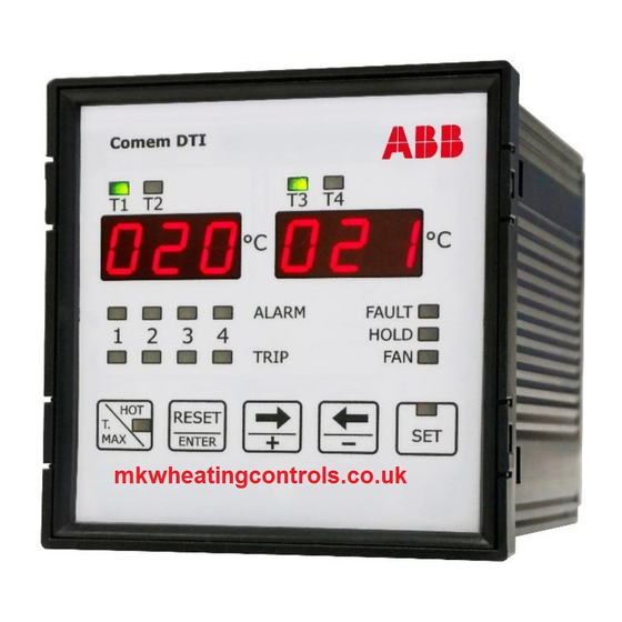
Page 7: Front Panel Description
HOLD HOLD TRIP TRIP RESET RESET ENTER ENTER Modbus RTU / 4-20mA Front panel description eDTI T1 T2 T3 T4 T1 T2 T3 T4 0 3 3 0 3 3 °C °C °C °C ALARM FAULT ALARM FAULT HOLD HOLD TRIP TRIP RESET... -
Page 8: Programming Of The Device
TEMPERATURE MONITORING UNIT DTI AND EDTI Programming of the device When the device is switched on, on the display will flash the index of the internal software: later the device starts to display the temperature read on the measured input. - Page 9 Programming of the device Selection of the number of active inputs It is possible to select the number of activated inputs. It’s possible to choose between 3 and 4 inputs enabled; if there are 3 inputs enabled the T4 display remain off.
- Page 10 TEMPERATURE MONITORING UNIT DTI AND EDTI Programming of the device Selection of the threshold of switch-on and switch-off ventilation It is possible to program the threshold for enabling and disabling the ventilation. • Selection the threshold for disabling ventilation The FAN LED is on, with fixed light indicates this phase of programming.
- Page 11 Programming of the device Selection of the baud rate NOTE This setting is significant only for eDTI model. This setting is indicated on displays with: • BDR on T1-T2 display • value to set on T3-T4 display. With ← and → keys select the baud rate It’s possible to choose between the following values: 2,4 - 4,8 - 9,6 - 19,2 kbps.
- Page 12 TEMPERATURE MONITORING UNIT DTI AND EDTI Programming of the device Selection of the linked channel with the analogue output NOTE This setting is significant only for eDTI model. This setting is indicated on displays with: • AN on T1-T2 display •...
- Page 13 Programming of the device Configuration diagnostic probes This function allows to enable or to disable the control on the probes. This fun- ctionality controls the variation of the temperature in a defined time. A flag raise if this variation is higher than a set value. FDC setting T1-T2 display T3-T4 display...
-
Page 14: Modality Of Tripping And Restore
TEMPERATURE MONITORING UNIT DTI AND EDTI Modality of tripping and restore Alarm On the relative channel, if the threshold value set is exceeded of +1°C, after 5 seconds the ALARM relay is energized and the ALARM led is. The alarm rearm (relay de-energized and the involved LED off) occurs when the temperature goes down of 2°C respect at the threshold value set. -
Page 15: Diagnostic
Diagnostic The device is provided of the thermic probes diagnostic function. The condition controlled on the measured input are: • Probe PT100 interrupted: signalling on the display the message O P E (open). • Probe in short circuit: signalling on the display the message S H R (short circuit). -
Page 16: Visualization Of The Maximum Measured Temperature
TEMPERATURE MONITORING UNIT DTI AND EDTI Visualization of the maximum measured temperature On the relative channel, if the threshold value set is exceeded of +1°C, after 5 se- conds the ALARM relay is energized and the ALARM led is. The alarm rearm (relay de-energized and the involved LED off) occurs when the temperature goes down of 2°C respect at the threshold value set. -
Page 17: Technical Features
• check that there are no breakages If damage is found, please contact COMEM and provide the shipping data together with the serial number of the unit. The temperature monitoring device DTI/eDTI must be stored in a dry place at temperatures as indicated above. -
Page 18: Appendix A: Modbus Address
TEMPERATURE MONITORING UNIT DTI AND EDTI Appendix A: MODBUS Address Register address Operations Description Notes Operation for monitoring 0x280 CH1 Instantaneous Temperature [°C] 0x281 CH2 Instantaneous Temperature [°C] 0x282 CH3 Instantaneous Temperature [°C] 0x283 CH4 Instantaneous Temperature [°C] 0x288 CH1 Maximum Temperature [°C] 0x289 CH2 Maximum Temperature [°C]... -
Page 19: Dimensions
eDTI T1 T2 T3 T4 T1 T2 T3 T4 °C °C °C °C Dimensions ALARM FAULT ALARM FAULT HOLD HOLD TRIP TRIP RESET RESET ENTER ENTER Modbus RTU / 4-20mA eDTI T1 T2 T3 T4 T1 T2 T3 T4 0 3 3 0 3 3 °C °C... - Page 20 This installation manual contains essential information for the user required to install & operate the product. In case you need any further information, contact us at customerservice@it.comem.com. Copyright 2021 COMEM. All rights reserved Manual-05-2021...
Need help?
Do you have a question about the DTI and is the answer not in the manual?
Questions and answers