Table of Contents
Advertisement
Quick Links
SEQUENCER WITH
DIFFERENTIAL PRESSURE
SWITCH
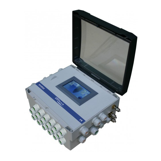
Outputs SV AC version
Not ATEX version
ATEX version
ABS Box
PC Box
PLACE GUTENBERG - 59175 TEMPLEMARS (France)
Tel: +33(0)3 20 60 49 49 - Fax: +33(0)3 20 95 59 62
Email:
contact@sefram.eu
Web:
www.sefram.eu
Technical brochure
FI 72.0483.0720E
Page 1 sur 43
Advertisement
Table of Contents

Related Manuals for SEFRAM SET100DP

Summary of Contents for SEFRAM SET100DP
- Page 1 Not ATEX version ATEX version ABS Box PC Box PLACE GUTENBERG - 59175 TEMPLEMARS (France) Tel: +33(0)3 20 60 49 49 - Fax: +33(0)3 20 95 59 62 Email: contact@sefram.eu Web: www.sefram.eu Technical brochure FI 72.0483.0720E Page 1 sur 43...
-
Page 2: Table Of Contents
DIFFERENTIAL PRESSURE SWITCH SOMMAIRE : DESCRIPTION : Page The SET100DP is an adjustable device for control and full automatization of declogging equipment, whose declogging is - DESCRIPTION done by pressured air injections. - CHARACTERISTICS It can perform various functions: declogging sequence, filter load... -
Page 3: Characteristics
SEQUENCER WITH DIFFERENTIAL PRESSURE SWITCH CARACTERISTIQUES : - Supply voltage (nominal voltage) : Depending version: 10 % 50-60 Hz 115V/230V 10 % 50-60 Hz 24V/48V - Consumption (nominal current) maxi : 5VA + SV consumption - Protection : By fuses 5x20mm (see table 1) - Tension électrovannes: According supply voltage (see table 1) - Page 4 SEQUENCER WITH DIFFERENTIAL PRESSURE SWITCH LOAD LOSS DP MEASURE : - Scale 0-500 daPa Display accuracy : 1 daPa - maxi pressure 1400 mbar - accuracy 1.5% on sensor maxi scale (100 mbar) → from 0 to 50°C this accuracy takes into consideration linearity, hysteresis, temperature and repetitivity effects 0% to 95% RH –...
-
Page 5: Dimensions And Mounting
SEQUENCER WITH DIFFERENTIAL PRESSURE SWITCH DIMENSIONS AND MOUNTING MOUNTING (not ATEX version) : Main Box / front side, right side and left side : dP + pressure connection (dirty air side) Connection for 6/8mm tube dP - pressure connection (clean air side) Connection for 6/8mm tube Compressed air pressure connection Connection for 4/6mm tube... - Page 6 SEQUENCER WITH DIFFERENTIAL PRESSURE SWITCH Main Box ou SV Extension Box / undersize of the box: Individual cables version (1 common + ground per SV) 18xISO16 Multiconductors cables version (3 common + 3 ground for 3x6 EV) 3xISO20b Multiconductors cables version if version with possibility of connection of two SV...
- Page 7 SEQUENCER WITH DIFFERENTIAL PRESSURE SWITCH SV extension box : ISO20 : supply ISO16b : extension com input ISO16b : extension com output On the underside of the box: SV connection area see previous page Main box or SV extension box / behind side of the box: Technical brochure FI 72.0483.0720E...
- Page 8 SEQUENCER WITH DIFFERENTIAL PRESSURE SWITCH DIMENSIONS AND MOUNTING (ATEX version) : Only version SV Pmax=25VA Main Box / front side, right side and left side : On the underside of the box: SV connection area see next page supply extension com CDM com customer com dP - pressure connection...
- Page 9 SEQUENCER WITH DIFFERENTIAL PRESSURE SWITCH Main Box or extension SV box / undersize of the box: Individual cables version (1 common + ground per SV) 18xISO16 Multiconductors cables version (3 common + 3 ground for 3x6 EV) 3xISO20b Clamping capacity of the cable glands: Identify the cable glands used by the markings on the cable glands and refer to the tightening capacity of the cable glands specified in the instructions of the cable gland manufacturer (document supplied with brochure + ATEX instructions).
- Page 10 SEQUENCER WITH DIFFERENTIAL PRESSURE SWITCH SV extension box : front side, right side and left side (note : undersize of the box → same as main box) supply extension com input extension com output Technical brochure FI 72.0483.0720E Page 10 sur 43...
-
Page 11: Protection
SEQUENCER WITH DIFFERENTIAL PRESSURE SWITCH PROTECTION : Table 1: Supply Voltage / Solenoid Valves Voltage / Fuses If version, Pmax SV : 25VA Supply voltage 230VAC 115VAC Solenoides valves voltage 230VAC 48VAC 24VAC 115VAC 48VAC 24VAC fuse F1 caliber fuse F2 caliber fuse F3 caliber Supply voltage 48VAC... - Page 12 SEQUENCER WITH DIFFERENTIAL PRESSURE SWITCH VOLTAGE CHOICE : It is possible according to the version of the device to set differently the supply voltage and the solenoid valves voltage of that made by default in factory answering the ordered version. Warning: the device must be switched off. Notes: The supply choices "115V / 230V"...
- Page 13 SEQUENCER WITH DIFFERENTIAL PRESSURE SWITCH Jumper on : S4 / S5 / S6 230VAC / 24VAC 230VAC / 48VAC Nothing on : S1 / S2 / S3 Jumper on : S3 / S5 / S6 115VAC / 24VAC 115VAC / 48VAC Nothing on : S1 / S2 / S4 WARNING : a modification of the supply voltage and/or the solenoid valves voltage requires to...
-
Page 14: Connections
SEQUENCER WITH DIFFERENTIAL PRESSURE SWITCH CONNECTIONS: Connections must be done when power off Connections terminals are reachable after dismounting the front panel of the box. According to configuration of the device, some terminals may not be included. Cable strings will be flexible and will have a section between 0.5 and 1.5 mm Power supply of the device: The power supply for the device is connected in the upper part to the left of the board : Supply... - Page 15 SEQUENCER WITH DIFFERENTIAL PRESSURE SWITCH AON inputs / relay outputs / 4-20mA outputs: These connections are located on the right side of the board: compressed air 4-20mA output for recorder, indicator, etc. max load : 500 ohms 4-20mA output for recorder, indicator, etc.
- Page 16 SEQUENCER WITH DIFFERENTIAL PRESSURE SWITCH SV outputs : These connections are located at the bottom and center of the board: If version up to 18 SV by individual cable (1 common + ground per SV): Connection of the outputs Solenoid valves 1 to 18 18x common SV 18x ground SV If version up to 18 SV by multiconductors cable (1 common + ground for 6 SV):...
- Page 17 SEQUENCER WITH DIFFERENTIAL PRESSURE SWITCH If version up to 18 SV outputs by multiconductors cables And if version with possibility of connection of two SV per output if version pmax SV: 40VA (6 common + 6 ground for 6x6 SV) : 6x common SV 6x ground SV Connection of the outputs solenoid valves 1 to 18...
- Page 18 SEQUENCER WITH DIFFERENTIAL PRESSURE SWITCH Wiring between main box and SV extension boxes: Up to 8 EV extension boxes can be connected to the main box to expand the number of solenoid valves. Each extension box is numbered from 1 to 8 thanks to a rotary switch encoder. On each extension: place the arrow of the rotary switch encoder in front of the associated number (1 to 8).
-
Page 19: User Interface
SEQUENCER WITH DIFFERENTIAL PRESSURE SWITCH USER INTERFACE : The user interface is made with the touchscreen on the front of the cabinet. When the power is turned on, the company logo is displayed for 3 seconds and the main page is displayed. To activate a function or access the setting of a parameter: press the corresponding area. - Page 20 SEQUENCER WITH DIFFERENTIAL PRESSURE SWITCH 3: Display of the status of the dP order. Gray: if the dP order is not present (if the measure is below the Min threshold). Green: if the dP order is present (if the measure is above the Maxi threshold). Notes: the dP order is temporized 1 second.
-
Page 21: Load Loss Dp Page
SEQUENCER WITH DIFFERENTIAL PRESSURE SWITCH 15: If there is a fault: this red symbol "attention" is flashing 16: If a fault is present: pressing on this area resets the displayed fault. 17: If a fault is present: pressing on this area resets all faults. 18: If presence of a fault: display of the type of fault (see paragraph defaults) Load loss dP page: This page is accessible from the main page by pressing the "measure of the load loss dP"... -
Page 22: Compressed Air A/C Page
SEQUENCER WITH DIFFERENTIAL PRESSURE SWITCH Compressed air A/C page : This page is accessible from the main page by pressing the "compressed air A/C measure" area. 1: Graph of the measure of the compressed air A/C. Display of the last 430 operating points of the device (1 new point is added according to the value of the set step). -
Page 23: Rejection Cdm
SEQUENCER WITH DIFFERENTIAL PRESSURE SWITCH Rejection CDM page: This page is accessible from the main page by pressing the "CDM rejection value” display area. 1: Graph of the CDM rejection. Display of the last 430 operating points of the device (1 new point is added according to the value of the set step). -
Page 24: Sequencer Informations Page
SEQUENCER WITH DIFFERENTIAL PRESSURE SWITCH Sequencer informations page: 1: displays the number of the last SV activated. Remark: if there is not any declogging cycle since the device has been switched on, it indicates 0 2: displays the number of the next SV which will be activated. 3: Information about the state of the declogging cycle. -
Page 25: Main Menu Page
SEQUENCER WITH DIFFERENTIAL PRESSURE SWITCH Main menu page: 1: If press on this area: go back to « main page». 2: if press on this area: jump to « security levels page». 3: if press on this area: jump to « language page». 4: if press on this area: jump to «... -
Page 26: Security Levels Page
SEQUENCER WITH DIFFERENTIAL PRESSURE SWITCH Security levels page : Users are classified into 3 levels: level 0, level 1 and level 2. Levels 1 and 2 are password protected. Accesses to certain functions or the modification of certain parameters are possible depending on the level of protection. -
Page 27: Parameters Menu Page
SEQUENCER WITH DIFFERENTIAL PRESSURE SWITCH Parameters menu page: The setting of the functions of the device is organized in several pages. The parameters of a function are grouped in a separate page. 1: if press on this area: access to the parameters of the sequencer. 2: if press on this area: access to the parameters related to the dP load loss. -
Page 28: Sequencer Parameters Page
SEQUENCER WITH DIFFERENTIAL PRESSURE SWITCH Sequencer parameters page: 1: T1: pulse time on a declogging SV. Adjustable from 3 to 255 1/100th seconds (reachable at level 1 or above). 2: T2: idle time between two pulses on declogging SV. Adjustable from 1 to 255 seconds (reachable at level 1 and above). 3: T2A: idle time between two pulses on declogging SV bis. -
Page 29: Load Loss Dp Parameters Page
SEQUENCER WITH DIFFERENTIAL PRESSURE SWITCH Load loss dP parameters page: 1: choice if dP order is or isn’t taken into consideration to launch declogging cycle (reachable at level1 and above). « with dP » : the declogging is dependent on the dP order. «... -
Page 30: Output 4-20Ma Dp Parameters Page
SEQUENCER WITH DIFFERENTIAL PRESSURE SWITCH Output 4-20mA dP parameters page: If the device is equipped of the 4-20mA output for the report of load loss dP measure, this page allows to define the scale of this output. The output is at 4mA if the load loss dP measure =0 daPa. The output is at 20mA if the load loss dP measure =indicated value. -
Page 31: Compressed Air A/C Parameter Page
SEQUENCER WITH DIFFERENTIAL PRESSURE SWITCH Compressed air A/C parameters page: Two cases are possible depending if the device has or not a sensor for the measurement of compressed air: If the device does not have the sensor for A / C compressed air measurement, the compressed air can only be controlled via the I2 AON input. - Page 32 SEQUENCER WITH DIFFERENTIAL PRESSURE SWITCH 4: Choice of the control or not of the consumption of compressed air during a declogging pulse (reachable at level 1 or above) The consumption control is done during the shooting and during the idle time between two shots. If control by A/C measurement: check OK if measure<operating threshold or if the measurement has dropped more than the set drop value.
-
Page 33: Output 4-20Ma A/C Parameter Page
SEQUENCER WITH DIFFERENTIAL PRESSURE SWITCH Output 4-20mA A/C parameters page: If the device is equipped of the 4-20mA output for the report of compressed air measure, this page allows to define the scale of this output. The output is at 4mA if the compressed air A/C measure =0 daPa. The output is at 20mA if the compressed air A/C measure =indicated value. -
Page 34: Fan Parameters Page
SEQUENCER WITH DIFFERENTIAL PRESSURE SWITCH Fan parameters page: The device can detect an fan stop by two ways : by I1 AON input (I1) or by measure of load loss dP. When it moves from running fan state to stop fan state : the quantity of declogging cycles is done. Note : if during the achievement of the indicated number of declogging cycles, the fan starts again, the current running declogging cycle is finished, then we start again with standard running. -
Page 35: Rejection Control Cdm Parameters
SEQUENCER WITH DIFFERENTIAL PRESSURE SWITCH Rejection control CDM parameters: 1: Setting the "n1" parameter of the rejection controller CDM from 2 to 33 (reachable at level 1 and above) n1 x PR = ALERT (see CDM instructions) 2: Setting the "n2" parameter of the rejection controller CDM from 2 to 33 (reachable at level 1 and above) n2 x PR = ALARM (see CDM instructions) 3: Setting the "x"... -
Page 36: Sv Extension Parameters Page
SEQUENCER WITH DIFFERENTIAL PRESSURE SWITCH SV extension parameters page: This page allows defining the distribution of the solenoid valves on the various EV boxes of the installation. 1: Adjustment of the number of SV extension boxes from 0 to 8 (reachable at level 1 and above) 0 if the installation does not have any SV extension boxe: in this case only a main box. -
Page 37: Customer Com Parameters Page
SEQUENCER WITH DIFFERENTIAL PRESSURE SWITCH Customer COM parameters page: This page is used to define the characteristics of the customer Modbus communication. 1: Adjustment of the ID from 1 to 247 (reachable at level 1 and above) 2: Speed setting (reachable at level 1 and above) 2400, 4800, 9600, 19200, 38400, 57600 or 115200 3: Type setting (reachable at level 1 and above) "8N1: 8 bits-no parity-1 stop",... -
Page 38: Manual Running Page
SEQUENCER WITH DIFFERENTIAL PRESSURE SWITCH Manual running page: 1: Adjustment of the number of cycles to perform in manual operation The declogging cycles during manual operation are performed independently of the input I1, the load loss dP pressure measure, the input I2, the compressed air measure A/C. The value is downcounted as the cycles are done. -
Page 39: System Info Page
SEQUENCER WITH DIFFERENTIAL PRESSURE SWITCH System info page: 1: Indicates the serial number of the device 2: Indicates the software version of the central unit board. 3: Indicates the software version of the user interface board. 4: Indicates the name of the device. 5: Indicates the current protection level. -
Page 40: Faults
SEQUENCER WITH DIFFERENTIAL PRESSURE SWITCH FAULTS : The indication of faults is made on the main page If several faults are present, they are stacked and displayed in order of increasing solenoid valves. The manual reset of the displayed fault causes the display of the possible next one. Electrical fault control : When an SV is activated, the device checks the electrical consumed current. -
Page 41: Aon Inputs
SEQUENCER WITH DIFFERENTIAL PRESSURE SWITCH AON INPUTS: I1 inputs : run order This input must be present (= 1) to allow declogging (except for manual or forced operation). I2 inputs : compressed air control A/C This input must be present (= 1) to allow declogging (if compressed air control by A / C input). I3 inputs : accelerated running T2A If this input is present (= 1): time T2 is replaced by time T2A I4 inputs : forced running... -
Page 42: Warning
59175 TEMPLEMARS FRANCE CERTIFICATE : The SET100DP device respects the European directives ( CEM, BT), which concerns it. However, it must be used correctly in applications for which it is intended, and should be linked or near CE approved products. -
Page 43: General Instructions Of
Before any intervention on the cabinet, the equipment must be In the event of a problem, please contact Sefram. de-energized by cutting off the power source upstream of it. V. MAINTENANCE II.
Need help?
Do you have a question about the SET100DP and is the answer not in the manual?
Questions and answers