Table of Contents
Advertisement
Quick Links
Advertisement
Table of Contents

Related Manuals for SEFRAM SFX+V2

Summary of Contents for SEFRAM SFX+V2
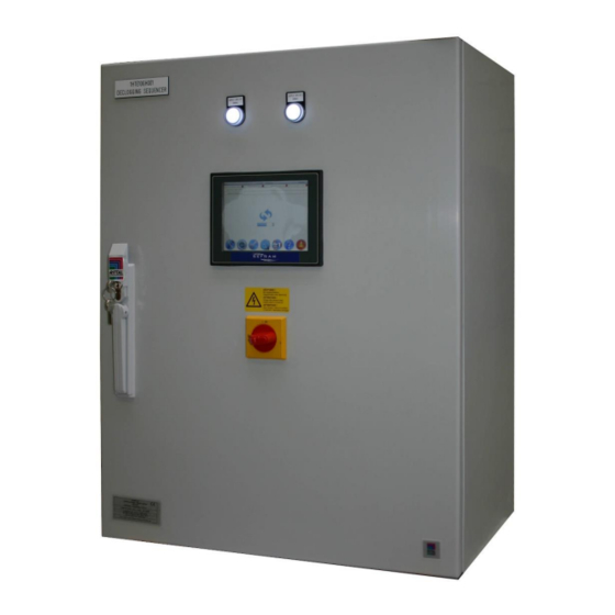
- Page 1 SEQUENCER WITH DIFFERENTIAL PRESSURE SWITCH Master cabinet: example of realization PLACE GUTENBERG - 59175 TEMPLEMARS (France) Tel: +33(0)3 20 60 49 49 - Fax: +33(0)3 20 95 59 62 Email: contact@sefram.eu Web: www.sefram.eu Technical notice FI 72.0567.0221E Page 1 / 45...
-
Page 2: Table Of Contents
- FAULT CHECK position) and by controlling the cell and tank isolation. Electrical faults Mini pressure faults For each SFX+V2, an electrical diagram is associated. Refer to it re-inflation tank faults for connections and dimensions. SV non-opening faults Dust emission faults... - Page 3 SEQUENCER WITH DIFFERENTIAL PRESSURE SWITCH Overview: MASTER box/cabinet: - 7 "touch color HMI - digital inputs management - RELAY output management - analog input / output 4 / 20mA - integrated dP pressure switch SLAVE boxes: (up to 32) - Management of up to 18 EV outputs per box - Integrated Air/Compressed pressure switch - Cell / tank isolation management - Cell position control...
-
Page 4: Characteristics
SEQUENCER WITH DIFFERENTIAL PRESSURE SWITCH CHARACTERISTICS: Master box/cabinet : - Supply voltage 230VAC 50/60Hz Other : on request - Consumption According to configuration - General protection By circuit breaker - Characteristics of digital inputs: Voltage: 24VDC supplied by the device Charge current +/- 1mA - Relay contact characteristics: dry contact. -
Page 5: Slaves Boxes
SEQUENCER WITH DIFFERENTIAL PRESSURE SWITCH Slaves boxes : - Supply voltage : Several versions Solenoid valves voltage DC Version supply AC : 100 to 240V 50-60 Hz Version supply DC : 24Vdc Solenoid valves voltage AC 10% 50-60 Hz 115V/230V ... -
Page 6: Central Unit Board
Red LED: representative of exchanges with the slave boxes Note: a kit exists to backup or restore the SFX+V2 settings to or from a disk file. This kit, consisting of a USB cord and PC software, connects to this card. See the associated documentation (FI72.05666) Technical notice FI 72.0567.0221E... -
Page 7: Slave Board
This identifier determines the role of the box in the configuration of the filter (→ see associated electrical diagram of the SFX+V2). To set this number, the card has a rotary switch and microswitches in order to perform the coding: the number is formed by the position of the rotary switch (0 à... -
Page 8: Protections
SEQUENCER WITH DIFFERENTIAL PRESSURE SWITCH There are two leds (yellow and red) on the slave board: If communication on slave bus detected: Yellow led: representative of receptions (RX) Red led: representative of transmissions (TX) If no communication detected on slave bus: Yellow led: off Red led: flashes regularly Note: possibility of having a local user interface: contact us. - Page 9 SEQUENCER WITH DIFFERENTIAL PRESSURE SWITCH Table 2 : Voltage solenoid valves DC 100 – 240VAC Supply voltage 24VDC Solenoids valves voltage 24VDC 24VDC General protection Self-protected power supply F2.5A against overcurrents SV protection F1.6A F1.6A In the 24V DC power supply version only, the general protection fuse is accessible after removing the front panel of the box.
-
Page 10: User Interface
SEQUENCER WITH DIFFERENTIAL PRESSURE SWITCH USER INTERFACE : General : Name of the page Current date and time Current security level The possible actions by the HMI are associated with the security level in which the system is See page Security for more information : link to CYCLE page : link to previous page : link to next page... -
Page 11: Cycle
SEQUENCER WITH DIFFERENTIAL PRESSURE SWITCH Cycle : 1. Visual on the run orders present / operation in progress Information transmitted by the DCS via a COM or by manual override via the HMI These operating orders come from the COM DCS according to the MODBUS exchange table specific to the configuration : inactive GREEN... -
Page 12: About
SEQUENCER WITH DIFFERENTIAL PRESSURE SWITCH 11. Link to the pages of Historical : faults and events 12. Link to the page Security 13. Link to the page HMI parameters 14. Link to the page Langue 15. Link to the page A propos de 16. -
Page 13: Security
Confirm with the ENT key 5. Export / Save the parameters set into memory by pressing the icon Used to make a backup of the SFX+V2 parameters in a reserved memory on the central unit card. Access in manufacturer level. -
Page 14: Hmi
SEQUENCER WITH DIFFERENTIAL PRESSURE SWITCH HMI : Access to the HMI settings is made by pressing the icon 1. Access to the date and time setting by pressing the icon 2. Access to the recalibration of the HMI touch screen by pressing the icon •... -
Page 15: Languages
SEQUENCER WITH DIFFERENTIAL PRESSURE SWITCH 3. Access to the HMI brightness adjustment by pressing the icon 4. Safe removal of the USB key by pressing the icon Languages : Access to the language setting is made by pressing the icon 3 languages are available: Serbian, English and French Press the icon representing the desired language Technical notice... -
Page 16: Parameters
SEQUENCER WITH DIFFERENTIAL PRESSURE SWITCH Parameters : Access to the various sequencer parameters is made by pressing the icon The parameters are classified according to their function: • Filter configuration Display of the number of cells, tanks, number of solenoid valves, etc. which compose the filter Designation of the declogging cells, tanks and solenoid valves •... -
Page 17: Sequencer / Filter Configuration
When the SFX+V2 loses the run orders, the cleaning cycle has 2 stop modes: • Stop "on cycle": the SFX+V2 stops the declogging cycle as soon as the run order is lost. The cycle will resume where it was stopped when the run order is present again. - Page 18 SEQUENCER WITH DIFFERENTIAL PRESSURE SWITCH Sequencer / filter configuration (2/4) : From this page, it is possible to name each of the tanks constituting the filter. These names then appear in the CYCLE page, page where it is possible to view the progress of the declogging cycle.
- Page 19 SEQUENCER WITH DIFFERENTIAL PRESSURE SWITCH Sequencer / filter configuration (3/4) : From this page, it is possible to name each of the cell constituting the filter. These names then appear in the CYCLE page, page where it is possible to view the progress of the declogging cycle.
- Page 20 SEQUENCER WITH DIFFERENTIAL PRESSURE SWITCH Sequencer / filter configuration (4/4) : From this page, it is possible to name the solenoid valves constituting the filter. For this part, it is considered that the name of a solenoid valve consists of: •...
- Page 21 SEQUENCER WITH DIFFERENTIAL PRESSURE SWITCH Operations to do: • Click in zone "1" the cell whose solenoid valves you wish to name • Display of the selected cell in zone "2" • Click in zone 3 so that the alphanumeric keypad appears •...
-
Page 22: Online Shooting Sequence
SEQUENCER WITH DIFFERENTIAL PRESSURE SWITCH Online shooting sequence: This page allows you to configure, at manufacturer level, the declogging order for an ONLINE declogging cycle. In an declogging process, it may be advantageous to declog the same “ramp” several times in the same cycle. By adjusting the number of ONLINE steps, it will be possible in the same cycle to assign one or more solenoid valves to different pulse sequence numbers. - Page 23 SEQUENCER WITH DIFFERENTIAL PRESSURE SWITCH 3. Number of the selected step Possibility to select the step number either by selecting the step in table "7" or by button "10" "Go to Shooting n °" 4. Number of the cell and the solenoid valve of the cell stored, associated with the number of the selected step 5.
-
Page 24: Operating Time
SEQUENCER WITH DIFFERENTIAL PRESSURE SWITCH Operating time : Settings accessible in maintenance level 1. T1: Pulse time on an declogging solenoid valve. Adjustable from 30 to 2550 ms. Note: setting rounded to within 10ms. Or, depending on configuration, setting from 3 to 255 1 / 100th of a second 2. - Page 25 If the SFX+V2 is equipped with the dust emission check option: outside the declogging cycle, the "dust emission" input is monitored. If a fault is indicated by the sensor for at least a period of T19, then the SFX+V2 displays a general dust emission fault (see fault check → dust emission fault).
-
Page 26: Counters
SEQUENCER WITH DIFFERENTIAL PRESSURE SWITCH Counters : The SFX+V2 manages different counters for the operator and the manufacturer: • Number of declogging cycles done • Number of declogging pulses done Possibility of initializing the counters associated with the operator in Maintenance level. -
Page 27: Dust Emission
DIFFERENTIAL PRESSURE SWITCH Dust emission : This page is only accessible if the dust emission check option has been integrated into the SFX+V2 during the study. 1. Allows to activate or deactivate the dust emission check option integrated in the SFX+V2 Access at Manufacturer level 2. -
Page 28: Compressed Air
SEQUENCER WITH DIFFERENTIAL PRESSURE SWITCH Compressed Air : 1. The tank mini pressure threshold is used to monitor the pressure in the tanks apart from declogging. This threshold is used to create the mini pressure faults. (see fault check → mini pressure faults). Threshold adjustable from 0 to 6 bars. -
Page 29: Customer Communication
SEQUENCER WITH DIFFERENTIAL PRESSURE SWITCH Customer communication : This page is used to define the characteristics of the MODBUS client communication. Settings accessible in Maintenance or Manufacturer level. 1. Speed setting : 2400, 4800, 9600, 19200, 38400, 57600 or 115200 bauds 2. -
Page 30: Manual Mode
SEQUENCER WITH DIFFERENTIAL PRESSURE SWITCH Manual mode : From this page, it is possible, regardless of the presence of the run order, to force either: • continuous declogging • a certain number of declogging cycles • the activation of a solenoid valve Access at Maintenance or Manufacturer level. -
Page 31: Historical
SEQUENCER WITH DIFFERENTIAL PRESSURE SWITCH Historical : Access to the historical of faults and events is made by pressing the icon The system can record up to 9999 faults and events combined. As soon as it reaches this threshold, it will overwrite the oldest faults and events. 1. -
Page 32: Faults
SEQUENCER WITH DIFFERENTIAL PRESSURE SWITCH Historical faults: 1. Fault number 2. Time and date of appearance of the fault 3. Time and date of disappearance of the fault 4. Designation of the fault 5. Recording of the faults historical and events in .xls format on a USB key by pressing the icon File name: Alarm &... - Page 33 SEQUENCER WITH DIFFERENTIAL PRESSURE SWITCH Reminder: to safely remove the USB key, please click on the icon available in the settings of the HMI page. WARNING: if faults are present, and if there is a power-off of the cabinet, then, when power-on, these faults will reappear in the historical with the date / time of the power-on (not their real date of appearance).
-
Page 34: Events
SEQUENCER WITH DIFFERENTIAL PRESSURE SWITCH Historical events: 1. Event number 2. Time and date of appearance of the event 3. Time and date of disappearance of the event 4. Designation of the event 5. Recording of the faults historical and events in .xls format on a USB key by pressing the icon File name: Alarm &... - Page 35 SEQUENCER WITH DIFFERENTIAL PRESSURE SWITCH Reminder: to safely remove the USB key, please click on the icon available in the settings of the HMI page. WARNING: if events are still active (not disappeared), and if there is a power-off of the cabinet, then, when power-on, these events will reappear in the historical with the date / time of the power-on (not their real date of appearance).
-
Page 36: Current Faults
SEQUENCER WITH DIFFERENTIAL PRESSURE SWITCH Current faults: Access to the current faults page by pressing the icon Reminder: the icon on the CYCLE page only appears if a minimum 1 fault is present 1. Number of present faults 2. Time and date of appearance of present faults 3. -
Page 37: Operation
If a filter is designed to have cells in maintenance, they are not declogged when they are in maintenance. If the compressed air is managed, the SFX+V2 does not declog the solenoid valves associated with a tank with a mini pressure fault or re-inflation faults. -
Page 38: Online
SEQUENCER WITH DIFFERENTIAL PRESSURE SWITCH Online : ONLINE mode is available depending on the configuration. Declogging in ONLINE mode consists of actioning the solenoid valves according to the ONLINE shooting sequence configured (see Parameters → Online shooting sequence). When the run order appears, the cycle begins at step 1 of the ONLINE sequence. When the run order disappears, two cases: - If the choice is "declogging stop: end of cycle": the cycle continues until the last step of the sequence (corresponding to number of steps in the online sequence) -
Page 39: Offline
SEQUENCER WITH DIFFERENTIAL PRESSURE SWITCH Offline : OFFLINE mode is available depending on the configuration. Declogging in OFFLINE mode consists in isolating the cells according to the OFFLINE-CELL declogging sequence, then actioning the solenoid valves of this cell according to the OFFLINE-SV declogging sequence. (see Parameters →... -
Page 40: Fault Check
Also, when reset a mini pressure fault, the SFX+V2 authorizes inflation by acting on the isolation SV, and initializes time T8. The minimum pressure must be reached before the end of time T8 otherwise the fault is generated again, the tank is isolated. -
Page 41: Re-Inflation Tank Faults
The pulse on an declogging SV causes a pressure drop in the tank and initiates a time T9. If, at the end of time T9, the tank is not re-inflated, the SFX+V2 generates a re-inflation fault and isolates the concerned tank. -
Page 42: Dust Emission Faults
Note: The SPX50 sensor has the advantage of being able to quickly detect dust peaks on the one hand and simultaneously monitor the average emission rejection against an alarm threshold on the other hand. These two information are given to the SFX+V2 via a single relay (see instructions associated with the SPX50 dust emission control device). -
Page 43: Link Faults
Cell opening / closing faults : Depending on the configuration, the SFX+V2 can manage the opening or closing faults of the cells of a filter (in the case of OFFLINE operation for example). -
Page 44: Precautions
59175 TEMPLEMARS FRANCE CERTIFICATE : The SFX+V2 device respects the European directives (EMC, LVD), which concerns it. However, it must be used correctly in applications for which it is intended, and should be linked or near CE approved products. Certificate available on request. -
Page 45: General Instructions Of
Personnel working on the devices must be familiar with the of the material in complete safety. safety rules and requirements in force regarding the In the event of a problem, please contact Sefram. components, devices, machines and electrical installations. V. MAINTENANCE Before any intervention on the cabinet, the equipment must be The device does not require any special maintenance.
Need help?
Do you have a question about the SFX+V2 and is the answer not in the manual?
Questions and answers