
Related Manuals for Loop Telecom Loop-IP6702A TDMoEthernet


Summary of Contents for Loop Telecom Loop-IP6702A TDMoEthernet
- Page 1 Loop-IP6702A TDMoEthernet User’s Manual Loop Telecommunication International, Inc. 6F, Number 8, Hsin Ann Rd., Hsinchu Science Park, Hsinchu, 30078 Taiwan Tel: +886-3-5787696 Fax: +886-3-5646272...
- Page 2 © 2019 Loop Telecommunication International, Inc. All rights reserved. Version 5 5th August, 2019...
- Page 3 IP6702A ’ Disclaimers Manufacturer assumes no responsibility for any damage or loss resulting from the use of this manual. Manufacturer assumes no responsibility for any loss or claims by third parties that may arise through the use of this product. III.
- Page 4 IP6702A ’ Bitte führen Sie das Gerät am Ende seinerLewbensdauer den zue Verfügung stehended Rückgabeund Sammelsystemen zu. At the end of the product's useful life, please dispose of it at appropriate collection points provided in your country Une fois le produit en fin devie, veuillez le déposer dans un point de recyclage approprié.
-
Page 5: Table Of Contents
Table of Contents PRODUCT DESCRIPTION ................1 1.1. Description ....................1 1.2. Features ....................1 1.3. Applications..................... 3 1.4. Specifications ..................4 INSTALLATION ....................7 2.1. Site Selection ..................7 2.2. Mechanical Installation ................7 2.3. Assignment Information ................ 11 2.4. - Page 6 5.3.1. Bundle IP Setup ................42 5.3.2. TimeSlot to Bundle Setup .............. 43 5.3.3. Bundle Link Setup ................43 5.4. Firmware Transfer ................. 46 5.4.1. Download Firmware ............... 47 5.4.2. Download Boot Strapper ..............47 5.4.3. Download Configuration ..............48 5.4.4.
- Page 7 5.16.1.12. Port Alarm History ............74 5.16.2. T1 Sun-Menu ................75 5.16.2.1. Port Setup ................75 5.16.2.2. Port Loopback Test ............76 5.16.2.3. Clear Performance Data ............ 77 5.16.2.4. Port Alarm Setup ............... 77 5.16.2.5. Clear Alarm History ............78 5.16.2.6.
- Page 8 List of Figures FIGURE 1-1 IP6702A POINT-TO-POINT APPLICATION .......... 3 FIGURE 1-2 IP6702A FRACTIONAL E1 POINT TO MULTIPOINT APPLICATION ... 3 FIGURE 1-3 IP6702A E1/LAN ETHERNET RADIO APPLICATION ......3 FIGURE 2-1 FRONT PANEL VIEW ................7 FIGURE 2-2 REAR PANEL VIEW (AC POWER) ............8 FIGURE 2-3 REAR PANEL VIEW (DC POWER) ............
- Page 9 List of Tables TABLE 2-1 DB9S CONSOLE PORT PIN ASSIGNMENT ......... 11 TABLE 2-2 ALARM RELAY CONNECTOR .............. 11 TABLE 2-3 POWER CONNECTOR ................. 11 TABLE 2-4 RJ45 FOR ETHERNET PORT ............... 11 TABLE 2-5 X.21/DB15 DTE PORT PIN DEFINITION ..........11 TABLE 2-6 RS422 DTE PORT PIN DEFINITION .............
-
Page 10: Product Description
Chapter 1 Product Description IP6702A TDMoEthernet PRODUCT DESCRIPTION 1.1. Description The Loop-IP6702A device allows operators to transport Unframed/Framed 1 E1 (1 Unframed/Framed T1) data stream with timing information over PSN (Packet Switched Network) via Pseudowire Protocol – SAToP or CESoPSN . Another IP6702A converts the received packet stream back to original E1 or T1 data stream with original timing information. - Page 11 Chapter 1 Product Description IP6702A TDMoEthernet • Maximum 16 Pseudowires • PDV Compensation Depth: up to 256 ms • Jitter Buffer Size: up to 256 frames Pseudowire Diagnostic Function • Built-in BERT for E1/T1 to Line or WAN direction • IP –...
-
Page 12: Applications
Chapter 1 Product Description IP6702A TDMoEthernet 1.3. Applications IP6702A IP6702A E1/T1 E1/T1 Network 10/100 BaseT or 100 FX 10/100 BaseT 10/100 BaseT Management Figure 1-1 IP6702A Point-to-Point Application Fractional E1 Point to Multipoint Application IP6702A FE1/T1 IP6702A 64K, Pseudowire #1 FE1/T1 IP Network RS422... -
Page 13: Specifications
Chapter 1 Product Description IP6702A TDMoEthernet 1.4. Specifications Specifications SFP Optical Module Please refer to SFP optical module brochure for detail. Ethernet Optical Interface Number of Ports: Optical port Optical Port Speed : 100 BaseFX (802.3u) Connector: Ethernet Electrical Interface Number of Ports: Speed: 10/100 BaseT (802.3i, 802.3u) - Page 14 Chapter 1 Product Description IP6702A TDMoEthernet Alarm Reports (E1/T1) Alarm History: Date & time, alarm type(i.e. clock loss, LOS, BPV, ES) Alarm Queue: Contains up to 4000 alarm records of latest alarm types, alarm severity, date and time. Diagnostics Test (E1/T1) Loopback: Line loopback and Local loopback Power...
- Page 15 Chapter 1 Product Description IP6702A TDMoEthernet Loop Telecommunication International, Inc.
-
Page 16: Installation
Chapter 2 Installation IP6702A TDMoEthernet INSTALLATION 2.1. Site Selection The following list indicates a site selection guideline. Users need to follow this guideline to select a proper installation site. Location of the Loop-IP6702A unit should be part of the central office equipment layout design. Considerations should be given to entrance cable routing. -
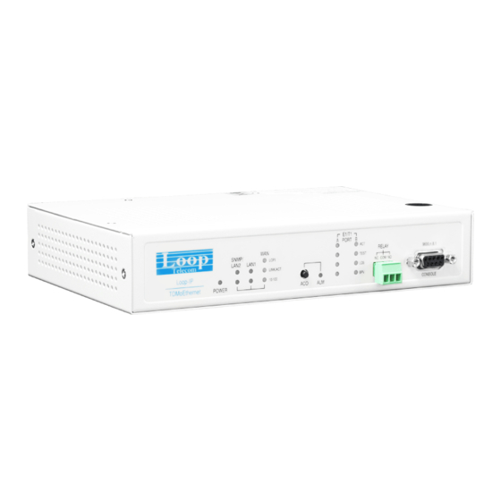
Page 17: Figure 2-2 Rear Panel View (Ac Power)
Chapter 2 Installation IP6702A TDMoEthernet Figure 2-2 Rear Panel View (AC Power) Figure 2-3 Rear Panel View (DC Power) Figure 2-4 Rear Panel View (AoD Power) Chassis Grounding The chassis is grounded when rack mounted. However, for stand alone units or extra grounding protection for rack mounted units, a dedicated chassis ground screw and lock washer is provided. -
Page 18: Figure 2-5 Chassis Grounding
Chapter 2 Installation IP6702A TDMoEthernet Figure 2-5 Chassis Grounding Console port can be connected via RS422 interface to a configuration device a VT100 terminal or equivalent. Pin definition and pin connection of the console port are listed in the following table. J21 J22 J23 J27 Main Board E 1 , RJ ( 120 ohm ) -
Page 19: Figure 2-7 Main Board Jumper Setting Of Line - E1, Bnc (75 Ohm)
Chapter 2 Installation IP6702A TDMoEthernet J21 J22 J23 J27 Main Board E 1 , BNC ( 75 ohm ) Figure 2-7 Main Board Jumper Setting of Line - E1, BNC (75 ohm) Com port J21 J22 J23 J27 Main Board Figure 2-8 Main Board Jumper Setting of Line - T1 Loop Telecommunication International, Inc. -
Page 20: Assignment Information
Chapter 2 Installation IP6702A TDMoEthernet 2.3. Assignment Information Table 2-1 DB9S Console Port Pin Assignment Pin Number Signal Description Data Carrier Detect To DTE Receive Data To DTE Transmit Data From DTE Unassigned Signal Ground Data Set Ready To DTE Unassigned Clear to send To DTE... -
Page 21: Table 2-6 Rs422 Dte Port Pin Definition
Chapter 2 Installation IP6702A TDMoEthernet Signal Timing External Clock Signal Ground Transmit Data Return Control Return Receive Data Return Indication Return Signal Timing Return External Clock Return Unassigned Table 2-6 RS422 DTE Port Pin Definition Pin Number Signal Source Cable Shield Transmit Data Receive Data Request To Send... -
Page 22: Default Setting
Chapter 2 Installation IP6702A TDMoEthernet 2.4. Default Setting Table 2-7 Default Software Configuration Configuration Option Default Frame ON, OFF,CAS,CRC, CAS+CRC Code HDB3, AMI HDB3 INTF 120 OHM, 75OHM 120 OHM E1 Line ON, OFF ON, OFF IDLE CODE 00-FF BUSY,IDLE BUSY Frame D4, None, ESF, ESF &... -
Page 23: Operation
Chapter 3 Operation IP6702A TDMoEthernet OPERATION 3.1. Power On Turn power on by attaching power cable at the rear of the unit. Return to Default Setting. The unit is shipped with factory default setting. 3.2. Self Test If password is enabled, users must enter the password when logging in to gain the privilege to change system configurations on the terminal. -
Page 24: System Configuration
Chapter 3 Operation IP6702A TDMoEthernet 3.5. System Configuration 3.5.1. Console Port The console port allows the user either to use a local VT-100 terminal or use a remote VT-100 terminal via modem for system configuration, diagnostics, polling status reports, etc. The console port Baud rate, data bit length, stop bit length, and parity bit length are defaulted, as shown below. -
Page 25: Report
Chapter 3 Operation IP6702A TDMoEthernet 3.7. Report For E1/T1 line receiver, Loop-IP6702A has two sets of performance registers. These are line and user,. The line performance register tracks the E1/T1 line receiver performance status. The user performance register tracks the E1/T1 line receiver as well, but user may clear at any time. Each performance parameter has ninety six sets of registers to record 24 hours history in 15 minute intervals. -
Page 26: Table 3-6 Led Indication For Main Unit (Rear Panel)
Chapter 3 Operation IP6702A TDMoEthernet Detected any E1/T1 or WAN/LAN or DTE port alarms Link Down LINK/ Link Up Green ETH1 A valid network connection on the Ethernet port. Green 100Mbps Link Down Link Up Green LINK/ A valid network connection on the Ethernet port. ETH2-ET Flashing Active. -
Page 27: Management Port (Ethernet Port)
Chapter 3 Operation IP6702A TDMoEthernet Link Up Green A valid network connection on the RJ-45 ETH port. Flashing Active. Data is being transmitted or received through the RJ-45 ETH port. Green 10Mbps(only for electrical Ethernet) 10/100 Green 100Mbps 3.9. Management Port (Ethernet Port) As two IP6702A are connected: one is set as local unit and the other is set as remote unit. -
Page 28: Maintenance
Chapter 4 Maintenance IP6702A TDMoEthern MAINTENANCE 4.1. Self Test When the Loop-IP6702A is powered up, a complete self-test routine is run to check all I/O ports, read/write memory, and data paths to validate system integrity. During system self test, "TESTING" message and testing code are shown on the VT100 terminal screen. -
Page 29: Figure 4-2 Dte Loopback Block Diagram
Chapter 4 Maintenance IP6702A TDMoEthern Line Ethernet Line Loopback Loopback to Ethernet Figure 4-2 DTE Loopback Block Diagram Loop Telecommunication International, Inc. -
Page 30: Terminal Operation
Chapter 5 Terminal Operation IP6702A TDMoEthernet TERMINAL OPERATION The Loop-IP6702A provides comprehensive report and configuration capability through the console port. By using single-character commands and arrow keys, the Loop-IP6702A can be configured and monitored through the use of a VT-100 terminal. The single-character commands are not case sensitive, except for when using a password. -
Page 31: Figure 5-2 Vt-100 Setup Menu Overview
Chapter 5 Terminal Operation IP6702A TDMoEthernet A -> SNMP System Setup A -> Config Setup B -> V1: Trap Setup B -> SNMP Setup C-> V3: User-Based Security Model Setup S -> System Setup C -> Switch Setup D -> V3: View-Based Access Control Model D ->... -
Page 32: Figure 5-3 Vt-100 Display Menu Overview
Chapter 5 Terminal Operation IP6702A TDMoEthernet A -> Config Display A -> RSTP Display B -> SNMP Display B-> Vlan Display C -> System Display C -> System Info Display C-> Port Speed Display D -> Switch Display D-> Port Statistics E ->... -
Page 33: Figure 5-4 Vt-100 E1/T1 Menu Tree
Chapter 5 Terminal Operation IP6702A TDMoEthernet [DISPLAY] 1-> Port 1-Hour Perf . Report 2-> Port 24-Hour Perf . Report A->Port Line Availability C->Port Configuration I -> Port Status H->Port Alarm History VT100 [E1/T1] [SETUP] S-> Port Seyup L-> Port Loopback Test K->Claer Performance Data M->Port Alarm Setup X->Clear Alarm History... -
Page 34: Log On
Chapter 5 Terminal Operation IP6702A TDMoEthernet 5.1. Log on Follow the procedures below to log on: When the Loop-IP6702A is powered on, the main menu will appear as shown below: I P6 70 2 A == = Main Me nu === 1 2: 05 :1 4 01/1 8/ 201 6 S er ia l N u mb e r D ev ic e Nam e : IP 67 02 A (OCX O) -
Page 35: System Setup
Chapter 5 Terminal Operation IP6702A TDMoEthernet I P6 70 2 A E 1 == = Main Me nu = == 12:06: 00 01/1 8/ 2016 S er ia l N u mb e r : 5 06 D ev ic e Nam e : IP 67 02 A (TCX O) H ar dw a re Ve r si o n : V er.B FP G A: 3 (1 2) S tart Tim e : 12 :0 0: 20 01/ 18 /2 016... -
Page 36: Config Setup
Chapter 5 Terminal Operation IP6702A TDMoEthernet E - > S t atic R oute S et up < < Pr e ss ES C k e y t o ret u rn to Ma in Me nu or enter a com ma nd > > 5.2.1. -
Page 37: Snmp Setup
Chapter 5 Terminal Operation IP6702A TDMoEthernet 5.2.2. SNMP Setup The full menu path for SNMP Setup is as follows: O > Logon S > System Setup B > SNMP Setup The screen of SNMP Setup will show as below. I P6 70 2 A T 1 == = SNMP Se tu p === 1 2: 24 :3 7 01/1 8/ 201 6 A - >... -
Page 38: V1: Trap Setup
Chapter 5 Terminal Operation IP6702A TDMoEthernet < < Pr e ss ES C k e y t o ret u rn to pr eviou s menu or s av e th e se tu p>> Table 5-2 SNMP SystemSetup Field Setting Options Default Setting SNMP Model... -
Page 39: V3: View-Based Access Control Model Setup 1
Chapter 5 Terminal Operation IP6702A TDMoEthernet B oo ts T ot al Us e r: 2 [ Us er 01 ] E ng in e I D : 00 0 0 263F 0 00 0 00 5 0C 60FA8 B9 U se r N am e : lo o p md5 A u t h P ro toc o l: M D5... -
Page 40: V3: Target & Notify Setup
Chapter 5 Terminal Operation IP6702A TDMoEthernet I P6 70 2 A T 1 = == SN MP Setu p (V ACM) == = 1 2: 32 :1 5 01/1 8/ 201 6 [ Ac ce s s] 1/ 1 G ro up Na m e : i niti a l S ec ur i ty Mo d el : V 3(US M ) -
Page 41: Rstp Setup
Chapter 5 Terminal Operation IP6702A TDMoEthernet I P6 70 2 A = == Switch S et up == = 1 2: 16 :0 1 01/1 8/ 201 6 A - > R S TP Set up B - > V l an Se t u p C - >... -
Page 42: Table 5-4 Rstp Setup
Chapter 5 Terminal Operation IP6702A TDMoEthernet < < Pr e ss ES C k e y t o ret u rn to pr eviou s menu o r save t he s etup >> The RSTP Enabled screen: I P 6 702 A == = RSTP S et up == = 12 :2 6: 42 01/ 18 /20 16 A RR OW KE Y S: CU R S OR MOVE , T A B: RO LL OP TI ONS... -
Page 43: Vlan Setup
Chapter 5 Terminal Operation IP6702A TDMoEthernet E T H2 F w d 0 __ _ _ 0 00 sh ar ed E T H3 Di s 0 00 0 0 0 00 sh ar ed E T H4 Di s 0 00 0 0 0 00 sh ar ed... -
Page 44: Vlan Configuration Setup
Chapter 5 Terminal Operation IP6702A TDMoEthernet I P 6 702 A == = VLAN S et up == = 12 :3 7: 53 01/ 18 /20 16 A - > V L AN Co nf igur atio n Setu p B - >... -
Page 45: Vlan Port Setup
Chapter 5 Terminal Operation IP6702A TDMoEthernet < < Pr e ss ES C k e y t o ret u rn to pr eviou s menu or s av e th e se tu p>> Table 5-8 VLAN Configuration Setup Field Setting Options Default Setting... -
Page 46: Port Speed Setup
Chapter 5 Terminal Operation IP6702A TDMoEthernet 8 02 .1 Q : Di s ab l e [ In tf ] [ PV I D] E T H1 : 00 0 1 E T H2 : 00 0 1 E T H3 : 00 0 1 E T H4 : 00 0 1... -
Page 47: Password Setup
Chapter 5 Terminal Operation IP6702A TDMoEthernet < < Pr e ss ES C k e y t o re t u rn to mai n menu or sa ve set up >> Table 5-10 Port Speed Setup Field Setting Options Default Setting Physical... -
Page 48: Table 5-12 Static Route Setup
Chapter 5 Terminal Operation IP6702A TDMoEthernet I P 6 702 A == = S t atic Route S et up = == 1 2:49 :35 01/ 18 /201 6 A RR OW KE Y S: CU R S OR MOVE , P l ea s e Input : nnn. nnn.n nn .nnn , BA CK SPAC E to edi t N et_ De s ti n at i on Net m a sk Gat ew ay _A dd ress... -
Page 49: Ssh Setup
Chapter 5 Terminal Operation IP6702A TDMoEthernet PC (Remote) Gateway IP6702A(Local) IP: 10.1.1.1 11.1.254.254 Gateway: 10.1.254.254 Internet Figure 5-6 Static Route Setup 5.2.6. SSH Setup The full menu path for SSH Setup is as follows: O > Logon S > System Setup F >... -
Page 50: Radius Setup
Chapter 5 Terminal Operation IP6702A TDMoEthernet Field Setting Options Default Setting SSH Server ON, OFF 5.2.7. RADIUS Setup The full menu path for RADIUS Setup is as follows: O > Logon S > System Setup G > RADIUS Setup I P 6 70 2 A T 1 === RADIUS setu p == = 1 6: 29 :1 1 0 1/ 18/2 01 6 A RR OW KE Y S: CU R S OR MOVE , T A B: RO LL OP TI ONS... -
Page 51: Bundle Ip Setup
Chapter 5 Terminal Operation IP6702A TDMoEthernet < < Pr e ss ES C k e y t o ret u rn to Ma in Me nu or enter a com ma nd > > 5.3.1. Bundle IP Setup The full menu path for Bundle IP Setup is as follows: O >... -
Page 52: Timeslot To Bundle Setup
Chapter 5 Terminal Operation IP6702A TDMoEthernet 5.3.2. TimeSlot to Bundle Setup The full menu path for TimeSlot to Bundle Setup is as follows: O > Logon T > Bundle Setup B> TimeSlot to Bundle Setup The screen of TimeSlot to Bundle Setup will show as below. I P6 70 2 A T 1 = == Ti m eS lot t o Bund le Se tu p == = 1 2:07 :5 6 01/1 8/ 201 6... -
Page 53: Table 5-15 Bundle Link Setup
Chapter 5 Terminal Operation IP6702A TDMoEthernet P 6 7 02 == = B und le Li nk Setu p 12 :5 7:1 0 01 /1 8/20 16 A RR OW KE Y S: CU R S OR MOVE , T A B: RO LL OP TI ONS P or t : A B un d le ID : 0 S TA TUS... -
Page 54: Figure 5-7 Stratum Setting
Chapter 5 Terminal Operation IP6702A TDMoEthernet Number of frame 8 ~ 1500 0016 (See Note1) Jitter Tol 1 ~ 256 Jitter Buf 1 ~ 256 VLAN OFF, 1-VLAN, 2-VLAN When format is SAToP Number of frame 8 ~ 1500 0016 Jitter Tol 1 ~ 256 Jitter Buf... -
Page 55: Firmware Transfer
Chapter 5 Terminal Operation IP6702A TDMoEthernet buffer size This area is empty and can be used to store incoming bursts delay This area is full and there is still data to send on the line if incoming data is missing due to network delays. -
Page 56: Download Firmware
Chapter 5 Terminal Operation IP6702A TDMoEthernet I P 6 702 A = = = F irmware Tran sfer == 13 :00: 39 01 /18/20 16 A - > D ow n loa d Firmware B - > D ow n loa d Boot Strap pe r C - >... -
Page 57: Download Configuration
Chapter 5 Terminal Operation IP6702A TDMoEthernet The screen of Download Boot Strapper will show as below. Enter the TFTP server IP and the firmware file name you would like to download. I P6 70 2 A = = = D ow nload B ootu p Cod e === 1 2:32 :2 3 01/1 8/ 201 6 A RR OW KE Y S: CU R S OR MOVE , P l ea s e Input : nnn. -
Page 58: Upload Configuration
Chapter 5 Terminal Operation IP6702A TDMoEthernet 5.4.4. Upload Configuration The full menu path for Upload Configuration is as follows: O > Logon W> Firmware Transfer D> Upload Configuration The screen of Upload Configuration will show as below. Enter the TFTP Server IP and the Config file name to upload configuration. I P 6 702 A = == U pload C on figu ra ti on == = 1 3:07 :20 0 1/18/20 16... -
Page 59: Clock Source Setup
Chapter 5 Terminal Operation IP6702A TDMoEthernet Table 5-16 Boot Bank Change Field Setting Options Default Setting Next Boot Bank 1, 2 5.5. Clock Source Setup The full menu path for Clock Source Setup is as follows: O > Logon K > Clock Source Setup Input the port number (A~B): A The screen of Clock Source Setup will show as below. -
Page 60: System Alarm Setup
Chapter 5 Terminal Operation IP6702A TDMoEthernet 5.6. System Alarm Setup The full menu path for Syatem Alarm Setup is as follows: O > Logon M> System Alarm Setup The screen of System Alarm Setup will show as below. I P 6 702 A == = S y stem A la rm Se tu p === 13:1 0: 53 01 /1 8/20 16 A RR OW KE Y S: CUR S OR MOV E , TA B: RO L L OPTIO NS... -
Page 61: Als/Apsd Setup
Chapter 5 Terminal Operation IP6702A TDMoEthernet I P 6 702 A == = SNTP S etup = == 13 :11: 24 01 /1 8/20 16 A RR OW KE Y S: CU R S OR MOVE , T A B: RO LL OP TI ONS S NT P O N/ O FF : O F F S NT P s er v er 1 : 000 .00 0 . -
Page 62: Store/Retrieve Configuration
Chapter 5 Terminal Operation IP6702A TDMoEthernet ALS enable pulse repetition time for automatic 60 ~ 300 restart(sec) 5.9. Store/Retrieve Configuration The full menu path for Store/Retrieve Configuration is as follows: O > Logon V > Store/Retrieve Configuration The screen of Store/Retrieve Configuration will show as below. I P 6 702 A = ==S t or e /R e trieve Conf ig ur ation== = 1 3:14 :4 3 01/ 18 /201 6... -
Page 63: Config Display
Chapter 5 Terminal Operation IP6702A TDMoEthernet 5.10.1. Config Display The full menu path for Config Display is as follows: O > Logon C > System Display A > Config Display The screen of Config Display will show as below. I P6 70 2 A = = = Config Disp lay = == 1 2: 38 :3 4 01/1 8/2 01 6 I P Ad d r. -
Page 64: System Info Display
Chapter 5 Terminal Operation IP6702A TDMoEthernet 5.10.3. System Info Display The full menu path for System Info Display is as follows: O > Logon C > System Display C > System Info Display The screen of System Info Display will show as below. I P6 70 2 A = = = S ys tem Inf o Di splay = == 1 2:39 :0 9 01/1 8/ 201 6... -
Page 65: Rstp Display
Chapter 5 Terminal Operation IP6702A TDMoEthernet 5.10.4.1. RSTP Display The full menu path for RSTP Display is as follows: O > Logon C > System Display D > Switch Display A > RSTP Display The screen of RSTP Display will show as below. I P 6 702 A == = Rstp D ispl ay == = 1 2:02 :2 0 0 1/18 /2 016... -
Page 66: Vlan Configuration
Chapter 5 Terminal Operation IP6702A TDMoEthernet 5.10.4.2.1. VLAN Configuration The full menu path for VLAN Configuration is as follows: O > Logon C > System Display D > Switch Display C > VLAN Display A > VLAN Configuration The screen of VLAN Configuration will show as below. I P 6 702 A = == V LA N Config ur a tion Disp la y=== 13 :16: 29 01 /1 8/20 16... -
Page 67: Port Speed Display
Chapter 5 Terminal Operation IP6702A TDMoEthernet 5.10.4.3. Port Speed Display The full menu path for Port Speed Display is as follows: O > Logon C > System Display D > Switch Display C > Port Speed Display The screen of Port Speed Display will show as below. I P6 70 2 A = == Po rt Spee d Di splay = == 1 2:41 :5 1 01/18/2 01 6... -
Page 68: Mac Table Display
Chapter 5 Terminal Operation IP6702A TDMoEthernet 5.10.4.5. MAC Table Display The full menu path for MAC Table Display is as follows: O > Logon C > System Display D > Switch Display E > MAC Table Display The screen of MAC Table Display will show as below. I P6 70 2 A = == MA C Table Dis play == = 1 2: 43 :2 2 01/1 8/ 201 6... -
Page 69: Bundle Display
Chapter 5 Terminal Operation IP6702A TDMoEthernet 5.11. Bundle Display The full menu path for Bundle Display is as follows: O > Logon J > Bundle Display The screen of Bundle Display will show as below. I P 6 702 A = == Bundle Di sp lay == = 13: 46:0 0 0 1/ 18/2 016 A - >... -
Page 70: Ds0 Tslot To Bundle Display
Chapter 5 Terminal Operation IP6702A TDMoEthernet 5.11.2. DS0 TSlot to Bundle Display The full menu path for DS0 TSlot to Bundle Display is as follows: O > Logon J > Bundle Display B > DS0 TSlot to Bundle Display The screen of DS0 TSlot to Bundle Display will show as below. I P6 70 2 A == = DS0 TS l ot to Bund le Di sp lay = == 1 2: 44:4 0 0 1/ 18/2 01 6... -
Page 71: Bundle Summary
Chapter 5 Terminal Operation IP6702A TDMoEthernet 5.11.4. Bundle Summary The full menu path for Bundle Summary is as follows: O > Logon J > Bundle Display D> Bundle Summary The screen of Bundle Summary will show as below. I P 6 702 A = == Bundle Su mm ary == = 13: 47:5 9 0 1/ 18/2 016 P o BI D U D P... -
Page 72: Clock Source Display
Chapter 5 Terminal Operation IP6702A TDMoEthernet < < SP A CE ba r t o re f resh or ES C k ey re tu rn t o mai n menu > > Link : up means it have receiving remote UDP traffic ; down means it do not have NOTES: 1. -
Page 73: Alarm Queue Summary
Chapter 5 Terminal Operation IP6702A TDMoEthernet I P 6 702 A = == Cl o ck So ur ce Di splay = == 1 3:49:4 6 0 1/18 /2 016 M as te r _C l k S ou r c e : IN T E RN A L S ec on d _C l k S ou r c e : IN T E RN A L C ur re n t C lo c k : MA S TER _ CL K... -
Page 74: Currently-Active Alarm Summary
Chapter 5 Terminal Operation IP6702A TDMoEthernet 5.14. Currently-Active Alarm Summary The full menu path for Currently-Active Alarm Summary is as follows: O > Logon R > Currently-Active Alarm Summary The screen of Currently-Active Alarm Summary will show as below. I P 6 702 A = == C urr e nt Acti ve Ala rm Sum mar y = == 14: 05:5 7 01 /18/ 20 16 <... -
Page 75: E1/T1 Sub-Menu
Chapter 5 Terminal Operation IP6702A TDMoEthernet 5.16. E1/T1 Sub-Menu 5.16.1. E1 Sun-Menu Press P to choose a port. Use the tab key to select. Press enter to apply. Now the system should be switched to the card type and the port you want. This information is indicated on the upper left corner of the screen. -
Page 76: Port Loopback Test
Chapter 5 Terminal Operation IP6702A TDMoEthernet Table 5-21 Port Setup Field Setting Options Default Setting CODE HDB3, AMI HDB3 INTF 75 OHM, 120OHM 120 OHM ON, OFF ON, OFF IDLE CODE 0 ~ 9, A ~ F BUSY, IDLE BUSY Table 5-22 Defining Parameters in Port Setup Parameters Definition... -
Page 77: Clear Performance Data
Chapter 5 Terminal Operation IP6702A TDMoEthernet 5.16.1.3. Clear Performance Data The full menu path for Clear Performance Data Test is as follows: O > Logon P > Choose a Port K > Clear Performance Data The screen of Clear Performance Data will show as below. E 1 Por t A = == E1/ T1 Port == = 1 4: 19:41 0 1/18 /2 016... -
Page 78: Clear Alarm History
Chapter 5 Terminal Operation IP6702A TDMoEthernet Table 5-23 Port Setup Field THRESHOLD ALARM Setting Options Default Setting Options Default DISABLE DISABLE DISABLE MAJOR,CRITICAL, DISABLE MINOR,INFO,DISABLE 10E-5 ~ 10E-9 10E-5 DISABLE 001 ~ 900 DISABLE 001 ~ 900 DISABLE 001 ~ 900 DISABLE 5.16.1.5. -
Page 79: Port 1-Hour Perf. Report
Chapter 5 Terminal Operation IP6702A TDMoEthernet T i me Sl ots M ap : F TT TT T TT T TT TT T TT TTT TT T TT TT TT TTT T En a bl e : D IS ABL E T e st Pa tte r n : 2 ^ 15 - 1 <... - Page 80 Chapter 5 Terminal Operation IP6702A TDMoEthernet E 1 Por t A = = = P o rt 1 -Hour Per f. R eport === 14:5 1:30 01/ 18/2016 > > Se l ec t R e gi s t er Typ e ? * US E R LINE Use TAB key to select register type, USER or LINE.
-
Page 81: Port 24-Hour Perf. Report
Chapter 5 Terminal Operation IP6702A TDMoEthernet LINE E 1 Por t A = = = P o rt 1 -Hour Per f. Re port == = 12:0 8:46 01 /1 8/ 2016 L I N E - - Val id Se c on d s i n Cu rr en t 1 5 -Mi n In te rval : 46 9 seco nd s (ES) ( UA S) (BES ) -
Page 82: Port Line Availability
Chapter 5 Terminal Operation IP6702A TDMoEthernet E 1 Por t A = = = Po rt 2 4- Hour Pe rf . Repor t === 12:0 9: 11 01/1 8/20 16 U SE R E S - - Va l id Sec on d s i n Cur r en t 1 5 -Mi n In te rval : 49 3 seco nd s - - Va l id 15 - Mi n In t erv a l s i n C ur r ent 24 - Hou r In terv al : 0 (ES) ( UA S) -
Page 83: Port Status
Chapter 5 Terminal Operation IP6702A TDMoEthernet E 1 P or t A = = Po rt Con fi gurati on = = 1 5: 03:56 0 1/18 /2 01 6 F RA M E = O N C OD E = H DB 3 I NT F = 1 20 O H M... -
Page 84: T1 Sun-Menu
Chapter 5 Terminal Operation IP6702A TDMoEthernet E 1 P o rt A = == Po r t Ala rm Hi st or y === 1 5:08 :1 8 0 1/18 /2 016 L O C AL [ AL AR M -T Y PE ] [T H R ESH OL D] [ CU R R - STAT E] [COU NT ]... -
Page 85: Port Loopback Test
Chapter 5 Terminal Operation IP6702A TDMoEthernet T 1 P or t A = = = Port Set up = == 12: 52 :5 5 0 1/ 18/2 01 6 A RR OW KE Y S: CU R S OR MOVE , T A B: RO LL OP TI ONS F RA M E = D 4 C OD E... -
Page 86: Clear Performance Data
Chapter 5 Terminal Operation IP6702A TDMoEthernet L > Port Loopback Test The screen of Port Loopback Test will show as below. Use arrow keys to move the cursor and enter key to start the loopback. T 1 Po rt A = = = Po r t Lo op ba ck Te st == = 14 :1 8:57 01 /18 /2 016 A RR OW KE Y S : C U R SO R MOV E , EN T ER KEY : ITEM SELE CT... -
Page 87: Clear Alarm History
Chapter 5 Terminal Operation IP6702A TDMoEthernet The screen of Port Alarm Setup will show as below. T 1 P o rt A = == P o rt Al arm S et up === 1 2:02 :43 0 1/18/20 16 A RR OW KE Y S: CU R S OR MOVE , T A B: RO LL OP TI ONS [ TY PE ] [ T HR E SH O L D] [ A LA R M] Y EL... -
Page 88: Bert Test
Chapter 5 Terminal Operation IP6702A TDMoEthernet T 1 Por t A = == E1/ T1 Port == = 1 4: 34:44 0 1/18 /2 016 [ DI SP L AY ] [ SE TU P] 1 - > P or t 1 - Ho u r P e rf. R ep o rt S - >... -
Page 89: Port 1-Hour Perf. Report
Chapter 5 Terminal Operation IP6702A TDMoEthernet T 1 Po r t A == = Bert te st = == 1 3: 01 :5 4 0 1/ 18 / 20 1 6 A RR OW KE Y S: CU R S OR MOVE , T A B: RO LL OP TI ONS Ty pe : S EL ECT Dir ec t... -
Page 90: Port 24-Hour Perf. Report
Chapter 5 Terminal Operation IP6702A TDMoEthernet T 1 Po r t A = == P o rt 1 -Hour Per f. Re port == = 13:0 4:35 01 /1 8/ 2016 U S E R - - Va l id Sec on d s i n Cur r en t 1 5 -Mi n In te rval : 27 5 seco nd s (ES) ( UA S) (BES ) -
Page 91: Port Line Availability
Chapter 5 Terminal Operation IP6702A TDMoEthernet T 1 Po r t A == = P o rt 2 4 - Hour Pe rf . R e por t = == 18:3 2: 16 01/1 8/20 16 > > Se l ec t R e gi s t er Type ? * US E R LINE Use TAB key to select register type and the parameter. -
Page 92: Port Configuration
Chapter 5 Terminal Operation IP6702A TDMoEthernet T 1 P o rt A = == Po rt Line Ava il ab il it y = == 1 3: 05 :50 01 /1 8/2 016 - - Li n e A vai la b i li ty du r in g L a st 24 - Hou r: Va l id Sec on d s : 39 5 0 s eco nds Av a il a ble S e co n ds... -
Page 93: Port Alarm History
Chapter 5 Terminal Operation IP6702A TDMoEthernet T 1 P or t A = = = Port Sta tu s = == 1 3: 06:22 0 1/18/20 16 - - LI N E - - LO S : L O S LO F : L O F RC V A I S : N O... -
Page 94: Port Loopback Setup
Chapter 5 Terminal Operation IP6702A TDMoEthernet P OR T B D T E = == Port Menu === 12 :13:25 01/18/2 01 6 [ DI SP L AY ] [SETUP ] C - > P or t Sy st e m S etup D is p la y L - >... -
Page 95: Port System Setup
Chapter 5 Terminal Operation IP6702A TDMoEthernet P OR T B DT E = == P ort Al ar m Set up == = 1 2: 16:12 0 1/18/20 16 A RR OW KE Y S: CU R S OR MOVE , T A B: RO LL OP TI ONS [ TY PE ] [ A LA R M] D TE _A L AR M... -
Page 96: Port Clear Alarm Queue & History
Chapter 5 Terminal Operation IP6702A TDMoEthernet 5.17.4. Port Clear Alarm Queue & History The full menu path for Port Clear Alarm Queue & History is as follows: O > Logon P > Choose a Port X > Port Clear Alarm Queue & History The screen of Port Clear Alarm Queue &... -
Page 97: Port Alarm History
Chapter 5 Terminal Operation IP6702A TDMoEthernet 5.17.6. Port Alarm History The full menu path for Port Alarm History is as follows: O > Logon P > Choose a Port H > Port Alarm History The screen of Port 1-Hour Perf. Report will show as below. P OR T B DT E = = = P o rt Ala rm Hist or y = ==... -
Page 98: Step By Step Operation
Chapter 6 Step by Step Operation IP6702A TDMoEthernet STEP BY STEP OPERATION 6.1. Password Setup Press “S” from the main menu to get into System Setup. Then press “E” to get into password setup. 6.1.1. Enter Old Password Before making change of new password, user need to fill in the old password, the default password is “LOOP”. -
Page 99: Enter New Password
Chapter 6 Step by Step Operation IP6702A TDMoEthernet 6.1.2. Enter New Password Enter the valid old password, then presses ENTER, the new password will be required to enter I P 6 702 A = == Passwo rd S et up === 15 :4 5: 09 01/ 18 /201 6 A RR OW KE Y S: CU R SOR MOV E , B A CKS PA C E to ed it, ESC to abo rt E n ab l e P as s w ord : Y E S... -
Page 100: Clock Source Setup
Chapter 6 Step by Step Operation IP6702A TDMoEthernet 6.2. Clock Source Setup The IP6702A provide operator to setup each port’s clock source from internal, line (from A ), or ACR(from 1/2/3/4). The basic application will show as below. PORT A clock select TDM over Ethernet Internal clock PORT A Transceicer... -
Page 101: Example Of Clock Source
Chapter 6 Step by Step Operation IP6702A TDMoEthernet IP6702A-2 Bundle 0 Port A Bundle 0 Bundle 0 , 8 Bundle 1 IP6702A-1 Ethernet IP6702A-3 Bundle 2 Port A Bundle 0 Port A Bundle 0, Port B Bundle 8, IP6702A-4 Connection: IP6702A-1 Port A <... -
Page 102: Signal Delay And Wan Bandwidth Requirement
Chapter 7 Signal Delay and WAN Bandwidth Requirement IP6702A TDMoEthernet SIGNAL DELAY AND WAN BANDWIDTH REQUIREMENT This chapter provides formulas on how to calculate the delay time of delivering TDM data and the bandwidth that is required for TDM data transmission. The results present in this chapter are empirical and are derived from testing. - Page 103 Chapter 7 Signal Delay and WAN Bandwidth Requirement IP6702A TDMoEthernet • Structured without CAS (= Framed without CAS) • Structured with CAS (= Framed with CAS) The delay time of CESoPSN format can be computed by the following formula, where N is the number of E1 frame: Loop Telecommunication International, Inc.
-
Page 104: Application
Chapter 8 Appendix A – Proper Jitter Buffer Setup for Appropriate Application IP6702A TDMoEthernet APPENDIX A – PROPER JITTER BUFFER SETUP FOR APPROPRIATE APPLICATION This application is used to provide a hint for user to do proper jitter buffer setup. E 1 Network E 1 Network IP Network... -
Page 105: Appendix B - Mib Alarm And Trap Descriptions
APPENDIX B – MIB ALARM AND TRAP DESCRIPTIONS 9.1. MIB Alarm Descriptions Card Type Alarm Type One-Shot Alarm Name Alarm Cause Severity Remote Alarm The received data sequence major Indication shows that the downstream far end device is in red alarm. Alarm Indication A transmitted signal to indicate major... -
Page 106: Trap Descriptions
address has changed. OverRun OverRun Jitter buffer overflow major UnderRun UnderRun Jitter buffer underrun major Rx-Lost Rx-Lost Sequence number major discontinue. DTE alarm DTE alarm RTS loss major System Warm Restart Warm Restart When warm restarting the major device. Ethernet Ethernet Link Ethernet Ethernet port is active/inactive. - Page 107 AlarmType : AlarmType ais(1), los(2), bpv(3), es(4), uas(5), rai(6), lof(7), css(8), aisRemove(9), losRemove(10), lofRremove(11), bpvRemove(12), esRemove(13), uasRemove(14), raiRemove(15), cssRemove(16), clockChg(17), linkup(18), linkdown(19), lobactive(20), lobinactive(21), macchg(22), lbit(23), rbit(24), underrun(25), overrun(26), warmrest(27), rxlost(28), powerunequip(29), powerequip(30), powerfail(31), powerok(32), dtealm(33), none(34) AlarmStatus : AlarmStatus active(1) cleared(2) none(3)