
Subscribe to Our Youtube Channel
Related Manuals for Loop Telecom Loop-IP6704A


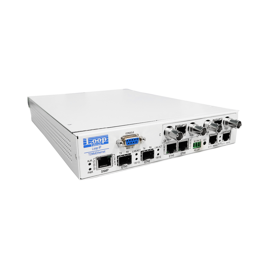
Summary of Contents for Loop Telecom Loop-IP6704A
- Page 1 Loop-IP6704A TDMoEthernet User’s Manual Loop Telecommunication International, Inc. 6F, Number 8, Hsin Ann Rd., Hsinchu Science Park, Hsinchu, 300092 Taiwan Tel: +886-3-5787696 Fax: +886-3-5646272...
- Page 2 2020 Loop Telecommunication International, Inc. All rights reserved. Version 10 June, 2020...
- Page 3 IP6704A Disclaimers Manufacturer assumes no responsibility for any damage or loss resulting from the use of this manual. Manufacturer assumes no responsibility for any loss or claims by third parties that may arise through the use of this product. III. Manufacturer assumes no responsibility for any damage or loss caused by incorrect use of this product.
- Page 4 IP6704A Bitte führen Sie das Gerät am Ende seinerLewbensdauer den zue Verfügung stehended Rückgabeund Sammelsystemen zu. At the end of the product's useful life, please dispose of it at appropriate collection points provided in y our country Une fois le produit en fin devie, veuillez le déposer dans un point de recyclage approprié.
-
Page 5: Précautions
IP6704A CAUTION: Only qualified service personnel shall install and maintain the system. This equipment must be connected to an earth socket-outlet, which has a permanent connection to protective earth with a cross-sectional area of not less than 2.5 mm ... -
Page 6: Table Of Contents
IP6704A Table of Content CAUTION: ............................III PRÉ CAUTIONS : ........................... III PRODUCT DESCRIPTION ....................15 1.1. Description ........................ 15 1.2. Features........................15 1.3. Applications ......................17 1.4. Specifications ......................18 SERIAL TRIBUTARY INTERFACE ..................... 18 MANAGEMENT AND ADMINISTRATION ..................4 INSTALLATION ........................ - Page 7 IP6704A 4.2.1. E1/T1 Line Loopback..................29 4.2.2. LS-Optical Fiber Line Loopback ............... 30 TERMINAL OPERATION ....................31 5.1. Log on ........................34 5.2. System Setup ......................35 5.2.1. Config Setup ..................... 36 5.2.2. SNMP Setup ..................... 37 5.2.2.1. SNMP System Setup ................37 5.2.2.2.
- Page 8 IP6704A 5.8. ALS/APSD Setup ..................... 66 5.9. Store/Retrieve Configuration..................66 5.10. System Display ......................67 5.10.1. Config Display ....................67 5.10.2. SNMP Display ....................68 5.10.3. System Info Display ..................68 5.10.4. Switch Display ....................69 5.10.4.1. RSTP Display ..................69 5.10.4.2.
- Page 9 IP6704A 5.17.1.7. Port 1-Hour Perf. Report ..............92 5.17.1.8. Port 24-Hour Perf. Report ..............93 5.17.1.9. Port Line Availability ................94 5.17.1.10. Port Configuration................95 5.17.1.11. Port Status ..................95 5.17.1.12. Port Alarm History ................96 5.17.2. T1 Sub-Menu ....................96 5.17.2.1.
- Page 10 IP6704A 5.21.3.3. Port System Setup ................115 5.21.3.4. Port Clear Alarm Queue & History Setup ......... 115 5.21.3.5. File Transfer ..................115 5.21.4. RS232 ......................116 5.21.4.1. Port Loopback Setup ................. 116 5.21.4.2. Port Alarm Setup ................117 5.21.4.3. Port System Setup ................117 5.21.4.4.
- Page 11 IP6704A 5.21.6.12. Port Clear Alarm Queue & History ..........133 5.21.6.13. Download Firmware ................ 134 5.21.7. QFXS ......................134 5.21.7.1. Card Setup ..................134 5.21.7.2. Card Diagnostic ................. 135 5.21.7.3. Download Firmware................135 5.21.7.4. Display Card Config................135 5.21.7.5. Card Status ..................136 5.21.8.
- Page 12 IP6704A 5.21.12.5. Port Alarm Setup ................146 5.21.12.6. Port Alarm History ................147 5.21.12.7. Clear Card Alarm History ..............147 5.21.12.8. Port 1-Hour Perf. Report ..............147 5.21.12.9. Port 24-Hour Perf. Report ............... 148 5.21.12.10. Clear Card Performance Data ............149 5.21.12.11.
- Page 13 IP6704A 10.3.1.2. 4WIRE, SIDE B, TYPE I ..............182 10.3.1.3. 4WIRE, SIDE B, TYPE II ..............183 10.3.1.4. 4WIRE, SIDE B, TYPE III ..............184 10.3.1.5. 4WIRE, SIDE B, TYPE IV ..............185 10.3.1.6. 4WIRE, SIDE B, TYPE V ..............186 10.4.
- Page 14 IP6704A Figure 2-12 Connector of the Daughter Card ................19 Figure 2-13 Match the Pin Headers to the Connector..............19 Figure 2-14 Insert Screws on the Daughter Card................. 20 Figure 2-15 Insert Screws on the Frontal Panel ................20 Figure 2-16 Top View of IP6704A ....................20 Figure 3-1 LED View of Quad E&M Voice Card Panel ..............
- Page 15 IP6704A TABLE 3-1 CONSOLE PORT SETTING ..................22 TABLE 3-2 ALARM DEFAULT – FOR SYSTEM AND LINE ............22 TABLE 3-3 PERFORMANCE PARAMETER LIST – LINE ............23 TABLE 3-4 PERFORMANCE REPORT OPTIONS ..............23 TABLE 3-5 LED INDICATION FOR MAIN UNIT ................23 TABLE 3-6 QUAD E&M LED DESCRIPTION ................
- Page 16 IP6704A TABLE 5-29 SNTP SETUP ......................66 TABLE 5-30 ALS/APSDSETUP ....................66 TABLE 5-31 PORT SETUP ......................89 TABLE 5-32 DEFINING PARAMETERS IN PORT SETUP ............89 TABLE 5-33 PORT ALARM SETUP ..................... 91 TABLE 5-34 BERT TEST ......................91 TABLE 5-35 PORT SETUP ......................
-
Page 17: Product Description
PRODUCT DESCRIPTION 1.1. Description The Loop-IP6704A TDMoEthernet is an ideal solution for service providers to build their network and achieve a fast return on investment. Currently providers need to transport both TDM and Packet traffic. These can be achieved using the E1/T1 and Gigabit Ethernet tributary ports of the IP6704A. - Page 18 IP6704A – Up to two single port DTE modules: X.21 or RS232/V.24 or V.35 or EIA530 – Up to 2 voice modules: Four ports E&M Four ports FXS Four ports FXO Four ports Magneto* Supports Echo Cancellation* –...
-
Page 19: Applications
IP6704A 1.3. Applications Service Copper/ Copper/ Unframed provider Unframed Optical Optical E1/T1 E1/T1 Pseudowire SAToP SAToP IP6704A TDMoEthernet #1 IP6704A TDMoEthernet #2 LAN1 LAN1 LAN2/ LAN2 LAN Data SNMP LAN Data Service Service Figure 1-1 IP6704A Point-to-Point Application IP6704A #2 Port Pseudowire #1 1*E1/T1... -
Page 20: Specifications
IP6704A 1.4. Specifications E1 Tributary Interface Module Line Rate 2.048 Mbps ± 50 ppm Line Code HDB3 / AMI Framing ITU G.704 (CRC: on/off, CAS: on/off, unframed) Output Signal ITU G.703 Input Signal ITU G.703 Jitter ITU G.823 Connector RJ48C T1 Tributary Interface Module Line Rate 1.544 Mbps ±... - Page 21 Chapter 1 Product Description IP6704A TDMoEthernet Voice Card (QEMA) Connector One 44-pin connector, adaptor cable included for 4 RJ45 connectors. Alarm Conditioning CGA busy after 2.5 seconds of LOS, LOF A-law or -law, user selectable as a group Encoding Impedance Balanced 600 or 900ohms Gain Adjustment -10 to +7 dB / 0.1dB step for transmit (D/A) gain...
- Page 22 Chapter 1 Product Description IP6704A TDMoEthernet 1800 Loop Resistance > 1M impedance (ON-HOOK) 235 @ 25mA feed impedance(OFF-H OOK) 90 @ 100mA feed Support 2 REN per port (1 REN = 6930 + 8 F) FXS Ringing 20 Hz, other frequencies: 16.7Hz, 25 Hz, 50Hz (Jump selectable) 78 Vrms (sine wave) (45 Vrms to 86 Vrms wide range by Resistor...
- Page 23 Chapter 1 Product Description IP6704A TDMoEthernet C37.94 Interface 820nm Ordering Code Mode Data Rate (Mb/s) ZRATT 1*8 Multi-Mode Wavelength (nm) Distance (km) Connector TX Power (dBm Peak) RX Power (dBm Peak) Note MIN. TYP. MAX. Wavelength MIN. TYP. MAX. Wavelength -19.8 --- -12.8 792/820/865 --- 50/125μm Fiber...
-
Page 24: Management And Administration
Chapter 1 Product Description IP6704A TDMoEthernet Ordering Code Mode Data Rate (Mb/s) QFBTT 1*9 Multi-Mode 125M Wavelength (nm) Distance (km) Connector 1310 TX Power (dBm) RX Power (dBm) Note MIN. TYP. MAX. Wavelength MIN. TYP. MAX. Wavelength 1270/1310/1380 --- 1260/---/1610 Output Optical Power 62.5/125 μm fiber... - Page 25 Chapter 1 Product Description IP6704A TDMoEthernet Physical and Environmental Dimensions(W x H x D) 213 mm x 41 mm x 290 mm (8.39" x 1.61" x 11.42") Temperature 0°C to +75°C 0% to 95% RH (non-condensing) Humidity Mounting Desktop stackable, rack mount, wall mount Cooling It is fanless unit Standards Compliance...
-
Page 26: Installation
The following list indicates a site selection guideline. Users need to follow this guideline to select a proper installation site. Location of the Loop-IP6704A unit should be part of the central office equipment layout design. Considerations should be given to entrance cable routing. -
Page 27: Figure 2-2 Rear Panel View
Chapter 2 Installation IP6704A TDMoEthernet Figure 2-2 Rear Panel View Figure 2-3 Rear Panel View P9 Power Chassis Grounding The chassis is grounded when rack mounted. However, for stand-alone units or extra grounding protection for rack mounted units, a dedicated chassis ground screw and lock washer is provided. -
Page 28: Pin Assignment Information
Chapter 2 Installation IP6704A TDMoEthernet 2.3. Pin Assignment Information Table 2-1 DB9S Console Port Pin Assignment Pin Number Signal Description Data Carrier Detect To DTE Receive Data To DTE Transmit Data From DTE Unassigned Signal Ground Data Set Ready To DTE Unassigned Clear to send To DTE... -
Page 29: Table 2-7 V.35/Db25 Dte Port Pin Definition
Chapter 2 Installation IP6704A TDMoEthernet No Connection No Connection Receive Data - Input to IP6704A No Connection No Connection The DTE port is configured as a serial device. There are 5 different DTE boards: V.35/DB25, EIA530/DB25, X.21/DB15, RS449/DB37 and RS422. Pin definitions are defined in Table 2-9 to 2-16. -
Page 30: Table 2-8 Eia530/Db25 Dte Port Pin Definition
Chapter 2 Installation IP6704A TDMoEthernet Table 2-8 EIA530/DB25 DTE Port Pin Definition Pin Number Signal Source Cable Shield Transmit Data Receive Data Request To Send Clear To Send Data Set Ready Signal Ground Data Carrier Detect Receive Clock Return Data Carrier Detect Return External Clock Return Transmit Clock Return Clear To Send Return... -
Page 31: Table 2-10 Rs449/Db37 Dte Port Pin Definition
Chapter 2 Installation IP6704A TDMoEthernet Control Return Receive Data Return Indication Return Signal Timing Return External Clock Return Unassigned Table 2-10 RS449/DB37 DTE Port Pin Definition Pin Number Signal Source Cable Shield Unassigned Unassigned Transmit Data Transmit Clock Receive Data Request To Send Receive Clock Clear To Send... -
Page 32: Table 2-11 Rs422 Dte Port Pin Definition
Chapter 2 Installation IP6704A TDMoEthernet Data Terminal Ready Return Data Carrier Detect Return Unassigned Unassigned Unassigned External Clock Return Unassigned Unassigned Table 2-11 RS422 DTE Port Pin Definition Pin Number Signal Source Cable Shield Transmit Data Receive Data Request To Send Clear To Send Data Set Ready Signal Ground... -
Page 33: Figure 2-5 E&M/Db44 Connector Pin Assignment
Chapter 2 Installation IP6704A TDMoEthernet Table 2-12 Pin Assignment for QFXS/ QFXO RJ11 FXS Line Power FXO Pin Volt Voice Ports Pin No. Name Normal Tip Open (option) Loop Start GND Start (option) Pin 3 Ring Loop Pin 4 Open Open Pin 3 Ring... -
Page 34: Table 2-15 Pin Assignment For E&M/Db44 With Rj45 Connector Ch3
Chapter 2 Installation IP6704A TDMoEthernet White/ Blue TIP 1 Green White/ Brown Brown Table 2-15 Pin Assignment for E&M/DB44 with RJ45 Connector CH3 DB44 Connector RJ45 Connector CH3 Pin Number Pin Name Pin Number Color White/ Orange Orange RING 1 White/ Green RING Blue... -
Page 35: Figure 2-6 Jumper Locations For Port A Port B E1/T1
Chapter 2 Installation IP6704A TDMoEthernet NOTES: You should do ACO HW load default after you changed the E1/T1 mode. Figure 2-6 Jumper Locations for Port A Port B E1/T1 JUM9 JUM9 JUM2 JUM2 JUM4 JUM4 JUM1 JUM3 JUM1 JUM3 JUM10 JUM10 JUM5 JUM5... -
Page 36: Default Setting
Chapter 2 Installation IP6704A TDMoEthernet 2.4. Default Setting Table 2-18 Default Software Configuration Configuration Option Default Frame ON, OFF,CAS,CRC, CAS+CRC Code HDB3, AMI HDB3 120 OHM INTF 120 OHM, 75OHM E1 Line ON, OFF ON, OFF IDLE CODE 00-FF BUSY,IDLE BUSY Frame D4, None, ESF, ESF &... -
Page 37: Cold-Swappable Steps
Chapter 2 Installation IP6704A TDMoEthernet 2.5. Cold-swappable steps 2.5.1. Power off IP6704A is not hot-swappable. Therefore, if tributary modules are needed to change or remove, please carefully power off first. 2.5.2. Open the case Use a normal Philips screwdriver to remove the five screws on top of the chassis. After the five screws are removed, the top case can be removed easily. -
Page 38: Figure 2-9 Inside Ip6704A
Chapter 2 Installation IP6704A TDMoEthernet Figure 2-9 Inside IP6704A And then turn to the frontal panel. Remove the two screws on the daughter card’s own panel. After removing the two screws, carefully take off the frontal panel of the daughter card. -
Page 39: Install The Tributary Module
Chapter 2 Installation IP6704A TDMoEthernet After the procedures above are properly operated, look into the end of the card. You can see a black connector and a set of pin headers which connect the daughter card to the main card. The connector is marked with red circle in the following figure. Unplugged the connector and the whole daughter card can be removed from the chassis. -
Page 40: Close The Case
Chapter 2 Installation IP6704A TDMoEthernet Figure 2-14 Insert Screws on the Daughter Card Turn to the frontal panel and put on the daughter card’s own coherent panel. And then insert the two screws properly. Figure 2-15 Insert Screws on the Frontal Panel 2.5.5. -
Page 41: Operation
Chapter 3 Operation IP6704A TDMoEthernet OPERATION 3.1. Power On Turn power on by attaching power cable at the rear of the unit. Return to Default Setting. The unit is shipped with factory default setting. 3.2. Self-Test If password is enabled, users must enter the password when logging in to gain the privilege to change system configurations on the terminal. -
Page 42: System Configuration
NONE 3.6. Alarm When the Loop-IP6704A reports an alarm condition, such as loss of synchronization, the alarm will cause the LED on the front panel to light. Each alarm can be individually enabled or disabled. The alarm types are listed in the table as below. -
Page 43: Report
IP6704A TDMoEthernet 3.7. Report For E1/T1 line receiver, Loop-IP6704A has two sets of performance registers. These are line and user. The line performance register tracks the E1/T1 line receiver performance status. The user performance register tracks the E1/T1 line receiver as well, but user may clear at any time. -
Page 44: Figure 3-1 Led View Of Quad E&M Voice Card Panel
Chapter 3 Operation IP6704A TDMoEthernet Flashing Active. Data is being transmitted or received through the Green Ethernet port. SNMP 10Mbps Electrical 10/100/10 Amber 100Mbps Green 1000Mbps 100Mbps 100/1000 Green 1000Mbps No LOS detected Alarm: Detected loss of E1/T1 signal E1/T1 Flashing Loopback or Bert active Green... -
Page 45: Table 3-6 Quad E&M Led Description
Chapter 3 Operation IP6704A TDMoEthernet Table 3-6 Quad E&M LED Description NOTES: In the following table, we take port 1 as an example. Standard DESCRIPTION Alarm Port 4 Port 3 Port 2 Port 1 G-LED) = pay attention to changes in Green LED only Y-LED) = pay attention to changes in Yellow LED Green... -
Page 46: Table 3-7 Led Indication For Single E1
Chapter 3 Operation IP6704A TDMoEthernet Alarm R-LED) The red light is on while the other lights are off, meaning alarm resulting from No Mapping or Los LOF happens in all of the ports. R-LED) ( Y-LED) The red light along with the yellow one are on while the four green lights are off, meaning the Quad E&M Card is TX only type with the occurrences of No Mapping or Los LOF. -
Page 47: Figure 3-3 Led View Of Qfxsa Voice Card
Chapter 3 Operation IP6704A TDMoEthernet Quad FXSA Card (Bottom Side) (YELLOW) (GREEN) (RED) (YELLOW) - GM (RED) - ALM LED Indicators Figure 3-3 LED View of QFXSA Voice Card Table 3-8 LED Indicator Lights for QFXSA Card Port 4 Port 3 Port 2 Port 1 Description Yellow Green/Yellow/Red... -
Page 48: Management Port (Ethernet Port)
Chapter 3 Operation IP6704A TDMoEthernet Table 3-10 LED Indicator Lights for the LS-Optical Fiber Card Color Indication Flashing Green Activation UNSYNC Green SYNC Yellow Receive Alarm Flashing Yellow Loopback 3.9. Management Port (Ethernet Port) As two IP6704A are connected: one is set as local unit and the other is set as remote unit. See also the following diagram. -
Page 49: Maintenance
MAINTENANCE 4.1. Self-Test When the Loop-IP6704A is powered up, a complete self-test routine is run to check all I/O ports, read/write memory, and data paths to validate system integrity. During system self-test, "TESTING" message and testing code are shown on the VT100 terminal screen. -
Page 50: Ls-Optical Fiber Line Loopback
Chapter 4 Maintenance IP6704A TDMoEthernet 4.2.2. LS-Optical Fiber Line Loopback LS-Optical Fiber Line Loopback Local Loopback Payload Loopback Figure 4-2 Loopback Block Diagram Loop Telecommunication International, Inc. -
Page 51: Terminal Operation
On each screen, the available commands and the configurable fields are highlighted. When a VT-100 terminal is connected to the CONSOLE port of the Loop-IP6704A, a main menu is displayed on the VT-100 monitor. The main menu consists of four groups of commands, DISPLAY, LOG, SETUP, and MISC. -
Page 52: Figure 5-2 Vt-100 Setup Menu Overview
Chapter 5 Terminal Operation IP6704A TDMoEthernet VT100 [Setup] S→System T → Bundle Setup K → Clock Source Setup W → Firmware Transfer A → Config Setup A → Bundle IP setup A → Class of Service A → Download Firmware →... -
Page 53: Figure 5-4 T1 Vt-100 E1/T1 Menu Tree
Chapter 5 Terminal Operation IP6704A TDMoEthernet [DISPLAY] 1 → Port 1-Hour Perf . Report 2 → Port 24-Hour Perf . Report A → Port Line Availability C → Port Configuration I → Port Status H → Port Alarm History [SETUP] S →... -
Page 54: Log On
IP6704A TDMoEthernet 5.1. Log on When the Loop-IP6704A is powered on, the screen will show as below. If the terminal screen is illegible, press the Enter and Esc key alternatively to bring up the main menu. This is particularly needed if the terminal is connected to the controller while the power is already applied. -
Page 55: System Setup
Chapter 5 Terminal Operation IP6704A TDMoEthernet After logon, the main menu will appear as shown below. IP67 04 A === Ma in Men u == = 12 :21 :21 01 /18 /20 16 Seri al Num ber De vic e Na me : I P67 04 A (T CXO ) Hard war e V ers ion : V er. -
Page 56: Config Setup
Chapter 5 Terminal Operation IP6704A TDMoEthernet 5.2.1. Config Setup The full menu path for Config Setup is as follows: O > Logon S > System Setup A > Config Setup The screen of Config Setup will show as below. IP67 04 A = == Con fig Se tup === 12 :14 :13 01 /18 /20 16 ARRO W K EYS : C URS OR MOV E, Pl e ase In put : h h:m m:ss mm /dd /yy yy, BA CKS PAC E t o e dit... -
Page 57: Snmp Setup
Chapter 5 Terminal Operation IP6704A TDMoEthernet 5.2.2. SNMP Setup The full menu path for SNMP Setup is as follows: O > Logon S > System Setup B > SNMP Setup The screen of SNMP Setup will show as below. IP67 04A E1 = == SNM P S etu p == = 12: 35: 31 01/ 18/ 201 6 A ->... -
Page 58: V1: Trap Setup
Chapter 5 Terminal Operation IP6704A TDMoEthernet 5.2.2.2. V1: Trap Setup The full menu path for V1: Trap Setup is as follows: O > Logon S > System Setup B > SNMP Setup B > V1: Trap Setup The screen of V1: Trap Setup will show as below IP67 04A E1 = == Tra p S etu p == = 12: 48: 51 01/ 18/ 201 6... -
Page 59: V3: View-Based Access Control Model Setup 1
Chapter 5 Terminal Operation IP6704A TDMoEthernet Priv Pr oto col : D ES Priv Ke y : 9 9E3 9FE 117 483 437 C4D 153 D9C 958 8D23 Stat us : A cti ve Stor age : N onV ola til e <<... -
Page 60: V3: Target & Notify Setup
Chapter 5 Terminal Operation IP6704A TDMoEthernet Writ e V iew Na me : t wo Noti fy Vie w N ame : ( res erv ed) Stat us : A cti ve Stor age : N onV ola til e [Vie w F ami ly] 1/ 1 View Na me : t wo Sub- tre e... -
Page 61: Rstp Setup
Chapter 5 Terminal Operation IP6704A TDMoEthernet IP67 04A T1 == = S wit ch Set up = == 11: 29: 41 01/ 23/ 201 6 A -> RST P S etu p B -> QOS Se tup C -> Vla n S etu p D ->... -
Page 62: Table 5-4 Rstp Setup
Chapter 5 Terminal Operation IP6704A TDMoEthernet The RSTP Enabled screen: IP67 04A T1 = == RST P S etu p == = 11: 39: 27 01/ 23/ 201 6 ARRO W K EYS : C URS OR MOV E, TAB : R OLL OP TIO NS RSTP : R STP Desi gna ted Ro ot MAC AD DR: B7 :DC :00 :56 :B7 :E4 Desi gna ted Ro ot Pri ori ty: 0... -
Page 63: Table 5-6 Eth Setup (With Stp Selected)
Chapter 5 Terminal Operation IP6704A TDMoEthernet Table 5-6 ETH Setup (with STP selected) Field Setting Options Default Setting Cost 0 ~ 65535 00000 Prio 0 ~ 240 The ETH screen when RSTP is selected: IP67 04 A === RS TP Set up = == 15 :27 :21 01 /18 /20 16 ARRO W K EYS : C URS OR MOV E, Ple ase In put : 0 ~65 535, BA CKS PAC E t o e dit Por t... -
Page 64: Qos Setup
Chapter 5 Terminal Operation IP6704A TDMoEthernet 5.2.3.2. QOS Setup The full menu path for QOS Setup is as follows: O > Logon S > System Setup C > Switch Setup B > QOS Setup The screen of QOS Setup will show as below. IP67 04 A === Qo S S etu p == = 12 :25 :47 01 /18 /20 16... -
Page 65: Table 5-8 Priority Mode Setup
Chapter 5 Terminal Operation IP6704A TDMoEthernet Table 5-8 Priority Mode Setup Field Setting Options Default Setting SNMP ETH1 ETH2 CoS, ToS, DSCP, Fixed ETH3 ETH4 B > Fixed Priority Setup The screen of Fixed Priority Setup will show as below. IP67 04 A == = F ixe d P rio rit y Se tup == = 12 :32 :09 01 /18 /20 16... -
Page 66: Table 5-11 Tos Field Priority Setup
Chapter 5 Terminal Operation IP6704A TDMoEthernet D > ToS Field Priority Setup The screen of ToS Field Priority Setup will show as below. IP67 04 A = == ToS Fi eld Pr ior ity Set up === 12 :33 :29 01 /18 /20 16 ARRO W K E YS : CUR SOR MO VE , E NTE R K EY : I TEM SEL ECT Tos pri ori ty Q ueu e... -
Page 67: Table 5-12 Scheduling Algorithm
Chapter 5 Terminal Operation IP6704A TDMoEthernet A > Scheduling Algorithm The screen of Scheduling Algorithm will show as below. IP67 04 A == = S che dul ing Al gori thm == = 12 :35 :42 01 /18 /20 16 ARRO W K EYS : CUR SOR MO VE , E NTE R K EY : I TEM SEL ECT port Q ueu e... -
Page 68: Vlan Setup
Chapter 5 Terminal Operation IP6704A TDMoEthernet 5.2.3.3. Vlan Setup The full menu path for Vlan Setup is as follows: O > Logon S > System Setup C > Switch Setup C > Vlan Setup The screen of Vlan Setup will show as below. IP67 04 A === VL AN Set up = == 12 :37 :53 01 /18 /20 16... -
Page 69: Table 5-14 Vlan Configuration Setup
Chapter 5 Terminal Operation IP6704A TDMoEthernet VLANID=2~4094 IP67 04 A = == VLA N C onf igu rat ion Set up === 12 :06 :15 01 /18 /20 16 ARRO W K EYS : C URS OR MOV E, TAB : R OLL OP TIO NS VLAN ID : 000 2 VLAN : Dis abl e... -
Page 70: Port Speed Setup
Chapter 5 Terminal Operation IP6704A TDMoEthernet 5.2.3.3.2. VLAN Port Setup The full menu path for Vlan Port Setup is as follows: O > Logon S > System Setup C > Switch Setup C > Vlan Setup B > VLAN Port Setup The screen of Vlan Port Setup will show as below. -
Page 71: Password Setup
Chapter 5 Terminal Operation IP6704A TDMoEthernet Logi cal Et her net Po rt Iso lat ion SN MP ETH 1 E TH2 ET H3 ETH4 MG MT Grou p 1 : Ye s Ye s Grou p 2 : No Y es Ye s Grou p 3... -
Page 72: Static Route Setup
Chapter 5 Terminal Operation IP6704A TDMoEthernet 5.2.5. Static Route Setup The full menu path for Static Route Setup is as follows: O > Logon S > System Setup E >Static Route Setup The screen of Static Route Setup will show as below. IP67 04 A = == Sta tic Ro ute Set up === 12 :49 :35 01 /18 /20 16... -
Page 73: Ssh Setup
Chapter 5 Terminal Operation IP6704A TDMoEthernet PC (Remote) Gateway IP6704A(Local) IP: 10.1.1.1 11.1.254.254 Gateway: 10.1.254.254 SNMP Internet ETH1 ETH2 ETH3 Figure 5-5 Static Route Setup 5.2.6. SSH Setup The full menu path for SSH Setup is as follows: O > Logon S >... -
Page 74: Radius Setup
Chapter 5 Terminal Operation IP6704A TDMoEthernet 5.2.7. RADIUS Setup The full menu path for RADIUS Setup is as follows: O > Logon S > System Setup G > RADIUS Setup IP6704A E1 === RADIUS setup === 08:55:35 01/19/2016 ARROW KEYS: CURSOR MOVE, TAB: ROLL OPTIONS Server1 : DISABLE IP: 000.000.000.000 Key (Secret):... -
Page 75: Bundle Ip Setup
Chapter 5 Terminal Operation IP6704A TDMoEthernet 5.3.1. Bundle IP Setup The full menu path for Bundle IP Setup is as follows: O > Logon T > Bundle Setup A >Bundle IP Setup The screen of Bundle IP Setup will show as below. IP67 04 A === Bu ndl e IP Se tup === 12: 42: 41 0 1/1 8/2 016... -
Page 76: Bundle Link Setup
Chapter 5 Terminal Operation IP6704A TDMoEthernet 5.3.3. Bundle Link Setup The full menu path for Bundle Link setup is as follows: O > Logon T > Bundle Setup C > Bundle Link Setup CESoPSN P670 4 = == Bu ndl e L ink Se tup == = 1 2:5 7:1 0 0 1/1 8/2 016 ARRO W K EYS : C URS OR MOV E, TAB : R OLL OP TIO NS... - Page 77 Chapter 5 Terminal Operation IP6704A TDMoEthernet Encap. Type Unframe SAToP SAToP Frame CESoPSN CESoPSN CESoETH 0 ~ 255 Dst UDP Num 2142 2142 Src UDP CESoPSN 1 ~ 65535 00001 Num(ECID) SAToP CESoETH 1 ~ 1048575 00001 Dest. IP CESoPSN Enter the destination IP address 000.000.000.000 (Dest.
- Page 78 Chapter 5 Terminal Operation IP6704A TDMoEthernet IP6704A IP6704A ACR Clock network Line Clock Stratum 1 IP6704A IP6704A ANT20 ACR Clock Line Clock Stratum 2 IP6704A IP6704A Internal ACR Clock Clock Stratum 3 LOOP-E500 IP6704A IP6704A Internal ACR Clock Line Clock Clock Stratum 4 Figure 5-6 Stratum Setting...
-
Page 79: Acr Timestamp Setup
Chapter 5 Terminal Operation IP6704A TDMoEthernet 5.3.4. ACR TimeStamp Setup Adaptive Clock Recovery (ACR) is a process that negates the effect of random packet delay variation and captures the average rate of transmission of the original bit stream. ACR recovers the original clock for a synchronous data stream from the actual payload of the data stream. -
Page 80: Download Firmware
Chapter 5 Terminal Operation IP6704A TDMoEthernet The screen of Firmware Transfer will show as below. IP67 04 A === Fir mwa re T r ansf er = = 13: 00: 39 0 1/1 8/2 016 A -> Do wnl oad Fi rmw are B ->... -
Page 81: Download Configuration
Chapter 5 Terminal Operation IP6704A TDMoEthernet IP67 04 A === Do wnl oad Boo t S trap per == = 13: 04: 03 0 1/1 8/2 016 ARRO W K EYS : C URS OR MOV E, Ple ase In put : n nn. nnn. nnn .nn n, BAC KSP ACE to ed it Stra ppe r V ers ion : V1 .01 .01 10 /08 / 20 15 TFTP Se rve r I P... -
Page 82: Boot Bank Change
Chapter 5 Terminal Operation IP6704A TDMoEthernet IP67 04 A == = Up loa d Co nfi g urat ion === 13: 07: 20 0 1/1 8/2 016 ARRO W K EYS : C URS OR MOV E, Ple ase In put : n nn. nnn. nnn .nn n, BAC KSP ACE to ed it TFTP Se rve r I P : 00 0.0 00. -
Page 83: Clock Source Setup
Chapter 5 Terminal Operation IP6704A TDMoEthernet K > Clock Source Setup The screen of Clock Source Setup will show as below. IP67 04A T1 = == Clo ck So urc e Setu p = == 13: 09: 06 01 /18 /20 16 A - >... -
Page 84: Synce Clock Setup
Chapter 5 Terminal Operation IP6704A TDMoEthernet Field Setting Options Default Setting Port A, B, C, D ACR1~4 0 ~ 15 Enable ON, OFF 5.5.2. SyncE Clock Setup The full menu path for Clock Source Setup is as follows: O > Logon K >... -
Page 85: Sntp Setup
Chapter 5 Terminal Operation IP6704A TDMoEthernet Ethe rne t L ink DIS ABL E L-Bi t DIS ABL E R-Bi t DIS A BL E MAC Cha nge DIS ABL E Warm Re sta rt DIS ABL E Over Run DIS ABL E Unde rRu n DIS ABL E... -
Page 86: Als/Apsd Setup
Chapter 5 Terminal Operation IP6704A TDMoEthernet Table 5-29 SNTP Setup Field Setting Options Default Setting SNMP ON/OFF ON, OFF SNMP Server 1 000.000.000.000 000 ~ 255 SNMP Server 2 000.000.000.000 SNMP timezone +0, +1~+12, -1~-12 5.8. ALS/APSD Setup The full menu path for ALS/APSD Setup is as follows: O >... -
Page 87: System Display
Chapter 5 Terminal Operation IP6704A TDMoEthernet 5.10. System Display The full menu path for System Display is as follows: O > Logon C > System Display The screen of System Display will show as below. IP67 04 A == = Sy ste m Di s play === 13: 15: 22 0 1/1 8/2 016 A ->... -
Page 88: Snmp Display
Chapter 5 Terminal Operation IP6704A TDMoEthernet 5.10.2. SNMP Display The full menu path for SNMP Display is as follows: O > Logon C > System Display B > SNMP Display The screen of SNMP Display will show as below. IP67 04A E1 == = S NMP Di spl ay = == 13: 25: 30 01/ 18/ 201 6 Devi ce Na m e... -
Page 89: Switch Display
Chapter 5 Terminal Operation IP6704A TDMoEthernet 5.10.4. Switch Display The full menu path for Switch Display is as follows: O > Logon C > System Display D > Switch Display The screen of Switch Display will show as below. IP67 04A T1 === Sw itc h D isp lay === 12: 58: 28 01/ 23/ 201 6 A ->... -
Page 90: Qos Display
Chapter 5 Terminal Operation IP6704A TDMoEthernet 5.10.4.2. QOS Display The full menu path for QOS Display is as follows: O > Logon C > System Display D > Switch Display B > QOS Display The screen of QOS Display will show as below. IP67 04 A = == Q oS D isp l ay == = 12: 02: 50 0 1/1 8/2 016... - Page 91 Chapter 5 Terminal Operation IP6704A TDMoEthernet A > Priority Mode The screen of Priority Mode will show as below IP67 04 A === Pri ori ty M od e === 12 :12 :05 01/ 18/ 201 6 SNMP : C oS ETH1 : C oS ETH2 : C oS ETH3 : C oS...
- Page 92 Chapter 5 Terminal Operation IP6704A TDMoEthernet IP67 04 A == = Vl an C oS Pri or ity = == 12 :13 :34 01/ 18/ 201 6 Cos pri ori ty Q ueu e The ord eri ng of que ue pri ori ty is giv en by: Que ue 3(P 3) >...
- Page 93 Chapter 5 Terminal Operation IP6704A TDMoEthernet IP67 04 A === S che dul in g = == 12 :16 :40 0 1/1 8/2 016 A -> Sc hed uli ng Alg orit hm B -> WR R W eig ht <<...
-
Page 94: Vlan Display
Chapter 5 Terminal Operation IP6704A TDMoEthernet IP67 04 A = == W RR W eig ht === 12 :18 :41 01/ 18/ 201 6 P 0 q ueu e P1 qu eue P2 que ue P3 qu eue WRR Wei ght : 7 Note : P 3 Q ueu e m ust be no n -z ero to tr ans mit PW (bu ndl e) pac ket s f rom TD M. -
Page 95: Port Speed Display
Chapter 5 Terminal Operation IP6704A TDMoEthernet IP67 04 A == = VL AN C onf igu rat i on Di spl ay= == 13: 16: 29 0 1/1 8/2 016 ARRO W K EYS : C URS OR MOV E, Ple ase In put : 1 ~40 94, BAC KSP ACE to ed it VLAN ID : 000 1 <<... -
Page 96: Port Statistics
Chapter 5 Terminal Operation IP6704A TDMoEthernet The screen of Port Speed Display will show as below. IP67 04 A = == Por t Sp eed Di spla y = == 13: 37: 47 0 1/1 8/2 016 Phys ica l E the rne t P ort SNMP Sp eed : N one (L ink -Do wn) -
Page 97: Static Route Display
Chapter 5 Terminal Operation IP6704A TDMoEthernet The screen of MAC Table Display will show as below. IP67 04 A = == MAC Tab le Dis pla y == = 13: 44: 01 0 1/1 8/2 016 Inde x Nam e MA C sta te ==== === === === === === === === === === === === === === ==== === === === === === === === ===... -
Page 98: Bundle Ip Display
Chapter 5 Terminal Operation IP6704A TDMoEthernet J > Bundle Display The screen of Bundle Display will show as below. IP67 04 A == = Bun dle Di sp lay == = 13 :46 :00 01 /18 /20 16 A -> Bu ndl e I P D ispl ay B ->... -
Page 99: Bundle Link Display
Chapter 5 Terminal Operation IP6704A TDMoEthernet O > Logon J > Bundle Display B > DS0 TSlot to Bundle Display The screen of DS0 TSlot to Bundle Display will show as below. IP67 04 A === DS0 TSl ot to B und le Disp lay == = 13 :46 :50 01/ 18/ 201 6 ARRO W K EYS : C URS OR MOV E, TAB : R OLL OP TIO NS Port : A... -
Page 100: Bundle Summary
Chapter 5 Terminal Operation IP6704A TDMoEthernet 5.11.4. Bundle Summary The full menu path for Bundle Summary is as follows: O > Logon J > Bundle Display D> Bundle Summary The screen of Bundle Summary will show as below. IP67 04 A = == B und l e Sum mar y == = 13: 47: 59 01/1 8/2 016... -
Page 101: Bundle Arp Status Display
Chapter 5 Terminal Operation IP6704A TDMoEthernet IP6704A T1 === Bundle Status === 16:39:36 01/22/2016 Po BID Jit-Buf Jit-Buf Jit-Buf L-Bit R-Bit Tx-Good Rx-Good RxLost Link Size UR / OR Min/Max Depth == === === === === === ======= ===== ===== ========= ========= ====== ==== ==== 19 19 19 19 19 19... -
Page 102: Bundle Ping Status Display
Chapter 5 Terminal Operation IP6704A TDMoEthernet IP6704A T1 === Bundle ARP Status Display === 15:28:48 01/22/2016 ARP Path ============================= IP Address :000.000.000.000 MAC Address:00:50:C6:0F:B7:6F RX-ARP TX-ARP TX-ARP RX-ARP Bdl Src. IP Address Src. MAC Address VLAN VLAN REQ REPLY REPLY =============== ================= ==== ==== ======= ======= ======= ======= === <<... -
Page 103: Ip Conflict
Chapter 5 Terminal Operation IP6704A TDMoEthernet IP6704A T1 === Bundle PING Status Display === 15:34:39 01/22/2016 PING Path ============================= IP Address :000.000.000.000 MAC Address:00:50:C6:0F:B7:6F RX-PING TX-PING TX-PING RX-PING Bdl Src. IP Address Src. MAC Address VLAN VLAN REQ REPLY REPLY =============== ================= ==== ==== ======= ======= ======= ======= === <<... -
Page 104: Clock Source Display
Chapter 5 Terminal Operation IP6704A TDMoEthernet 5.12. Clock Source Display The full menu path for Clock Source Display is as follows: O > Logon IP67 04 A === Ma in Me nu == = 13: 49: 30 01 /18 /20 16 Seri al Num ber De vic e Na me : I P67 04 A (T CXO ) Hard war e V ers ion : V er. -
Page 105: Synce Clock Display
Chapter 5 Terminal Operation IP6704A TDMoEthernet IP67 04 A == = Clo ck S our ce D ispl ay = == 13 :49 :46 01/ 18/ 201 6 Mast er_ Clk So urc e : IN TER NAL Seco nd_ Clk So urc e : IN TER NAL Curr ent Cl ock : MA STE R_C LK Clk_ Rec ove r_M ode... -
Page 106: Alarm Queue Summary
Chapter 5 Terminal Operation IP6704A TDMoEthernet 5.13. Alarm Queue Summary The full menu path for Alarm Queue Summary is as follows: O > Logon Q > Alarm Queue Summary The screen of Alarm Queue Summary will show as below. IP67 04 A == = A lar m Q ueu e S u mmar y = == 14: 05: 08 01/ 18/ 201 6 <<... -
Page 107: Sfp Status
Chapter 5 Terminal Operation IP6704A TDMoEthernet 5.15. SFP Status The full menu path for SFP Status is as follows: O > Logon G > SFP Status The screen of SFP Status will show as below. IP67 04 A === S FP Sta tu s = == 14 :07 :45 01 /18 /20 16 [--- - -- --- --- --- ET H1 --- --- --- --- --- ] [ -- - ---- --- --- -- ETH 2 - --- --- --- --- -- ]... -
Page 108: E1/T1 Sub-Menu
Chapter 5 Terminal Operation IP6704A TDMoEthernet 5.17. E1/T1 Sub-Menu 5.17.1. E1 Sub-Menu Press P to choose a port. Use the tab key to select. Press enter to apply. Now the system should be switched to the card type and the port you want. This information is indicated on the upper left corner of the screen. -
Page 109: Port Loopback Test
Chapter 5 Terminal Operation IP6704A TDMoEthernet Table 5-31 Port Setup Field Setting Options Default Setting CODE HDB3, AMI HDB3 INTF 75 OHM, 120OHM 120 OHM ON, OFF ON, OFF IDLE CODE 0 ~ 9, A ~ F BUSY, IDLE BUSY Table 5-32 Defining Parameters in Port Setup Parameters Definition... -
Page 110: Port Alarm Setup
Chapter 5 Terminal Operation IP6704A TDMoEthernet P > Choose a Port K > Clear Performance Data The screen of Clear Performance Data will show as below. E1 P ort A = == E1/ T1 Po rt === 1 4:1 9:4 1 0 1/1 8/2 016 [DIS PLA Y] [S ETU P] 1 ->... -
Page 111: Clear Alarm History
Chapter 5 Terminal Operation IP6704A TDMoEthernet Table 5-33 Port Alarm Setup Field THRESHOLD ALARM Setting Options Default Setting Options Default DISABLE DISABLE DISABLE DISABLE DISABLE, 10E-5 ~ 10E-9 10E-5 ENABLE DISABLE 001 ~ 900 DISABLE 001 ~ 900 DISABLE 001 ~ 900 DISABLE 5.17.1.5. -
Page 112: Port 1-Hour Perf. Report
Chapter 5 Terminal Operation IP6704A TDMoEthernet E1 Po rt A = == Be rt test 1 3:5 3:1 8 01/1 8/2 016 ARRO W K EYS : C URS OR MOV E, TAB : R OLL OP TIO NS Typ e : FU LL D ire ct : LI NE... -
Page 113: Port 24-Hour Perf. Report
Chapter 5 Terminal Operation IP6704A TDMoEthernet Use TAB key to select register type, USER or LINE. The current selection will be highlighted by an asterisk (*). >> S ele ct Reg ist er Typ e ? *U SER L INE After pressing ENTER from the above screen, the following screen will show up USER E1 Po rt A... -
Page 114: Port Line Availability
Chapter 5 Terminal Operation IP6704A TDMoEthernet The screen of Port 24-Hour Perf. Report will show as below. E1 Po rt A === Por t 24 - Hou r Pe rf. Repo rt == = 1 8 :3 2:1 6 01 /18 /20 16 >>... -
Page 115: Port Configuration
Chapter 5 Terminal Operation IP6704A TDMoEthernet E1 Por t A == = Por t Lin e Ava ila bili ty == = 13: 58: 48 01 /18 /20 16 -- L ine Av ail abi lit y d uri ng Las t 2 4 -H our : V ali d S eco nds : 7 128 se c on ds A vai lab le Sec ond s... -
Page 116: Port Alarm History
Chapter 5 Terminal Operation IP6704A TDMoEthernet E1 P ort A == = P ort S tat us === 1 5:0 7:1 3 0 1/1 8/2 016 -- L INE -- L OS : LOS L OF : LOF R CV AIS : NO R CV RAI : NO X MT AIS : AIS X MT RAI : NO... -
Page 117: Port Setup
Chapter 5 Terminal Operation IP6704A TDMoEthernet T1 P ort A = == E1/ T1 Po rt === 1 2:4 7:0 1 0 1/1 8/2 016 [DIS PLA Y] [S ETU P] 1 -> Po rt 1 -H our Pe rf. Re por t S ->... -
Page 118: Port Loopback Test
Chapter 5 Terminal Operation IP6704A TDMoEthernet Table 5-36 Defining Parameters in Port Setup Parameters Definition CODE For the E1 line interface, either AMI (Alternate Mark Inverting) or HDB3 (high density bipolar of length 3) line code format can be chosen, be sure this setting matches that of the network. -
Page 119: Port Alarm Setup
Chapter 5 Terminal Operation IP6704A TDMoEthernet The screen of Clear Performance Data will show as below. T1 P ort A = == E1/ T1 Po rt === 1 4:1 9:4 1 0 1/1 8/2 016 [DIS PLA Y] [S ETU P] 1 ->... -
Page 120: Clear Alarm History
Chapter 5 Terminal Operation IP6704A TDMoEthernet 001 ~ 900 DISABLE 001 ~ 900 DISABLE 001 ~ 900 DISABLE 5.17.2.5. Clear Alarm History The full menu path for Clear Alarm History is as follows: O > Logon P > Choose a Port X >... -
Page 121: Port 1-Hour Perf. Report
Chapter 5 Terminal Operation IP6704A TDMoEthernet Type=SELECT T1 Po rt A = == Be rt test 1 3:0 1:5 4 01/1 8/2 016 ARRO W K EYS : C URS OR MOV E, TAB : R OLL OP TIO NS Typ e : SE LEC T D ire ct... -
Page 122: Port 24-Hour Perf. Report
Chapter 5 Terminal Operation IP6704A TDMoEthernet T1 Po rt A === Por t 1 -H our Per f. Repo rt = == 13 :04 :35 0 1/1 8/2 016 USER -- V ali d S eco nds in Cu rre nt 15 - Min In ter val : 2 75 sec ond s ( ES) (UA S) (BE S) -
Page 123: Port Line Availability
Chapter 5 Terminal Operation IP6704A TDMoEthernet T1 Po rt A === Por t 24 - Hou r Pe rf. Repo rt == = 1 8:3 2:1 6 01 /18 /20 16 >> S ele ct Reg ist er Typ e ? *U SER L INE Use TAB key to select register type and the parameter. -
Page 124: Port Configuration
Chapter 5 Terminal Operation IP6704A TDMoEthernet T1 Por t A == = Por t Lin e Ava ila bili ty == = 13: 05: 50 01 /18 /20 16 -- L ine Av ail abi lit y d uri ng Las t 2 4 -H our : V ali d S eco nds : 3 950 se con ds A vai lab le Sec ond s... -
Page 125: Port Alarm History
Chapter 5 Terminal Operation IP6704A TDMoEthernet T1 P ort A == = P ort S tat us === 1 3:0 6:2 2 0 1/1 8/2 016 -- L INE -- L OS : LOS L OF : LOF R CV AIS : NO R CV YEL : NO X MT AIS : NO X MT YEL : NO... -
Page 126: Daughter Card Sub-Menu
Chapter 5 Terminal Operation IP6704A TDMoEthernet 5.18. Daughter Card Sub-Menu 5.18.1. Quad E&M Voice Card The E&M card provides user selectable A-law or u-law coding. The E&M card requires an external cable to support 4-RJ45 ports for connecting to PBX tie lines, carrier facilities, or 4-wire modems. -
Page 127: Setup
Chapter 5 Terminal Operation IP6704A TDMoEthernet 5.19. Setup 5.19.1. Card Default Settings The table below illustrates the default settings of the card. Table 5-39 Default Settings ITEM DEFAULT SETTING A_law/u_law A_law Impedance 600 ohm TXGain(D-A) 0.0 0.0 0.0 0.0 RXGain(A-D) 0.0 0.0 0.0 0.0 ALL TX/RX Gain = L1 TX Signaling... -
Page 128: Card Config Setup, Tx Only
Chapter 5 Terminal Operation IP6704A TDMoEthernet Hypothesis 2-1: Relay is now open, and users want to close it. To do so, users need to receive the exact signaling bit 11**, for example 1111, 1101, etc. If a mismatching signaling bit appears, will be regarded invalid. -
Page 129: Card Test
Chapter 5 Terminal Operation IP6704A TDMoEthernet Port C Q4W E&M == = C ard Co nfi g S etup == = 10: 55: 34 01/ 15/ 201 4 TAB: RO LL OPT ION S Si de = A,B Li ne = 2 -W IRE Si gna lin g = Tx ONL Y... -
Page 130: Display
Chapter 5 Terminal Operation IP6704A TDMoEthernet O FF Hoo k T EST ca n n ot sup por t f or TXO nly S TAT US : S top << p res s E nte r k ey to Sta rt Tes t, pre ss ESC key to re tur n t o m ain me nu >> 5.20. -
Page 131: Card Status
Chapter 5 Terminal Operation IP6704A TDMoEthernet ON HO OK : N /A REL AY OPE N : N/ A OF F H OOK : N /A REL AY CLO SE : N/ A OOS AL ARM : (* fo r do n't ca re) Tr unk co ndi tio n : ON HOO K <<... -
Page 132: Misc
Chapter 5 Terminal Operation IP6704A TDMoEthernet E- Lea d : N/A M- Lea d : N/A Al arm ON : In put po wer mo d ul e : N/A Su ppo rt EM lea d - 48V << p res s E SC key to re tur n t o m ain me nu, SP ACE key to re fre sh >> 5.21. -
Page 133: E&M Fpga Reset
5.21.3. X21 Loop Telecom’s 1-channel RS232 / X.21 plug-in cards are for the mini slot of Loop-IP6704A. It allows multiplexing of N x 64 Kbps data to multiples of DS0 time slots onto a digital network. Enter "P" to choose a port for X21 interface card. -
Page 134: Port Loopback Setup
Chapter 5 Terminal Operation IP6704A TDMoEthernet The screen of X21 card is as below. PORT C SD TE = == Por t M enu === 14: 12: 32 10/ 10/ 201 5 Vers ion : S W V 5.0 1.0 1 ( 005 7) [DIS PLA Y] [S ETU P] C ->... -
Page 135: Port System Setup
Chapter 5 Terminal Operation IP6704A TDMoEthernet 5.21.3.3. Port System Setup To setup unit system, press “S” from Port Menu, then the following screen will show up. Use arrow keys to move the cursor, TAB key to roll up options. PORT C SD TE == = P ort Sy ste m S etup == = 14: 14: 33 10/ 10/ 201 5... -
Page 136: Rs232
Chapter 5 Terminal Operation IP6704A TDMoEthernet Enter "P" to choose a port for V.35 interface card. The following screen is V.35 interface card. PORT D SDTE === Port Menu === 13:25:04 01/19/2016 Version : SW V5.03.01 (0131) HW:VER.C FPGA:V3(1) [DISPLAY] [SETUP] C ->... -
Page 137: Port Alarm Setup
Chapter 5 Terminal Operation IP6704A TDMoEthernet 5.21.4.2. Port Alarm Setup To do alarm setup, press “M” from Port Menu, then the following screen will show up. SLOT B SD TE = == Por t A lar m S etup == = 16: 05: 50 07/ 01/ 201 5 ARRO W K EYS : C urs or mov e;... -
Page 138: Port Alarm History
Chapter 5 Terminal Operation IP6704A TDMoEthernet 5.21.4.5. Port Alarm History To view the unit alarm history, press “H” from Port Menu. SLOT B SD TE == = P ort Al arm Hi stor y = == 16: 07 : 02 07/ 01/ 201 5 LOCA L [ALA RM - TYP E] [C URR -ST ATE ]... -
Page 139: Single E1(Fe1)
IP6704A TDMoEthernet 5.21.5. Single E1(FE1) Loop Telecom’s E1 plug-in cards is a series of 2 different plug-in cards designed for the Loop-IP6704A. It allows each DS0 time slot in E1 interface to be interchanged and multiplexed onto a digital network. Clear channel (32 DS0 channels) is also available. -
Page 140: Unit 24-Hour Performance Report
Chapter 5 Terminal Operation IP6704A TDMoEthernet 0 1/1 9/2 016 : - --- - --- -- --- -- -- --- - --- - --- -- 0 1/1 8/2 016 : - --- - --- -- --- -- -- --- - --- - --- -- 0 1/1 7/2 016 : - --- -... -
Page 141: Unit Line Availability
Chapter 5 Terminal Operation IP6704A TDMoEthernet PORT C FE 1 === Po rt 24 - Hou r P erf . Re por t = == 09: 26: 20 01/ 21/ 201 6 USER ES -- V ali d S eco nds in Cu rre nt 15 - Min In ter val : 0 se con ds -- V ali d 1 5 -M in Int erv als in Cu rre nt 24 - Hou r In ter val : 0 ( ES) (UA S) -
Page 142: Port Status
Chapter 5 Terminal Operation IP6704A TDMoEthernet CA S = OF F SI GNA LLI NG= TR ANS CG A = NO RM OO S = BU SY FD L = OF F Sa _bi t = Sa 4 ID LE = D5 IN TF = 12 0 O hm... -
Page 143: Port Alarm Queue
Chapter 5 Terminal Operation IP6704A TDMoEthernet 5.21.5.7. Port Alarm Queue Under Port Menu, press “Q” to view the alarm queue as the following screen shows. PORT C FE 1 == = A lar m Q ueu e == = 09: 36: 13 01/ 21/ 201 6 1 Por t C E 1: INF O LOF --- --- --- --- --- ---- --- --- --- -- 12: 00: 19 01/ 18/ 201 6... -
Page 144: Port System Setup
Chapter 5 Terminal Operation IP6704A TDMoEthernet 5.21.5.9. Port System Setup To setup unit system, press “S” from Port Menu, then the following screen will show up. Use arrow keys to move the cursor, TAB key to roll up options. PORT C FE 1 == = P ort Sy ste m S etup = = = 12: 22: 23 01/ 18/ 201 6... -
Page 145: Port Alarm Setup
Chapter 5 Terminal Operation IP6704A TDMoEthernet 5.21.5.11. Port Alarm Setup To do alarm setup, press “M” from Port Menu, then the following screen will show up. PORT C FE 1 = == Por t A lar m S etup == = 12: 37: 04 01/ 21/ 201 6 ARRO W K EYS : C URS OR MOV E, TAB : R OLL OP TIO NS [TYP E]... -
Page 146: Download Firmware
Chapter 5 Terminal Operation IP6704A TDMoEthernet 5.21.5.13. Download Firmware NOTES: This function is only available for E1 hardware version G, software version 4.02.01 and up. Under Port Menu, press “D” to download firmware. Here, you can see the currently working firmware bank number. Type in the TFTP server IP and the file name. Then, press ENTER key to activate firmware download. -
Page 147: Single T1(Ft1)
Chapter 5 Terminal Operation IP6704A TDMoEthernet 5.21.6. Single T1(FT1) PORT D FT1 === Port Menu === 12:01:29 01/18/2016 Version : SW V4.04.07 (0013) HW: G, FPGA: 52 [DISPLAY] [SETUP] 1 -> Port 1-Hour Perf. Report L -> Port Loopback Test 2 ->... -
Page 148: Unit 24-Hour Performance Report
Chapter 5 Terminal Operation IP6704A TDMoEthernet PORT D FT1 === Port 1-Hour Perf. Report === 12:15:36 01/18/2016 LINE -- Valid Seconds in Current 15-Min Interval : 35 seconds (ES) (UAS) (BES) (SES) (CSS) (LOFC) Current 15-Min Interval 1st Nearest 15-Min Interval : 0 2nd Nearest 15-Min Interval : ----- ----- ----- ----- ----- ----- 3rd Nearest 15-Min Interval : ----- ----- ----- ----- ----- ----- 4th Nearest 15-Min Interval : ----- ----- ----- ----- ----- -----... -
Page 149: Unit Line Availability
Chapter 5 Terminal Operation IP6704A TDMoEthernet 81-88 --:-- > ----- ----- ----- ----- ----- ----- ----- ----- 89-96 --:-- > ----- ----- ----- ----- ----- ----- ----- ----- << TAB key to show Statistics Report >> << ESC key to return to previous menu, SPACE bar to refresh >> T1 Port D === Port 24-Hour Perf. -
Page 150: Unit Configuration
Chapter 5 Terminal Operation IP6704A TDMoEthernet 5.21.6.4. Unit Configuration To view the unit configuration, press “C” from Port Menu, then the screen will show as below. PORT D FT1 === Port System Setup === 12:22:43 01/18/2016 FRAME = ESF CODE = B8ZS = ON = FRAMED... -
Page 151: Port Alarm Queue
Chapter 5 Terminal Operation IP6704A TDMoEthernet 5.21.6.7. Port Alarm Queue Under Port Menu, press “Q” to view the alarm queue as the following screen shows. PORT D FT1 === Alarm Queue === 12:24:17 01/18/2016 << ESC key return to previous menu or SPACE bar to refresh >> 5.21.6.8. -
Page 152: Port Clear Performance Data
Chapter 5 Terminal Operation IP6704A TDMoEthernet Field Setting Options Default Setting FRAME D4, ESF, ESF&T1.403, OFF CODE B8ZS, AMI B8ZS ON, OFF FRAMED, OFF FRAMED OFF, ON SIGNALLING TRANS TRANS NORM NORM BUSY BUSY INBAND OFF, ON IDLE 00~FF INTF SHORT HAUL, LONG HAUL SHORT HAUL 0dB, -7.5dB, -15dB... -
Page 153: Port Alarm Setup
Chapter 5 Terminal Operation IP6704A TDMoEthernet 5.21.6.11. Port Alarm Setup To do alarm setup, press “M” from Port Menu, then the following screen will show up. PORT D FE 1 = == Por t A lar m S etup == = 12: 37: 04 01/ 21 / 201 6 ARRO W K EYS : C URS OR MOV E, TAB : R OLL OP TIO NS [TYP E]... -
Page 154: Download Firmware
Chapter 5 Terminal Operation IP6704A TDMoEthernet 5.21.6.13. Download Firmware IP6704A T1 === Download Firmware === 12:14:13 01/18/2016 ARROW KEYS: CURSOR MOVE, Please Input: nnn.nnn.nnn.nnn, BACKSPACE to edit Bank 1 Firmware Ver. : V4.04.07 (0013) (Good) Bank 2 Firmware Ver. : V4.04.07 (0013) (Good) Working Firmware Bank: 1 TFTP Server IP... -
Page 155: Card Diagnostic
Chapter 5 Terminal Operation IP6704A TDMoEthernet NOTES: Gain adjustment is -21 to +3 dB / 0.1 dB step for transmit (D/A) & receive (A/D). Available choices for Impedance are 600 or 900 ohm, user selectable. Available choices for ring frequency are 16.7Hz, 20Hz, 25Hz, and 50Hz, user programmable. -
Page 156: Card Status
Chapter 5 Terminal Operation IP6704A TDMoEthernet M ete rin g F req .: 16 KH z M ete rin g L eve l: 2.4 Vrm s PLAR OF F O FF OF F << E SC key to re tur n t o p rev iou s m enu , S PAC E ba r t o r efr esh >> 5.21.7.5. -
Page 157: Set Qfxo Card Config
Chapter 5 Terminal Operation IP6704A TDMoEthernet 5.21.8.1. Set QFXO Card Config To setup port system, enter "S. The following screen appears. PORT C QF XO == = P ort Sy ste m S etup == = 13: 01: 34 01/ 18/ 201 6 TAB: RO LL OPT ION S A_ law /u_ law = A _la w... -
Page 158: Port Loopback Setup
Chapter 5 Terminal Operation IP6704A TDMoEthernet 5.21.9.1. Port Loopback Setup Under Port Menu, press “L” to do Loopback Setup, then the screen will show as below. PORT D SDTE === Port Loopback Test === 13:27:29 01/19/2016 ARROW KEYS : CURSOR MOVE , ENTER KEY : ITEM SELECT - DTE LOOPBACK : *OFF TO-DTE TO-LINE <<... -
Page 159: File Transfer
Chapter 5 Terminal Operation IP6704A TDMoEthernet 5.21.9.5. File Transfer To setup port system, enter "G". The following screen appears. To do file transfer, press “G” from Port Menu, then the following screen will show up. PORT D SDTE === File Transfer === 13:30:50 01/19/2016 A ->... -
Page 160: Port Alarm Queue
Chapter 5 Terminal Operation IP6704A TDMoEthernet 5.21.9.9. Port Alarm Queue Under Port Menu, press “Q” to view the alarm queue as the following screen shows. PORT D SDTE === Alarm Queue === 13:32:54 01/19/2016 << ESC key return to previous menu or SPACE bar to refresh >> 5.21.10. -
Page 161: Port Alarm Setup
Chapter 5 Terminal Operation IP6704A TDMoEthernet 5.21.10.2. Port Alarm Setup To do alarm setup, press “M” from Port Menu, then the following screen will show up. PORT C SDTE === Port Alarm Setup === 05:19:27 01/19/2016 ARROW KEYS: CURSOR MOVE, TAB: ROLL OPTIONS LOCAL [TYPE] [ALARM]... -
Page 162: Port System Setup Display
Chapter 5 Terminal Operation IP6704A TDMoEthernet 5.21.10.5. Port System Setup Display Press “C” from Port Menu, to show the screen of Unit System Setup Display as below. PORT C SDTE === Port System Setup === 05:24:01 01/19/2016 RATE = 01 X 64K (BANDWIDTH: 64K) CLOCK = NORMAL... -
Page 163: 143
Chapter 5 Terminal Operation IP6704A TDMoEthernet PORT C SDTE === Alarm Queue === 05:25:48 01/19/2016 << ESC key return to previous menu or SPACE bar to refresh >> 5.21.11. G.703 Enter "P" to choose a port for G.703 interface card. The following screen is G.703 interface card. -
Page 164: Unit Alarm Queue
Chapter 5 Terminal Operation IP6704A TDMoEthernet 5.21.11.3. Unit Alarm Queue Press “Q” from Port Menu, to show the screen of Unit Alarm Queue as below. PORT C G.703 === Alarm Queue === 08:20:39 01/19/2016 1 Port C G.703: CRITICAL LOS--------------------------- 08:20:06 01/19/2016 <<... -
Page 165: Port Configuration
Chapter 5 Terminal Operation IP6704A TDMoEthernet 5.21.12.2. Port Configuration Under the “Port Menu”, press "S" to setup the port configuration of the LS-Optical Fiber interface card. The MODE has Manual and Auto options, and default is Manual. The definition of Manual is allowing the users setting transmit bandwidth from 0 to 12, and Auto is allowing system setting receive bandwidth and transmit bandwidth automatically. -
Page 166: Port Loopback And Test
Chapter 5 Terminal Operation IP6704A TDMoEthernet 5.21.12.4. Port Loopback and Test Under the “Port Menu”, press "L" to setup the loopback test of the LS-Optical Fiber interface card. The current selection will be highlighted by an asterisk (*). There are three types Loopback supported, including Local Loopback, Payload Loopback and Line Loopback. - Page 167 Chapter 5 Terminal Operation IP6704A TDMoEthernet 5.21.12.6. Port Alarm History Under the “Port Menu”, press "H" to view alarm history of the LS-Optical Fiber interface card. PORT D LS-OPTICAL === Port Alarm History === 07:55:30 01/19/2016 [Alarm-Type] [Count] [State] [Setup] [Threshold] DISABLE DISABLE DISABLE...
- Page 168 Chapter 5 Terminal Operation IP6704A TDMoEthernet (ES) (SES) (UAS) Current 15-Min Interval 1st Nearest 15-Min Interval : ----- ----- ----- 2nd Nearest 15-Min Interval : ----- ----- ----- 3rd Nearest 15-Min Interval : ----- ----- ----- 4th Nearest 15-Min Interval : ----- ----- ----- -- Valid 15-Min Intervals in Current 24-Hour Interval: 0...
- Page 169 Chapter 5 Terminal Operation IP6704A TDMoEthernet 81-88 --:-- > ----- ----- ----- ----- ----- ----- ----- ----- 89-96 --:-- > ----- ----- ----- ----- ----- ----- ----- ----- << ESC key to return to previous menu, SPACE bar to refresh >> 5.21.12.10.
- Page 170 Chapter 6 Step by Step Operation IP6704A TDMoEthernet STEP BY STEP OPERATION 6.1. Password Setup Press “S” from the main menu to get into System Setup. Then press “D” to get into password setup. 6.1.1. Enter Old Password Before making change of new password, user need to fill in the old password, the default password is “LOOP”.
- Page 171 Chapter 6 Step by Step Operation IP6704A TDMoEthernet 6.1.3. Confirmation of New Password After confirm new password. Press “Y”, or “N” to save new password. IP67 04A E1 = == Pas swo rd Set up = == 18: 35: 55 02/ 27/ 20 1 6 ARRO W K EYS : C URS OR MOV E, BAC KSP ACE to ed it, ESC to ab ort Ena ble Pa ssw ord : YES Cha nge Pa ssw ord : YES...
-
Page 172: Table 6-1 Example 1: Independent Clock Source
Chapter 6 Step by Step Operation IP6704A TDMoEthernet IP6704A-2 Bundle 0 Port A Bundle 0 Bundle 0 , 8 , 9 Bundle 1 IP6704A-1 Ethernet IP6704A-3 Bundle 2 Port A Bundle 0 Port A Bundle 0, Port C Bundle 8, Port D Bundle 9 IP6704A-4 Connection:... - Page 173 Chapter 6 Step by Step Operation IP6704A TDMoEthernet IP67 04A E1 = == Bun dle IP Se tup === 12: 51: 12 01/ 18/ 201 6 ARRO W K EYS : C URS OR MOV E, Ple ase In put : n nn. nnn. nnn .nn n, BAC KSP ACE to ed it Src.
- Page 174 Chapter 6 Step by Step Operation IP6704A TDMoEthernet IP6704#1 screen IP67 04A E1 B und le Lin k S etup = == 13: 21: 02 01/ 18/ 201 6 ARRO W K EYS : C URS OR MOV E, TAB : R OLL OP TIO NS Po rt: A Bu ndl e I D : 00 PO /TS TS PO /TS TS BND L I D/U DP NUM De s t IP Add res s...
- Page 175 Chapter 6 Step by Step Operation IP6704A TDMoEthernet 5. Clock Setup Set IP6704A#1 clock source. Press “K” from the main menu to get into Clock Source Setup. Then press “A” to get into Clock Source Setup, the set up is as below which means clock source is from internal. E1 P ort A == = C loc k S our ce Setu p = == 14: 16: 15 01/ 18/ 201 6...
- Page 176 Chapter 6 Step by Step Operation IP6704A TDMoEthernet 6.3.1. E1 to E1 (unframed, SAToP) IP6704#1 IP6704#2 10.10.10.1 10.10.10.2 1. Create IP6704#1 Bundle IP Press “T” from the main menu to get into Bundle Setup. Then press “A” to get into Bundle IP Setup, the setup is as below: IP6704#1 screen IP67 04A E1...
- Page 177 Chapter 6 Step by Step Operation IP6704A TDMoEthernet IP67 04A E1 == = T ime Slo t t o B und le S etu p = == 1 2: 03: 56 10/ 18/ 201 9 ARRO W K EYS : C URS OR MOV E, TAB : R OLL OP TIO NS Port : A TS0 : B und le ID : 0...
- Page 178 Chapter 6 Step by Step Operation IP6704A TDMoEthernet CVLA N P rio rit y : 12 12 A 29 29 E the rne t B W ( Mbp s): 0.0 0 S VLA N I D : 13 13 A 30 30 T ota l P W B W ( Mbp s): 0.9 3...
- Page 179 Chapter 6 Step by Step Operation IP6704A TDMoEthernet Por t B ID Ena ble St atu s ACR1 : A ac qui sit ion ACR2 : A id le ACR3 : A id le ACR4 : A id le << P res s E SC key to re tur n t o p rev iou s m enu or sav e t he set up> > 6.
- Page 180 Chapter 6 Step by Step Operation IP6704A TDMoEthernet The setting of Vlan 15 is as shown in the figure below, which means that when the packet vlan is 15. It can only go to ETH1, ETH2, ETH3, ETH4. Going out from ETH3, ETH4 will unplug Vlan 15, and going out from ETH1, ETH2 will still with Vlan 15 2.
- Page 181 Chapter 6 Step by Step Operation IP6704A TDMoEthernet 3. After repeating setep1-2 on the Local side, the settings are completed after saving. Vlan setup from iNET 1. Follow the path below to enter the setup screen to add vlan ID Loop Telecommunication International, Inc.
- Page 182 Chapter 6 Step by Step Operation IP6704A TDMoEthernet 2. Follow the path below to enter the setup screen to complete the Vlan configuration setting. 3. Follow the path below to enter the setup screen and complete Vlan PVID setting. Loop Telecommunication International, Inc.
- Page 183 Chapter 6 Step by Step Operation IP6704A TDMoEthernet 4. Follow the path below to enter the setup screen and enable VLAN. 5. Setup step 1-4 on the Local / Remote side, then complete the setting. Loop Telecommunication International, Inc.
-
Page 184: Table 7-1 Total Delay Time Of Satop (E1)
Chapter 7 Signal Delay and WAN Bandwidth Requirement IP6704A TDMoEthernet SIGNAL DELAY AND WAN BANDWIDTH REQUIREMENT This chapter provides formulas on how to calculate the delay time of delivering TDM data and the bandwidth that is required for TDM data transmission. The results present in this chapter are empirical and are derived from testing. -
Page 185: Table 7-2 Total Delay Time Of Cesopsn (E1)
Chapter 7 Signal Delay and WAN Bandwidth Requirement IP6704A TDMoEthernet CESoPSN When using the CESoPSN format, the following parameters are included: Number of byte: 8 to 1500 three bundles types: • Unstructured (=Unframed) • Structured without CAS (= Framed without CAS) •... -
Page 186: Figure 8-1 Proper Jitter Buffer Setup For Appropriate Application
Chapter 8 Appendix A IP6704A TDMoEthernet APPENDIX A – PROPER JITTER BUFFER SETUP FOR APPROPRIATE APPLICATION This application is used to provide a hint for user to do proper jitter buffer setup. E 1 Network E 1 Network IP6704A#2 IP6704A#1 IP Network Burst traffic (100 Mbps) 10 Mbps... - Page 187 Chapter 9 Appendix B IP6704A TDMoEthernet APPENDIX B – MIB ALARM AND TRAP DESCRIPTIONS 9.1. MIB Alarm Descriptions Card Type Alarm Type One-Shot Alarm Name Alarm Cause Severity Remote Alarm Indication/ The received data sequence major shows that the downstream far end device is in red alarm.
- Page 188 Chapter 9 Appendix B IP6704A TDMoEthernet UnderRun UnderRun Jitter buffer underrun major Rx-Lost Rx-Lost Sequence number discontinue. major Yellow The received data sequence major shows that the downstream far end device is in red alarm. Alarm Indication Signal A transmitted signal to indicate major that a fault...
- Page 189 Chapter 9 Appendix B IP6704A TDMoEthernet power(6), x21(7), rs232(8), system(9) g703(11), eia530(12), c3794(13) AlarmPortNum Port Number portA(1), portB(2), portC(3), portD(4), snmpport(5), eth1port(6), eth2port(7), eth3port(8), eth4port(9), power1port(10), power2port(11), systemport(12), noneport(13) AlarmPortType Port Type e1type(1) t1type(2), ethernettype(3), x21type(4), rs232type(5), powertype(6), systemtype(7), nonetype(8) v35type(10), g703type(11), eia530type(12),...
- Page 190 Chapter 9 Appendix B IP6704A TDMoEthernet rxlost(29), powerunequip(30), powerequip(31), powerfail(32), powerok(33), dtealm(34), none(35) ses(36) cardUnalive(37) syncEclock(38) AlarmStatus : AlarmStatus active(1) cleared(2) none(3) Loop Telecommunication International, Inc.
- Page 191 Chapter 10 Appendix C IP6704A TDMoEthernet APPENDIX C – QUAD E&M JUMPER SETTING The type A QEM Card for IP6704A can configure different TYPES, A/B side and 2-wire/4-wire manufacture options by jump location. The jumper location is between two pins, as 31 for J4 and 41 for J1 shown in the figure below.
- Page 192 Chapter 10 Appendix C IP6704A TDMoEthernet Part A Part B 3132 34 35 2122 2425 41 42 4445 1112 14 15 07 08 0910 31 32 3435 2122 24 25 42 44 45 1112 1415 07 08 0910 Loop Telecommunication International, Inc.
- Page 193 Chapter 10 Appendix C IP6704A TDMoEthernet 10.1. 4-WIRE SIDE A TYPE O & TYPE I ~ V Jump Table Jumper q’ty Item Type Jump Location Model type: Loop-IP6704A-QEMA-4w-A-T0-E-G Type O J1: 12,14,22,24,32,34,42,44,06 J2: N/A TX only J3: N/A J4: N/A Model type: Loop-IP6704A-QEMA-4w-A-T1-E-G...
- Page 194 Chapter 10 Appendix C IP6704A TDMoEthernet 10.2.2. 4WIRE, SIDE A, TYPE I Model Type: Loop-IP6704A-QEMA-4w-A-T1-E-G J1: 12,14,22,24,32,34,42,44,06 J2: 11,14,21,24,31,34,41,44 11,14,21,24,31,34,41,44,09,10,11 11,15,21,25,31,35,41,45,06 Loop Telecommunication International, Inc.
- Page 195 Chapter 10 Appendix C IP6704A TDMoEthernet 24 25 15 06 09 1011 10.2.3. 4WIRE, SIDE A, TYPE II Model Type: Loop-IP6704A-QEMA-4w-A-T2-E-G J1: 12,14,22.24,32,34,42,44,06 J2: 12,14,22,24,32,34,42,44 11,14,21,24,31,34,41,44,08 11,14,21,24,31,34,41,44,06 Loop Telecommunication International, Inc.
- Page 196 Chapter 10 Appendix C IP6704A TDMoEthernet 24 25 15 06 09 1011 Loop Telecommunication International, Inc.
- Page 197 Chapter 10 Appendix C IP6704A TDMoEthernet 10.2.4. 4WIRE, SIDE A, TYPE III Model Type: Loop-IP6704A-QEMA-4w-A-T3-E-G J1: 12,14,22,24,32,34,42,44,06 J2: 14,16,24,26,34,36,44,46 11,14,21,24,31,34,41,44,08,09,10,11 11,21,31,41,06 24 25 15 06 09 1011 Loop Telecommunication International, Inc.
- Page 198 Chapter 10 Appendix C IP6704A TDMoEthernet 10.2.5. 4WIRE, SIDE A, TYPE IV Model Type: Loop-IP6704A-QEMA-4w-A-T4-E-G J1: 12,14,22,24,32,34,42,44,06 J2: 12,14,22,24,32,34,42,44 J3:11,14,21,24,31,34,41,44,07 11,14,21,24,31,34,41,44,06 24 25 15 06 09 1011 Loop Telecommunication International, Inc.
- Page 199 Chapter 10 Appendix C IP6704A TDMoEthernet 10.2.6. 4WIRE, SIDE A, TYPE V Model Type: Loop-IP6704A-QEMA-4w-A-T5-E-G J1: 12,14,22,24,32,34,42,44,06 J2: 18,28,38,48 11,14,21,24,31,34,41,44,07,09,10,11 11,21,31,41,06 24 25 15 06 09 1011 Loop Telecommunication International, Inc.
- Page 200 Chapter 10 Appendix C IP6704A TDMoEthernet 10.3. 4-WIRE SIDE B TYPE O & TYPE I ~ V Jump Table Jumper q’ty Item Type Jump Location Model type: Loop-IP6704A-QEMA-4w-B-T0-E-G Type O J1: 11,15,21,25,31,35,41,45,06 J2: N/A TX only J4: N/A Model type: Loop-IP6704A-QEMA-4w-B-T1-E-G J1: 11,15,21,25,31,35,41,45,06...
- Page 201 Chapter 10 Appendix C IP6704A TDMoEthernet 10.3.1. 4WIRE SIDE B Jumper Drawings 10.3.1.1. 4WIRE, SIDE B, TX Only Model Type: Loop-IP6704A-QEMA-4w-B-T0-E-G J1: 11,15,21,25,31,35,41,45,06 J2: N/A J4: N/A 24 25 15 06 09 1011 Loop Telecommunication International, Inc.
-
Page 202: 4Wire, Side B, Type I
Chapter 10 Appendix C IP6704A TDMoEthernet 10.3.1.2. 4WIRE, SIDE B, TYPE I Model Type: Loop-IP6704A-QEMA-4w-B-T1-E-G J1: 11,15,21,25,31,35,41,45,06 J2: 18,28,38,48 12,15,22,25,32,35,42,45,06,09,10,11 12,14,22,24,32,34,42,44,06 24 25 15 06 09 1011 Loop Telecommunication International, Inc. -
Page 203: 4Wire, Side B, Type Ii
Chapter 10 Appendix C IP6704A TDMoEthernet 10.3.1.3. 4WIRE, SIDE B, TYPE II Model Type: Loop-IP6704A-QEMA-4w-B-T2-E-G J1: 11,15,21,25,31,35,41,45,06 J2: 11,15,21,25,31,35,41,45 12,15,22,25,32,35,42,45,06,08 12,15,22,25,32,35,42,45,06 24 25 15 06 09 1011 Loop Telecommunication International, Inc. -
Page 204: 4Wire, Side B, Type Iii
Chapter 10 Appendix C IP6704A TDMoEthernet 10.3.1.4. 4WIRE, SIDE B, TYPE III Model Type: Loop-IP6704A-QEMA-4w-B-T3-E-G J1: 11,15,21,25,31,35,41,45,06 J2: 11,18,21,28,31,38,41,48 12,15,22,25,32,35,42,45,06,08,09,10,11 12,15,22,25,32,35,42,45,06 24 25 15 06 09 1011 Loop Telecommunication International, Inc. -
Page 205: 4Wire, Side B, Type Iv
Chapter 10 Appendix C IP6704A TDMoEthernet 10.3.1.5. 4WIRE, SIDE B, TYPE IV Model Type: Loop-IP6704A-QEMA-4w-B-T4-E-G J1: 11,15,21,25,31,35,41,45,06 J2: 11,15,21,25,31,35,41,45 12,15,22,25,32,35,42,45,06,07 11,14,21,24,31,34,41,44,06 24 25 15 06 09 1011 Loop Telecommunication International, Inc. -
Page 206: 4Wire, Side B, Type V
Chapter 10 Appendix C IP6704A TDMoEthernet 10.3.1.6. 4WIRE, SIDE B, TYPE V Model Type: Loop-IP6704A-QEMA-4w-B-T5-E-G J1: 11,15,21,25,31,35,41,45,06 J2: 18,28,38,48 12,15,22,25,32,35,42,45,06,07,09,10,11 11,21,31,41,06 24 25 15 06 09 1011 Loop Telecommunication International, Inc. -
Page 207: 2-Wire Side A Type O & Type I ~ V Jump Table
Chapter 10 Appendix C IP6704A TDMoEthernet 10.4. 2-WIRE SIDE A TYPE O & TYPE I ~ V Jump Table Jumper q’ty Item Type Jump Location Model type: Loop-IP6704A-QEMA-2w-A-T0-E-G Type O J1: 12,15,22,25,32,35,42,45 J2: N/A TX only J3: N/A J4: N/A Model type: Loop-IP6704A-QEMA-2w-A-T1-E-G... -
Page 208: 2Wire Side A Jumper Drawings
Chapter 10 Appendix C IP6704A TDMoEthernet 10.4.1. 2WIRE SIDE A Jumper Drawings 10.4.1.1. 2WIRE, SIDE A, TX Only Model Type: Loop-IP6704A-QEMA-2w-A-T0-E-G J1: 12,15,22,25,32,35,42,45 J2: N/A J3: N/A J4: N/A 24 25 15 06 09 1011 Loop Telecommunication International, Inc. -
Page 209: 2Wire, Side A, Type I
Chapter 10 Appendix C IP6704A TDMoEthernet 10.4.1.2. 2WIRE, SIDE A, TYPE I Model Type: Loop-IP6704A-QEMA-2w-A-T1-E-G J1: 12,15,22,25,32,35,42,45 J2: 11,14,21,24,31,34,41,44 11,14,21,24,31,34,41,44,09,10,11 11,15,21,25,31,35,41,45,06 24 25 15 06 09 1011 Loop Telecommunication International, Inc. -
Page 210: 2Wire, Side A, Type Ii
Chapter 10 Appendix C IP6704A TDMoEthernet 10.4.1.3. 2WIRE, SIDE A, TYPE II Model Type: Loop-IP6704A-QEMA-2w-A-T2-E-G J1: 12,15,22,25,32,35,42,45 J2: 12,14,22,24,32,34,42,44 11,14,21,24,31,34,41,44,08 11,14,21,24,31,34,41,44,06 24 25 15 06 09 1011 Loop Telecommunication International, Inc. -
Page 211: 2Wire, Side A, Type Iii
Chapter 10 Appendix C IP6704A TDMoEthernet 10.4.1.4. 2WIRE, SIDE A, TYPE III Model Type: Loop-IP6704A-QEMA-2w-A-T3-E-G J1: 12,15,22,25,32,35,42,45 J2: 14,16,24,26,34,36,44,46 11,14,21,24,31,34,41,44,08,09,10,11 11,21,31,41,06 24 25 15 06 09 1011 Loop Telecommunication International, Inc. -
Page 212: 2Wire, Side A, Type Iv
Chapter 10 Appendix C IP6704A TDMoEthernet 10.4.1.5. 2WIRE, SIDE A, TYPE IV Model Type: Loop-IP6704A-QEMA-2w-A-T4-E-G J1: 12,15,22,25,32,35,42,45 J2: 12,14,22,24,32,34,42,44 11,14,21,24,31,34,41,44,07 11,14,21,24,31,34,41,44,06 24 25 15 06 09 1011 Loop Telecommunication International, Inc. -
Page 213: 2Wire, Side A, Type V
Chapter 10 Appendix C IP6704A TDMoEthernet 10.4.1.6. 2WIRE, SIDE A, TYPE V Model Type: Loop-IP6704A-QEMA-2w-A-T5-E-G J1: 12,15,22,25,32,35,42,45 J2: 18,28,38,48 11,14,21,24,31,34,41,44,07,09,10,11 11,21,31,41,06 24 25 15 06 09 1011 Loop Telecommunication International, Inc. -
Page 214: 2-Wire Side B Type O & Type I ~ V Jump Table
Chapter 10 Appendix C IP6704A TDMoEthernet 10.5. 2-WIRE SIDE B TYPE O & TYPE I ~ V Jump Table Jumper q’ty Item Type Jump Location Model type: Loop-IP6704A-QEMA-2w-B-T0-E-G Type O J1: 12,15,22,25,32,35,42,45 TX only J2: N/A J4: N/A Model type: Loop-IP6704A-QEMA-2w-B-T1-E-G J1: 12,15,22,25,32,35,42,45... -
Page 215: 2Wire Side B Jumper Drawings
Chapter 10 Appendix C IP6704A TDMoEthernet 10.5.1. 2WIRE SIDE B Jumper Drawings 10.5.1.1. 2WIRE, SIDE B, TX Only Model Type: Loop-IP6704A-QEMA-2w-B-T0-E-G J1: 12,15,22,25,32,35,42,45 J2: N/A J4: N/A 24 25 15 06 09 1011 Loop Telecommunication International, Inc. -
Page 216: 2Wire, Side B, Type I
Chapter 10 Appendix C IP6704A TDMoEthernet 10.5.1.2. 2WIRE, SIDE B, TYPE I Model Type: Loop-IP6704A-QEMA-2w-B-T1-E-G J1: 12,15,22,25,32,35,42,45 J2: 18,28,38,48 12,15,22,25,32,35,42,45,06,09,10,11 12,14,22,24,32,34,42,44,06 24 25 15 06 09 1011 Loop Telecommunication International, Inc. -
Page 217: 2Wire, Side B, Type Ii
Chapter 10 Appendix C IP6704A TDMoEthernet 10.5.1.3. 2WIRE, SIDE B, TYPE II Model Type: Loop-IP6704A-QEMA-2w-B-T2-E-G J1: 12,15,22,25,32,35,42,45 J2: 11,15,21,25,31,35,41,45 12,15,22,25,32,35,42,45,06,08 12,15,22,25,32,35,42,45,06 24 25 15 06 09 1011 Loop Telecommunication International, Inc. -
Page 218: 2Wire, Side B, Type Iii
Chapter 10 Appendix C IP6704A TDMoEthernet 10.5.1.4. 2WIRE, SIDE B, TYPE III Model Type: Loop-IP6704A-QEMA-2w-B-T3-E-G J1: 12,15,22,25,32,35,42,45 J2: 11,18,21,28,31,38,41,48 12,15,22,25,32,35,42,45,06,08,09,10,11 12,15,22,25,32,35,42,45,06 24 25 15 06 09 1011 Loop Telecommunication International, Inc. -
Page 219: 2Wire, Side B, Type Iv
Chapter 10 Appendix C IP6704A TDMoEthernet 10.5.1.5. 2WIRE, SIDE B, TYPE IV Model Type: Loop-IP6704A-QEMA-2w-B-T4-E-G J1: 12,15,22,25,32,35,42,45 J2: 11,15,21,25,31,35,41,45 12,15,22,25,32,35,42,45,06,07 11,14,21,24,31,34,41,44,06 24 25 15 06 09 1011 Loop Telecommunication International, Inc. -
Page 220: 2Wire, Side B, Type V
Chapter 10 Appendix C IP6704A TDMoEthernet 10.5.1.6. 2WIRE, SIDE B, TYPE V Model Type: Loop-IP6704A-QEMA-2w-B-T5-E-G J1: 12,15,22,25,32,35,42,45 J2: 18,28,38,48 12,15,22,25,32,35,42,45,06,07,09,10,11 11,21,31,41,06 24 25 15 06 09 1011 Loop Telecommunication International, Inc.
Need help?
Do you have a question about the Loop-IP6704A and is the answer not in the manual?
Questions and answers