
Related Manuals for Faster ASEPTIC

Summary of Contents for Faster ASEPTIC
- Page 1 Commercial office: Via Merendi, 22 20010 Cornaredo (MI) Tel. +39.02.93.991.92 Fax. +39.02.93.991.608 E-mail: info@faster.dgroup.it OPERATING AND MAINTENANCE MANUAL ASEPTIC 00254EN – Rev. 01 – 11/2012 – ORIGINAL INSTRUCTION...
-
Page 2: Table Of Contents
FRONTAL DIAGRAM 13.K SIDE DIAGRAM SUPPORT TABLE ASSEMBY OF THE ISOLATOR ON THE SUPPORTING STAND SENSORS LIST WIRING DIAGRAM: ASEPTIC EQUIPPED WITH CLARUS L-2 WIRING DIAGRAM: ASEPTIC EQUIPPED WITH STERIS VHP DECLARATION OF CONFORMITY 00254EN – Rev. 01 – 11/2012... -
Page 3: General
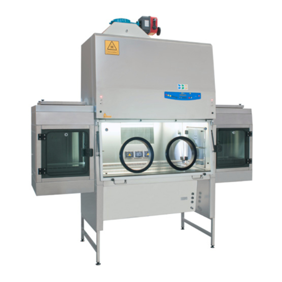
1 GENERAL Vertical laminar airflow isolators with positive pressure within the working area and physical separation between operator and product (gloves), the ASEPTIC isolators are principally designed to protect the material to be manipulated from contamination coming from environment. The filtered and sterile air passing through the main HEPA filter ensures optimum airflow laminarity on the work surface. -
Page 4: Installation
2 INSTALLATION 2.A INSTRUCTIONS AND CHECKS ON DELIVERY Considering the critical nature of the use of the ASEPTIC isolator and the need to keep it in optimum condition, installation is very important. ASEPTIC isolators are positioned on a pallet wrapped in an extensible film and contained in a package of multi-layer strapped cardboard or a wooden cage. -
Page 5: Celectric Connections And Installation Of The Work Surface
30 mA. The ASEPTIC can be supplied either with pneumatic or electric Air Tight Valve (ATV) to close and seal the isolator during sterilization phase or pressure decay test. - Page 6 D:GROUP Company Technical Features Table Description Unit ASEPTIC 2-4-2 Overall Dimensions (L x H x D) 2670x1500x880 Useful dimensions (L x H x D) 1200x700x600 Weigh Noise level dB (A) <51 Lighting level >1000 Main voltage 230V AC 2P+T...
-
Page 7: Operation Principles
D:GROUP Company 3 OPERATION PRINCIPLES The following are the working principles of the Aseptic isolators. The air (A) is sucked inside the isolator through an H14 HEPA filter by a dedicated fan from the laboratory. That process creates the positive pressure condition in the working area (B) to protect the products handled. -
Page 8: Operation
4 OPERATION 4.A SYSTEM AND PERFORMANCES CONTROLS The ASEPTIC isolator is provided with an automatic regulation system to keep constant the unidirectional down flow air speed and the positive pressure in the work chamber, even with the progressive clogging of the HEPA filters up to the maximum pressure supported by the motor-fans. -
Page 9: Csymbols Of The Control Panel
"0" position, the green light of the mains voltage is on (3); the LCD displays the model name "ASEPTIC". In this position the operator can activate only the fluorescent light (7), the optional U.V. lamp (14) and the power outlet (6) (with plug installed) and can see the data stored in the microprocessor by pressing the “STATUS”... - Page 10 a D:GROUP Company 8 UP/DOWN ARROWS Use the arrow keys to scroll the menu, to program changing parameters and to put in the password. Three passwords are programmed: 1) to start the isolator – 2) to enter the operator menu – 3) to enter the main menu to change the data input (allowed only to authorized technical staff –...
- Page 11 a D:GROUP Company Operating Time: Shows the operating time of the isolator from the moment when the main switch is positioned on "I" The LCD will display (for example) "WORK TIME=XXXXXh”. This value cannot be reset. 12 SPEED REDUCTION By pushing the corresponding red key the password (the same of start) is requested.
-
Page 12: Dmanagement And Programming
a D:GROUP Company 4.D MANAGEMENT AND PROGRAMMING Get access to operator menu when the cabinet is in stand-by pressing “ESC” [9] together with “UP arrow” [8] keys (password). The following diagram shows the organization of “OPERATOR MENU” By pressing “SET” [10] you can either go to the highlighted entry or confirm data entry while by pressing “ESC” [9] you go back to the beginning STAND-BY PASSWORD ESC+UP... - Page 13 a D:GROUP Company TIMER (countdown): use "UP/DOWN arrow" keys [8] to scroll the operator menu select “TIMER SET UP.” and press "SET" [10] key; the display will show: TIMER SET UP SET UP hh:mm input the desired time and press SET [10] to confirm press ESC to exit the operator menu the display will show alternatively the countdown and the standard information when the countdown finish an audible signal will advise the operator.
- Page 14 a D:GROUP Company UV PROGRAMMING: use "UP/DOWN arrow" keys [8] to scroll the operator menu select “UV PROGRAMMING” press "SET" [10]; and the display shows: UV LIGHTING LENGTH SET UP hh:mm input the desired time for the UV cycle and press SET [10] to confirm the display shows: .UV PROGRAMMING DATE &...
- Page 15 a D:GROUP Company LANGUAGE SELECTION use "UP/DOWN arrow" keys [8] to scroll the operator menu select “LANGUAGE” and press "SET" [10] key; the display will show: LANGUAGE English With the “up and down arrow” keys select the desired language (Italian, English, French, German, Spanish).
- Page 16 a D:GROUP Company DISPLAY OF HISTORICAL FILES use "UP/DOWN arrow" keys [8] to scroll the operator menu select “HISTORY VIEW” and press "SET" [10] key; the display will show: use "UP/DOWN arrow" keys to scroll through the list of the possible troubles happened . The list is in chronological order and contains up to 64 voices To conclude programming, press ESC”...
-
Page 17: Edisposal Of Wastes And Contaminated Materials
a D:GROUP Company 4.E DISPOSAL OF WASTES AND CONTAMINATED MATERIALS DISPOSAL OF ELECTRIC AND ELETTRONIC DEVICES (AEE) NFORMATION FOR UROPEAN NION USER This symbol on the device means that when it needs to be disposed, it must be handled separately from urban waste. At the moment of the disposal, contact the dealer, to receive information about the collect and disposal in accordance with the laws in force in the country. -
Page 18: Fergonomics
a D:GROUP Company MATERIALS, WHICH THE ISOLATOR IS MADE OF PARTS OF THE ISOLATOR MATERIALS External structure AISI 304 stainless steel Inside work chamber AISI 304 stainless steel Work surface AISI 316L stainless steel Motor-fans Galvanized steel Filters Frame: in aluminium alloy Filtration media: glass fibre Protection: aluminium grid/epoxy powder painted Gasket: polyurethane... -
Page 19: Limitations
Listed below are the most important guidelines to be followed and the main substances to be avoided to ensure the correct use of the ASEPTIC isolator: NEVER USE chlorine-based substances (e.g. sodium hypochlorite) as they are corrosive for the metal structure of the isolator, and in particular for stainless steel parts. -
Page 20: Operating Procedures
– That the isolator has been sterilized in case of change in the nature of work to be carried out 6.B SWITCHING ON the ASEPTIC isolator To start the isolator, proceed as indicated below: turn on the light by pushing the button [7] be sure that the frontal window is closed press the main key I/0 [1] (see chapter 4D.) and enter the password to switch on the ventilation. -
Page 21: D How Introduce Material
a D:GROUP Company 6.D How introduce material To introduce material in the isolator, it is necessary use the pass box mounted on the both sides of the isolator. The pass boxes have two timed doors electrical interlocked. To open the external doors you have to push the button on the control panel near the led that show the doors status: •... -
Page 22: Maintenance
7 MAINTENANCE 7.A INSTRUCTIONS FOR DAILY CLEANING OF ISOLATORS (by users) Clean the outside of the ASEPTIC isolator using a damp cloth soaked in soapy water or some other commonly available products for stainless steel surfaces. The procedure to follow is: –... -
Page 23: Cinstructions For The Sterilization With Clarus
a D:GROUP Company 7.C INSTRUCTIONS FOR THE STERILIZATION WITH CLARUS L-2 Procedure: 1. Connect the Clarus L-2 to the isolator like showed in the picture. Start signal for Clarus L-2 Inlet pipe Status signal of Clarus L-2 Outlet pipe 2. Close all the isolator doors 3. -
Page 24: Dinstructions For The Sterilization With Steris Vhp
a D:GROUP Company 7.D INSTRUCTIONS FOR THE STERILIZATION WITH STERIS VHP Procedure: 1. Connect the VHP to the isolator like showed in the picture. Inlet pipe 7 pins socket 4 pins socket Outlet pipe 2. Close all the isolator doors 3. -
Page 25: Emotors Earth Connection
a D:GROUP Company 7.E MOTORS EARTH CONNECTION If maintenance operations on internal parts are required while the cabinet is connected to the main supply please follow these steps: 1. disconnect the cabinet from the main supply 2. remove the panel to access the internal part of the cabinet 3. -
Page 26: Fhepa Filters (By Technical Assistance Personnel)
a D:GROUP Company 7.F HEPA FILTERS (by technical assistance personnel) ATTENTION: before replacing HEPA filters, the isolator must be decontaminated (see Para. 7C.) and a sterilization certificate must be issued to the technicians before starting the service operation. For the safety of the personnel and the environment, the use of relevant personal protection devices is recommended as well as the collection of the replaced HEPA filters in polyethylene bags. - Page 27 a D:GROUP Company LAF Filter (F1) Switch off the isolator and disconnect it from the mains Open the control board [1] turning the locks [2] with the proper exagonal key. 00254EN – Rev. 01 – 11/2012...
- Page 28 a D:GROUP Company Remove the internal panel [3] unscrewing the relevant fastening screws. Rotate the threaded bars [4] to release the HEPA filter [6]. (Rear view) Remove the HEPA filter wearing PPD and put it in a hermetically sealed polythene bag. Place the additional gasket (if it is not already present) on the filter shoulder frame opposite the shoulder gasket of filter (already present).
- Page 29 a D:GROUP Company Suction Filter (F2) Rotate the fastening threaded bars [7] to lift down the plenum group [8] and to release the HEPA filter. (Rear view) 10. Proceed as indicated in above 6, 7 points. 11. Lock the HEPA filter by rotating the fastening bolts [7]. 12.
-
Page 30: Greplacement Of Motor-Fans (By Technical Assistance Personnel)
a D:GROUP Company 7.G REPLACEMENT OF MOTOR-FANS (by technical assistance personnel) ATTENTION: before replacing the motor-fans, the isolator must be decontaminated and a sterilization certificate must be issued to the technicians before starting the operation (see par. 7D). For the safety of the personnel and the environment, the use of PVC gloves is recommended as well as the collection of the replaced materials in polyethylene bags. - Page 31 a D:GROUP Company Remove the main motor-fan [11] including the side stirrup [12]. Position the new motor-fan after having mounted again the flow sensor group [15] and the relevant stirrup. Fasten the motor-fan with the relevant screws and reconnect electrical connectors. Proceed as indicated in the sub section "Replacement of HEPA filters", points 12 and 13.
-
Page 32: Hreplacement Of Fluorescent Lamps (By Technical Assistance Personnel)
a D:GROUP Company Replacement of suction motor-fan. Proceed as indicated in sub-section "Replacement of HEPA filters", from 1 to 3 points and remove the suction HEPA filter. Remove the textile plenum Unscrew the screws that fasten the frontal panel of the exhaust plenum Remove the screws [20] of the suction fan [13] and the electrical connection. -
Page 33: Ispare Parts List
D:GROUP Company SPARE PARTS LIST CODE DESCRIPTION ASEPTIC V01 000019500 Pressure transmitter V20 000033020 AVE Plate IP-44 V20 000034030 Socket V20 000006040 36 W/84 fluorescent lamp V20 000006360 2x36W lamp holder V20 000006900 Power line filter V20 000006880 Magnetic sensor... -
Page 34: Monitoring System
a D:GROUP Company 8 MONITORING SYSTEM ALARM OR ERROR MESSAGE DESCRIPTION Min. LAF Alarm Airflow speed in the work chamber under minimum threshold value Min Pressure Alarm The pressure of the work chamber is raised under the minimum alarm value (60 Pa). It can be due to a hole in the gloves or to the opening of a door. -
Page 35: Troubleshooting - Probable Causes Of Malfunctions
a D:GROUP Company 9 TROUBLESHOOTING - Probable causes of malfunctions PROBLEM CAUSE REMEDY Isolator does not work – the electricity supply has – check the voltage input to been cut off at the mains the isolator – Electronic board out of order –... -
Page 36: Technical Specifications
a D:GROUP Company 10 TECHNICAL SPECIFICATIONS AISI 304 stainless steel. Perfectly air-tight structure with work External structure area under negative pressure. Work chamber Made from glazed AISI-304 stainless steel with radiussed angles AISI 316L stainless steel sheet (removable). Work surface AISI 304 stainless steel, located under the work surface Spillage tray H14 HEPA filters, according to EN 1822-1;... -
Page 37: Transport, Packing And Storage Instructions
a D:GROUP Company 11 TRANSPORT, PACKING and STORAGE INSTRUCTIONS ATTENTION: Disconnect the power and sterilize the unit before performing any of the following operations The following instructions are essential if the end user needs to transport, pack or store a isolator after a period of routine use (e.g. - Page 38 D:GROUP Company Cardboard outer package of the following dimension: Isolator model ASEPTIC 2-4-2 2800 2100 Steel straps and clips During transport take care to maintain the package in a vertical position (i.e. the pallet at the bottom) The isolator (with or without the package) must be kept in a place with the following environmental conditions: Min.
-
Page 39: Additional Information
12 ADDITIONAL INFORMATION 12.A GUARANTEE The guarantee for ASEPTIC vertical laminar air-flow isolators is 24 months from date of invoice. In addition to those cases specifically indicated in Chapter 5 relating to improper use of the isolator, the guarantee offered by Faster S.r.l., also excludes certain improper uses described in the instruction manual, of which the most important are listed again below: installation in a place which does not conform to the manufacturer’s recommendations... -
Page 40: Tests Performed According To En 14644-3 Standard
a D:GROUP Company 13 TESTS PERFORMED ACCORDING TO EN 14644-3 STANDARD 13.A MEASUREMENT OF LAMINAR AIRFLOW VELOCITY The LAF velocity is measured at 250 mm under the HEPA filter taking the reading in at least 8 points: In our tests the readings are taken in 12 points as above-diagrammed. Each one of the 12 readings lasts at least 1 minute. -
Page 41: Bmeasurement Of The Internal Pressure
a D:GROUP Company 13.B MEASUREMENT OF THE INTERNAL PRESSURE Check the internal pressure by connecting a calibrated manometer to the transparent pipe in the front control panel. Use a 3 ways “T” connector to allow the pressure transmitter and the calibrate manometer to be connected together. -
Page 42: Fcontrol Of Alarms
OTHER ALARMS With the help of FASTER’s technicians also the alarms for LAF and internal pressure below the minimum threshold or over the maximum threshold can be checked 00254EN – Rev. 01 – 11/2012... -
Page 43: Gdehs Test For Hepa Filters
a D:GROUP Company 13.G DEHS TEST FOR HEPA FILTERS OBJECT AND PRINCIPLE OF THE TEST: Check of the integrity of the HEPA filters through an analysis of the filtering system, able to find out possible small leaks and/or defects altering the efficiency of the filters and at the same time to test leaks around gaskets. -
Page 44: H Drawings And Diagrams
a D:GROUP Company 13.H Drawings AND DIAGRAMS LEGENDA Ref. DESCIPTION Main motor Suction HEPA Filter (F2) Suction Plenum LAF HEPA Filter (F1) Working Chamber Screws Front Window Screws. Front Window gas springs Control Panel locks Lamps Control Panel LAF Plenum SUCTION motor-fan LAF Fan Screws Fasten knob... -
Page 45: Idiagram For Maintenance Operations
a D:GROUP Company 13.I DIAGRAM FOR MAINTENANCE OPERATIONS 00254EN – Rev. 01 – 11/2012... - Page 46 a D:GROUP Company 00254EN – Rev. 01 – 11/2012...
-
Page 47: Jfrontal Diagram
a D:GROUP Company 13.J FRONTAL DIAGRAM 00254EN – Rev. 01 – 11/2012... -
Page 48: Kside Diagram
a D:GROUP Company 13.K SIDE DIAGRAM 00254EN – Rev. 01 – 11/2012... -
Page 49: Support Table
a D:GROUP Company 14 SUPPORT TABLE 00254EN – Rev. 01 – 11/2012... -
Page 50: Assemby Of The Isolator On The Supporting Stand
a D:GROUP Company 15 ASSEMBY OF THE ISOLATOR ON THE SUPPORTING STAND When the stand has been assembled the isolator can be installed following this procedure: Check the correct levelling of the stand and in case adjust the height of the feet [3] Check the tightening of all the screws and the firmness of the stand Lift the isolator with suitable equipment (for example a forklift) complying with the safety rules (the weight of the isolator is shown in the “table of technical features”... -
Page 51: Sensors List
a D:GROUP Company 16 SENSORS LIST SOFTWARE NAME PCB PLUG OF THE SENSOR DESCRIPTION not used not used not used Window closed Left footswitch Right footswitch not used Card NBHG Card NBHG 00254EN – Rev. 01 – 11/2012... -
Page 52: Wiring Diagram: Aseptic Equipped With Clarus
D:GROUP Company 17 WIRING DIAGRAM: ASEPTIC EQUIPPED WITH CLARUS L-2 00254EN – Rev. 01 – 11/2012... - Page 53 a D:GROUP Company 00254EN – Rev. 01 – 11/2012...
- Page 54 a D:GROUP Company 00254EN – Rev. 01 – 11/2012...
- Page 55 a D:GROUP Company 00254EN – Rev. 01 – 11/2012...
- Page 56 a D:GROUP Company 00254EN – Rev. 01 – 11/2012...
- Page 57 a D:GROUP Company 00254EN – Rev. 01 – 11/2012...
- Page 58 a D:GROUP Company 00254EN – Rev. 01 – 11/2012...
- Page 59 a D:GROUP Company 00254EN – Rev. 01 – 11/2012...
-
Page 60: Wiring Diagram: Aseptic Equipped With Steris Vhp
D:GROUP Company 18 WIRING DIAGRAM: ASEPTIC EQUIPPED WITH STERIS VHP 00254EN – Rev. 01 – 11/2012... - Page 61 a D:GROUP Company 00254EN – Rev. 01 – 11/2012...
- Page 62 a D:GROUP Company 00254EN – Rev. 01 – 11/2012...
- Page 63 a D:GROUP Company 00254EN – Rev. 01 – 11/2012...
- Page 64 a D:GROUP Company 00254EN – Rev. 01 – 11/2012...
- Page 65 a D:GROUP Company 00254EN – Rev. 01 – 11/2012...
- Page 66 a D:GROUP Company 00254EN – Rev. 01 – 11/2012...
- Page 67 a D:GROUP Company 00254EN – Rev. 01 – 11/2012...
-
Page 68: Declaration Of Conformity
D:GROUP Company 19 DECLARATION OF CONFORMITY The undersigned legal representative of the company Faster S.r.l. hereby declares that the follow products: Aseptic are in compliance with the following directives: 2006/42/EC Directive of the European Parliament and of the Council on machinery...
Need help?
Do you have a question about the ASEPTIC and is the answer not in the manual?
Questions and answers