Table of Contents
Advertisement
Quick Links
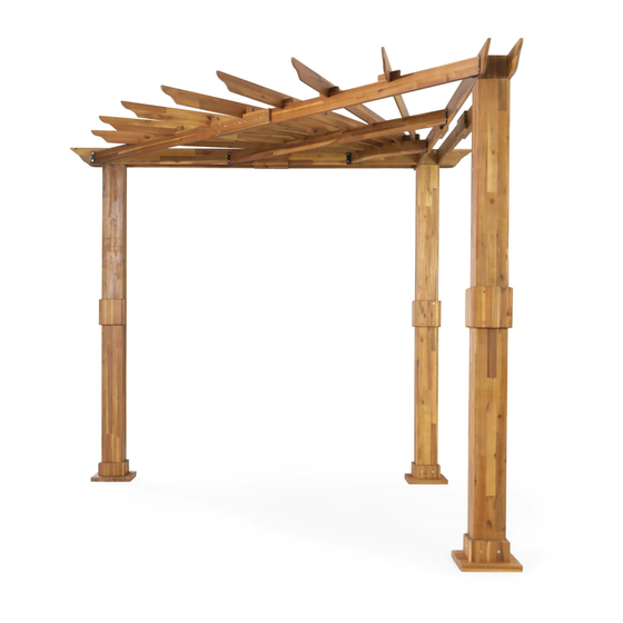
TRIANGULAR PERGOLA
Note 1: Post Mounting Hardware is NOT included in this kit.
Please confirm with your local hardware store to determine the correct hardware.
CAUTION: You must read this Assembly Instructions before you proceed.
Please look into the Corner Roof Support Joist package for all hardware.
CAUTION : IT IS RECOMMENDED THAT YOU :
1. ) DO NOT USE THE PERGOLA DURING INCLEMENT WEATHER.
2. ) ENSURE ALL CHILDREN ARE SUPERVISED, AT ALL TIMES, DURING USE OF PERGOLA.
3. ) UNATTENDED CHILDREN MUST NOT BE ALLOWED TO USE THIS PERGOLA.
4. ) DO NOT HANG ANY HEAVY OBJECT ONTO ANY PART OF THE PERGOLA.
5. ) USE STEP LADDERS ONLY TO ASSEMBLE THIS PERGOLA.
6. ) IN THE PROCESS OF ASSEMBLY, IF YOU SHOULD ACCIDENTALLY LOSE ANY HARDWARE,
DO NOT REPLACE WITH YOUR OWN HARDWARE.
7. ) IN THE PROCESS OF ASSEMBLY, IF YOU SHOULD ACCIDENTALLY DAMAGE THE WOOD,
DO NOT PROCEED WITH THE ASSEMBLY.
Assembly Instructions
Rear
Left
Front
Right
1 OF 46
Advertisement
Table of Contents

Related Manuals for Noble House Home Furnishings TRIANGULAR PERGOLA

Summary of Contents for Noble House Home Furnishings TRIANGULAR PERGOLA
- Page 1 Assembly Instructions TRIANGULAR PERGOLA Note 1: Post Mounting Hardware is NOT included in this kit. Please confirm with your local hardware store to determine the correct hardware. CAUTION: You must read this Assembly Instructions before you proceed. Please look into the Corner Roof Support Joist package for all hardware.
- Page 2 CAUTION : 1. ) It is highly recommended that you read and familiarise yourself with this Assembly Instructions before you proceed to assemble this Pergola. 2. ) This Pergola consists of MANY PARTS. These Parts - would require your actions to JOIN / CONNECT, to become Components.
-
Page 3: Maintenance Instructions
MAINTENANCE INSTRUCTIONS: 1. Check all nuts and bolts monthly twice after Installation and tighten as required. Note: Don’t overtight, which may lead to cracking of wood. 2. Inspect the wood parts monthly. Check for any sharp edges, lift in grains or splinters. If found, a light sanding is necessary, followed by the application of sealant. -
Page 4: Parts List
Parts List Description Picture Bundle I ) Parts of Pillars Upper Pillar Lower Pillar Pillar Joint - Key Pillar Mid Joinery - Anchor Panel ( with 4 (four) pcs of pre-attached wooden dowels ) Pillar Mid Joinery - Slide Panel with Grooves Note 2 : Upon completion of Bundle Part 1 assembly, you would have 3 ( three ) pcs of Pillar. - Page 5 Bundle II ) Parts of Foot Base & Foot Aprons Pillar Base : Foot Base Pillar Base : Foot Apron - Anchor Panel with 4 (four) pcs of pre-attached wooden dowels) Pillar Base : Foot Apron - Slide Panel Note 3 : Upon completion of Bundle Part II, you would have assembled all 3 ( three ) Pillars, complete with Foot Bases.
- Page 6 Bundle III ) Parts of Inner and Outer Joists to the Pillars. Outer Joist Outer Slotted - Joist - Right Outer Slotted - Joist - Left Inner Joist Inner Slotted - Joist - Right Inner Slotted - Joist - Left Joinery - Short Joist Note 4 : Each JOISTS would need 2 pcs of Joinery - Short Joists ( C7 ) to complete the Inner and Outer Joists.
- Page 7 Right Outer Joists Right Inner Joists Left Outer Joists Left Inner Joist Bundle IV ) Parts of Front Roof Support Joist Front Roof Support Joist - Left Front Roof Support Joist - Right Front Joist Joint - Long Front Joist Joint - Key Metal Cleat 7 OF 46...
- Page 8 Connect Joists Hole Note 5 : Upon completion of the assembly of the Front- Left & Right - Roof Support Joist 1 and 2 Joist, this completed Joist now becomes the FRONT ROOF SUPPORT JOIST. Please ensure all Bolts and Screws are FULLY tighten after these are assembled. The Metal Cleat is placed and sandwiched between the Wood Joists.
- Page 9 Component V. ) Middle Roof Support Joist Middle Roof Support Joist Component VI. ) Corner Roof Support Joist Corner Roof Support Joist Component VII. ) Roof Slats Roof Slat Note 6 : The above Components forms the Roof Support Joists and Roof Slats : Component E - is the Middle - Roof Support Joist Component F - is the Corner - Roof Support Joist Component G - is the Roof Slats...
-
Page 10: Hardware List
Hardware List Description Picture Screw (M4x40mm) Bolt (M6x15mm) Bolt (M6x45mm) Bolt (M6x60mm) Screw (M7x50mm) Screw (M7x70mm) Sleeve Nuts (M6x18mm) Flat Washer (Ø6.5/16x1mm) Allen Wrench (M4 x 80mm) Screw (M4x15mm) 12 (Not Garden Stake provided) (M10 x 300 mm) Screw Driver provided Note 7: Quantity in the Hardware List included extra hardware for each type of hardware. -
Page 11: Assembly Preparation
Assembly Preparation Parts of Foot Base & Foot Aprons Parts of PILLARs. Parts of Inner and Outer Joists, connected to become the RIGHT and LEFT : Inner and Outer Joists. Parts of FRONT - Roof Support Joist 11 OF 46... -
Page 12: Hardware Pack
Component - MIDDLE - Roof Component - CORNER - Roof Support Joist Support Joist Component - Roof Slats HARDWARE PACK x 17 x 51 x 15 x 15 x 29 x 11 x 12 (Not x 59 provided) x 26 12 OF 46... -
Page 13: Assembly Steps
Assembly Steps OVERVIEW 1. Outer Slotted - Joist - Left (C3) Front Joist Joint - Key (D4) Outer Slotted - Joist - Right (C2) Inner Slotted - Joist - Right (C5) Inner Slotted - Joist - Left (C6) Outer Joist (C1) Joinery - Short Joist (C7) Inner Joist (C4) Outer Joist (C1) - Page 14 OVERVIEW 2. RIGHT - Outer Joist CORNER - Roof Support Joist (F) MIDDLE - Roof Support Joist (E) RIGHT - Inner Joist LEFT - Outer Joist LEFT - Inner Joist FRONT -Roof ROOF Slats ( G) Support Joist Pillar Front In image OVERVIEW 2 above, it is intended to give you an overview on all the COMPONENTS that are to be assembled to become the Pergola.
-
Page 15: Upper End
Step 1 As the Pergola is tall, wide and heavy, we recommend : 1. ) That you identify and mark your ideal location where to place / position this Pergola. By so doing, would mean minimal moving about of the partial and or fully assembled Components and Pergola. - Page 16 Step 3 Upper Lower UPPER END GROUND END There are 2 (two) pcs of Pillar MID JOINERY - Anchor Panel ( A4 ) slats. There is a distinct Instep at the Upper portion of this Anchor Panel. These Mid Joinery panels has Pre-attached Wooden Dowels. Ensure there are 4 ( four ) pieces of pre-attached Wooden Dowels on each Anchor Panel before assembly.
- Page 17 Step 4 Final assembly to the Pillars : Slide Panel ( A5 ) has a distinct open groove at the sides of the panel, as shown in the picture. At this step, One Partner shall hold firmly to the previously attached 2 ( two ) pieces of MID JOINERY - Anchor Panel ( A4 ) from Step 3.
- Page 18 Step 5 Upper GROUND END UPPER END In Step 5, this assembly step is to affix the FOOT APRON - Anchor Panel (B2) to the Pillar. Each FOOT APRON panel has 2 (two ) Pre-attached Wooden Dowels. Each FOOT APRON panel has a distinct Upper and Lower feature. For ease of assembly, place a box or an object to prop up the Pillar, at the foot base end, as shown above.
- Page 19 Step 6 Upper Here, in Step 6, it would require 2 people to assemble the Foot Apron. At this step, One Partner shall hold firmly to the previously attached 2 ( two ) pieces of FOOT APRON - Anchor Panel (B2) from Step 5, above. The other partner shall place and position the FOOT APRON - Slide Panel (B3) between the 2 ( two ) pieces of FOOT APRON - ANCHOR PANEL ( B2 ).
-
Page 20: Safety Reminder
Step 7 Upper Here, in Step 7, is a single-man job, in the assembly of the Foot Base to the Pillar. Keeping the Pillar in the same propped position from above, proceed to attach the Foot Base ( B1 ). Attach the FOOT BASE ( B1 ) to the Pillar with Screws (⑥). - Page 21 Step 9 Here in Step 9, will require your Partner and you to connect 02 ( two ) pieces of Joists together to form the Right Outer Joists. The OUTER JOIST (C1) is to be connected to the OUTER SLOTTED - Joist - Right (C2). Sandwich the Outer Joist and Outer Slotted with 2 ( two ) pieces of Joinery - Short Joist C7 ), as shown above.
- Page 22 Step 10 Here in Step 10, will require your Partner and you to connect 02 ( two ) pieces of Joists together to form the Right Inner Joists The INNER JOIST (C4) is to be connected to the INNER SLOTTED - Joist - Right (C5). Sandwich the Inner Joists and Inner Slotted with 2 ( two ) pieces of Joinery - Short Joist (C7 ), as shown above.
- Page 23 Step 11 Here in Step 11, will require your Partner and you to connect 02 ( two ) pieces of Joists together to form the Left Outer Joists The OUTER JOIST (C1) is to be connected to the OUTER SLOTTED - Joist - Left (C3). Sandwich the Outer Joists and Outer Slotted with 2 ( two ) pieces of Joinery - Short Joist C7 ), as shown above.
- Page 24 Step 12 Here in Step 12, will require your Partner and you to connect 02 ( two ) pieces of Joists together to form the Left Inner Joist. The INNER JOIST (C4) is to be connected to the INNER SLOTTED - Joist - Left (C6). Sandwich the Inner Joist and Inner Slotted with 2 ( two ) pieces of Joinery - Short Joist C7 ), as shown above.
- Page 25 Note 10 : Steps 13 and 14, herebelow, are steps to assemble to FRONT - Roof Support Joist. It is a 2 ( two ) step process as it has a double secure locking system. Step 13 involves the locking a METAL CLEAT ( D5 ) into place. Step 14 involves the locking into position of WOODEN KEY Joist.
- Page 26 Step 14 Step 14, takes you to assemble the second secure system for the FRONT - Roof Support Joists. With assistance from your adult partner, turn the FRONT - Roof Support Joists 90 degrees then affix the FRONT - Roof Support Joist by "joining and connecting" with 1 (one ) piece of Front Joist Joint - Key (D4) and 1 ( one ) piece of Front Joist Joint - Long (D3).
- Page 27 Step 15 Rear Right Left Front By now, if your ideal location to place / position the Pergola has not been marked, it is recommended that this is done so, now. The Pergola is tall, wide and heavy. Therefore, to avoid any injury and or damage to the Pergola, it is best to assemble the Pergola closest to your ideal location.
- Page 28 Step 16 Here, in Step 16, it is recommended to have 3 (three ) adults at hand, to facilitate the assembly and putting into position the partially assembled Pergola panel. With assistance from your adult partners, position 2 ( two ) pcs of Pillars approximately 7 (seven ) feet apart, closest to your marked ideal location.
- Page 29 Step 17 17.3 ) Gently and slowly 17.2 ) Stand the 17.1 ) Lift the partially lower the partially assembled partially assembed asembled Pergola (by panel to the ground to allow for Pergola at 90degrees to the Pillar area), that is theother Joists to be attached the ground.
- Page 30 Step 18 Upon placing the partially assembled RIGHT Panel of the Pergola onto the ground, proceed to fix the RIGHT INNER Joists. There are a total of 4 ( four ) points. Affix using Screws (⑤) and Allen Wrench (⑨). There are a total of 4 Screws to be affixed.
- Page 31 Step 19 With assistance from your adult partners, slowly and carefully, stand upright the, RIGHT - Pergola Panel. This Pillar Panel would require 4 (four) pcs of Garden Stakes ( NOT provided) per Pillar that needs to be staked into the ground to keep the Pillar affixed into the ground.
- Page 32 Step 20 In Step 20 here, it is recommended that a 4(four) man team is effective, to get the Pergola assembled. Additionally, 2 Step Ladders are needed,2 ( two ) adult partners would be required to be on the Step Ladders. The 3rd ( third ) partner is recommended to assist to hold / keep the Pillar stable.
- Page 33 Step 21 REAR Here in Step 21, this step is a 3-man team assembly. There will be 2 ( two ) partners on the 2 ( two ) Step Ladders, positioned at / near the REAR and LEFT Pillars . The 3rd partner, on the ground, will hand the relevant component to be assembled..
- Page 34 Step 22 Here in Step 22, the 3rd ( third ) partner will hand to the adult partners, the LEFT - OUTER JOIST, due the 2 ( two ) partners are on the 2 ( two ) Step Ladders. Affix this Outer Joists to the PIllars by using Screws (⑤) and Allen Wrench (⑨). There are a total of 4 ( four ) Screws to be affixed.
- Page 35 REMINDER STEP Step 23 - Throughout all of the above assembly steps, you have been guided to FULLY SECURE and TIGHTEN all Bolts and Screws. At this juncture, DO NOT PROCEED to the next step, instead, proceed to INSPECT AND ENSURE THAT ALL BOLTS, SLEEVE NUTS AND SCREWS ARE FULLY SECURED AND TIGHTENED.
- Page 36 With assistance from your adult partners, re-position the Step Ladders, as indicated above, for better access and for connection of the CORNER - ROOF SUPPORT JOIST ( F ), to both the RIGHT and LEFT Inner Joists. To avoid any deformation to the angle point of assembly, both partners MUST connect this CORNER - Roof Support Joist, TOGETHER AND AT THE SAME TIME.
- Page 37 Step 25 37 OF 46...
-
Page 38: At The Same Time
Here in Step 25, the role of each partner is similar to Step 24. Proceed to re-position the Step Ladders, midway of both the LEFT and RIGHT Outer and Inner Joists area. On the Step Ladders, attach the Middle Roof Support Joist (E) into the housing in the middle of both the LEFT and RIGHT - Inner Joists. - Page 39 Step 26 39 OF 46...
- Page 40 Here in Step 26, proceed to the fixture of the FRONT - Roof Support Joist With assistance from your adult partners, re-position the Step Ladder to the Front area of both the RIGHT and LEFT Pillars. Attach and connect the FRONT - Roof Support Joist from Step 14, to both the LEFT and RIGHT - Inner Joists.
- Page 41 Step 27 41 OF 46...
- Page 42 Here, you are nearly at the final assembly step of this Triangular Pergola. These 3 ( three ) pieces of Roof Slats (G) on the right are the last components to be placed and affixed onto all 3 ( three ) Roof Support Joists.
- Page 43 Step 28 Here in Step 28 is a visual guide to show you the MIDDLE ROOF SLAT, that has a slight different fixture position, compared to the other six roof slats You will find an Extended Wood Block at the MIDDLE JOIST area, with a predrilled pilot hole.
- Page 44 44 OF 46...
- Page 45 Descend form the Step Ladders... Then, STAKE IN ALL the GARDEN STAKES ( not provided ) FULLY AND COMPLETELY into the garden grounds. The above completes the assembly for Your Triangular Pergola, and is ready for use. 45 OF 46...
-
Page 46: Care And Maintenance
Care & Maintenance ● Do not put hot items directly on furniture surface. ● Do not clean furniture with harsh cleansers or polish. ● Children should not climb or jump on the Pergola. ● Do not write on furniture without a padded barrier to protect the surface.
Need help?
Do you have a question about the TRIANGULAR PERGOLA and is the answer not in the manual?
Questions and answers