
Related Manuals for HNC Electric HV100 Series


Summary of Contents for HNC Electric HV100 Series
- Page 1 HV100 Series High Performance Current Vector Inverter HV100 Series Frequency Inverter User Manual HNC Electric Limited...
-
Page 2: Table Of Contents
HV100 Series High Performance Current Vector Inverter Contents Contents..................................1 Chapter I Safety Information............................ 3 1.1 Marks and definitions of safety information..................3 1.2 Use range..............................3 1.3 Installation Environment........................3 1.4 Installation safety matters........................4 1.5 Use safety matters............................ 5 Chapter II Standard Specifications of Products....................6 2.1 Technical specifications.........................6... - Page 3 HV100 Series High Performance Current Vector Inverter 8.3 EMC guidance............................126 8.3.1 Influence of harmonics:......................126 8.3.2 Electromagnetic interference and installation precautions:..........126 8.3.3 Treatment method of interference of peripheral electromagnetic equipment....126 8.3.4 Measures to deal with interference caused by inverter to peripheral equipment:..126 8.3.5 Leakage current and treatment:....................127...
-
Page 4: Chapter I Safety Information
HV100 Series High Performance Current Vector Inverter Chapter I Safety Information 1.1 Marks and definitions of safety information The safety clauses described in this User‘s manual are very important, which can ensure you to use the inverter safely, and prevent yourself or the people around you from being hurt and the property in the working area from being damaged. -
Page 5: Installation Safety Matters
HV100 Series High Performance Current Vector Inverter ● The environmental humidity is required to be lower than 90%, and there is no condensation of water droplets. ● it is installed in a place with vibration less than 0.5G to prevent falling damage. The inverter is not allowed to suffer sudden impact. -
Page 6: Use Safety Matters
HV100 Series High Performance Current Vector Inverter Attention ● The electromagnetic contactor should not be installed on the output side of the inverter, because the contactor will turn on and off when the motor is running, which will produce operating overvoltage and cause damage to the inverter. -
Page 7: Chapter Ii Standard Specifications Of Products
HV100 Series High Performance Current Vector Inverter Chapter II Standard Specifications of Products 2.1 Technical specifications Rating Voltage , Three-phase (G3/G4 series) 380V-480V, 50/60HZ Frequency Single&Three-phase (G1/G2 series) 220 V: 50/60 Hz Input Three-phase (G3 series) : AC 380~440 (-15%~+10%) - Page 8 HV100 Series High Performance Current Vector Inverter 2 analog signals are output, and the output range can be flexibly set between 0 ~ 20mA or 0 ~ 10V, which can Analog output realize the output of physical quantities such as set...
- Page 9 HV100 Series High Performance Current Vector Inverter 2.2 Inverter model description 2.2.1 Product naming Brake unit Empty Built-in nverter series Code Voltage class Code Adaptation motor power Type Code General Fan/Pump type Figure 2-1 Naming Rules 2.2.2 Nameplate marking Rated nameplate...
-
Page 10: Inverter Model Description
HV100 Series High Performance Current Vector Inverter 2.3 Size of inverter and keyboard Figure 2-3 Dimensions of Inverter 0.75KW~30KW Installation hole (mm) (mm) (mm) (mm) (mm) (mm) Model No. Mounting Exterior dimensions dimension Single phase 0.4KW-2.2KW AC220V 0.4KW-2.2KW Three phase 4KW-5.5KW... - Page 11 HV100 Series High Performance Current Vector Inverter Keyboard dimensions:...
-
Page 12: Rated Current Output Meter
HV100 Series High Performance Current Vector Inverter 2.4 Rated current output table Single - phase Three-phase Voltage 220V 220V 380~480V Power(KW) Current (A) Current (A) Current (A) 0.75 18.5 2.5 Selection of Braking Resistance Table Braking Brake resistance specification Inverter power... - Page 13 HV100 Series High Performance Current Vector Inverter Notes: 1. Please select the resistance value specified by our company. 2. Our company will not be liable for any damage to the inverter or other equipment caused by the use of brake resistors other than those provided by our company.
-
Page 14: Chapter Iii Storage And Installation
HV100 Series High Performance Current Vector Inverter Chapter III Storage and Installation 3.1 storage This product must be placed in a packing box before installation. If it is not used temporarily, please pay attention to the following items when storing: ●... -
Page 15: Chapter Iv Wiring
HV100 Series High Performance Current Vector Inverter Chapter IV Wiring 4.1 Main circuit wiring diagram Power supply: Please pay attention to whether the voltage levels are consistent, so as not to damage the inverter. Fuseless switch: please refer to the corresponding table. -
Page 16: The Terminal For Controlling Loop
HV100 Series High Performance Current Vector Inverter 4.2.2 The terminal for controlling loop Function description of control circuit terminal Classifica Terminal Description of functions Specification tion label Short circuit between DI(DI1, DI2, DI3, DI4, DI5, DI6, HDI) ~ COM is valid, and its functions are set by parameters 07.00 ~ 07.06 respectively... -
Page 17: Jumper Settings Of Main Control Board
HV100 Series High Performance Current Vector Inverter +24V is the circuit common power supply of +24V Maximum output current 200mA digital signal input terminal +10V is the circuit common power supply of +10V Maximum output current 20mA analog input and output terminals The factory default is OP connected to +24V. -
Page 18: Main Circuit Wiring
HV100 Series High Performance Current Vector Inverter Braking resistance Circuit breaker Default Open collector output 1 Open collector output 2 (Reserved) Relay R1 For the selection of voltage and Relay R2 Potentiometer current signals, refer to jumpers on the previous page... -
Page 19: Matters Needing Attention For Wiring
HV100 Series High Performance Current Vector Inverter ● When the wiring between the inverter and the motor exceeds 50m (220V series) and 100m (380V class), high dv/dt will be generated in the coil of the motor, which will damage the interlayer insulation of the motor. Please use the AC motor dedicated to the inverter or install a reactor on the inverter side. -
Page 20: Matters Needing Attention In Motor Use
HV100 Series High Performance Current Vector Inverter (5) Special options Terminals PB(+) and P1(+) are terminals for connecting with special optional items. Do not connect machines other than special options. (6) Precautions related to reciprocating load When the inverter is used for reciprocating loads (cranes, elevators, punching machines, washing machines, etc.), if 150% or more of the current flows repeatedly, the service life of IGBT inside the inverter will be shortened due to thermal fatigue. -
Page 21: Chapter V Operation And Display
HV100 Series High Performance Current Vector Inverter Chapter V Operation and display 5.1 keypad description 5.1.1 Diagram of keypad 5.1.2 Key Description Key symbol Name Functional Description Programming key Menu entry or exit, parameter modification ENTER Confirm key Enter the menu and confirm the parameter setting ▲... -
Page 22: Operation Process
HV100 Series High Performance Current Vector Inverter 5.2 Operation process 5.21 Parameter setting The three-level menus are: 1. Function code group number (level 1 menu); 2. Function code label (secondary menu); 3. Set value of function code (Level 3 menu). -
Page 23: Chapter Vi Functions And Parameter Table
HV100 Series High Performance Current Vector Inverter Chapter VI Functions and Parameter Table Symbols in the menu are described as follows ×: Parameters that can be modified in any state ○: Non modifiable parameters in operation state ◆: Actual test parameter, cannot be modified ◇: The manufacturer' parameters can only be modified by the manufacturer, but not by the user. - Page 24 HV100 Series High Performance Current Vector Inverter 0: Digital setting 1(press keyboard key▲/▼, encoder +00.10) 1: Digital setting 2(UP/DOWN terminals +00.10) 2: Digital setting 3(Communication setting) 3: AI1 analog setting(0~10V/20mA) Selection of main 4: AI2 analog setting(0~10V) 00.04 frequency source 0~11...
- Page 25 HV100 Series High Performance Current Vector Inverter Frequency source This set value is the initial value of frequency digital 0.00Hz~ 00.10 digital given 2 50.00 ○ given 2 【00.13】 setting Setting of auxiliary frequency source K is the weight coefficient of auxiliary frequency 00.11...
- Page 26 HV100 Series High Performance Current Vector Inverter 0~65535 Note1: 0~9: No password protection Note2: Password is set successfully, waiting for 3 00.20 User password 0~65535 ○ minutes to take effect Note3: Write protection is not valid for this parameter and cannot be initialized...
- Page 27 HV100 Series High Performance Current Vector Inverter Time for DC 01.12 braking during 0.0~100.0s ○ stop Acceleration Type 01.13 Set Acceleration Time 2 ○ Time 2 setting 0.1~3600.0S Deceleration Type 01.14 Set Deceleration Time 2 ○ Time 2 0.4~4.0KW setting 7.5S...
- Page 28 HV100 Series High Performance Current Vector Inverter Stop delay time when frequency is lower than lower Set stop delay time when frequency is lower than 01.32 0.0~3600.0s 10.0 ○ limit frequency lower limit frequency (Simple dormancy) (Simple dormancy) 0.0~ Zero frequency This parameter is the percentage of the rated current 01.33...
- Page 29 HV100 Series High Performance Current Vector Inverter 02.11 Reserved — — ◆ ~02.15 0: No action Motor tuning 02.16 1: Static tuning 0~2 × selection 2: No-load complete tuning Pre-excitation holding time of Model 02.17 Note: This parameter is invalid for VF control.
- Page 30 HV100 Series High Performance Current Vector Inverter -200.0%~ Keyboard digital The set value is a percentage of the rated current of 04.13 0.0% ○ setting torque the motor 200.0% Speed limit channel selection 0: keypad digital given1 04.14 1 for torque control 1: AI1 0~2...
- Page 31 HV100 Series High Performance Current Vector Inverter Static friction 04.27 coefficient 0.00~600.00s 0.00 × maintenance time 005Group-V/F Control Parameter Function Name Content Setting range Factory Alteration code 0: Linear curve 1: Torque reduction curve 1(1.3 power) 2: Torque reduction curve 1(1.5 power) 05.00...
- Page 32 HV100 Series High Performance Current Vector Inverter 0: VF semi-separated mode, voltage open loop output 1: VF semi-separated mode, voltage closed loop output 2: VF fully separated mode, voltage open-loop output 3: VF fully separated mode, voltage closed-loop output Selection of Note 1: When VF separate control is selected, please 05.12...
- Page 33 HV100 Series High Performance Current Vector Inverter This voltage represents the output voltage of the Limiting voltage of inverter, and setting this parameter reasonably can 0.0~100.0%* 05.24 voltage feedback 80.0% ○ prevent equipment damage caused by voltage rated volt disconnection overshoot at the time of disconnection.
- Page 34 HV100 Series High Performance Current Vector Inverter Analog input When the analog input signal fluctuates frequently near a 0.00V~ 06.12 anti-shake given value, the frequency fluctuation caused by this 0.00 ○ 10.00V deviation limit fluctuation can be suppressed by setting 06.12.
- Page 35 HV100 Series High Performance Current Vector Inverter AO1 output upper 0.00~ 06.27 Set AO1 output upper limit 10.00 ○ limit 10.00V AO2 output lower limit corresponds Set AO2 output lower limit corresponds to physical -200.0%~ 06.28 0.0% ○ to physical quantity 200.0%...
- Page 36 HV100 Series High Performance Current Vector Inverter AI1 curve inflection point 2 -200.0%~ 06.42 input 60.0% ○ 200.0% corresponding setting AI1 curve 【06.41】~ 06.43 10.00 ○ maximum input 10.00 AI1 curve maximum input -200.0%~ 06.44 100.0% ○ corresponding 200.0% setting 0.00~...
- Page 37 HV100 Series High Performance Current Vector Inverter 8: External equipment fault normally open (NO) input 9: External equipment fault normally close (NC) input 10: Emergency stop function (brake at the fastest speed) 11: External stop control 12: Frequency increase control(UP)
- Page 38 HV100 Series High Performance Current Vector Inverter filtering Selection of 0: Terminal running command is invalid when power on terminal function 07.09 0~1 ○ detection when 1: Terminal running command is valid when power on power on 0 means positive logic, that is, the Xi terminal is...
- Page 39 HV100 Series High Performance Current Vector Inverter communication failure, keypad communication failure, EEFROM reading and writing failure, encoder disconnection alarm, etc.) 23: AI1>AI2 24: length reach output 25: Timing time arrives 26: Dynamic braking action Programmable 07.20 0~62 × 27: DC braking action...
- Page 40 HV100 Series High Performance Current Vector Inverter 0.00Hz~ 07.25 FDT1 level set 50.00 ○ 【00.13】 0.0~ 07.26 FDT1 lag value 100.0%* 2.0% ○ 【07.25】 FDT2 detection 0: Frequency set value 07.27 0~1 ○ mode 1: Frequency test value 0.00Hz~ 07.28 FDT2 level set 25.00...
- Page 41 HV100 Series High Performance Current Vector Inverter 008group-PID Control Parameter Function Setting Name Content Factory Alteration code range 0: Automatic PID operation 08.00 0~1 1: Manually operation through the defined multi-function × mode terminal 0: Digital given 1: AI1 2: AI2 PID setting 08.01...
- Page 42 HV100 Series High Performance Current Vector Inverter Sampling period is the sampling period of feedback, and the regulator operates once in each sampling period. The larger the sampling period, the slower the response, 0.01~ 08.08 0.10 Sampling period T ○...
- Page 43 HV100 Series High Performance Current Vector Inverter 0.0~ 08.18 Wake delay time ○ 3600.0s 08.12=2 schematic diagram (sleep mode 2) Proportional gain 0.01~ 08.19 1.00 ○ The speed of PID adjustment is set by two parameters: 100.00 proportional gain and integration time. For fast...
- Page 44 HV100 Series High Performance Current Vector Inverter -Upper limit frequency~ Multistage speed 09.09 Set Multistage speed frequency 3 20.00 ○ frequency 3 Upper limit frequency -Upper limit Multistage speed frequency~ 09.10 Set Multistage speed frequency 4 25.00 ○ frequency 4...
- Page 45 HV100 Series High Performance Current Vector Inverter 4th speed Set the 4th stage speed acceleration and deceleration acceleration and 0~3 09.30 ○ time deceleration time 4th speed running 0.0~6553.5s time 09.31 Set the 4th stage speed running time ○ (min)
- Page 46 HV100 Series High Performance Current Vector Inverter Swing frequency 0: Invalid 09.55 0~1 × control 1: Effective 0: Automatic Swing frequency 09.56 1: Manually operation through the defined multi-function 0~1 × operation mode terminal Swing amplitude 0: Fixed swing 09.57 0~1...
- Page 47 HV100 Series High Performance Current Vector Inverter Actual length = calculated length × Length magnification Measure the 0.10~ 09.72 circumference of 10.00 ○ ÷ Length correction factor. 100.00CM shaft When the actual length (09.69) ≥ the set length (09.68), the inverter will automatically issue a shutdown Number of pulses instruction to stop.
- Page 48 HV100 Series High Performance Current Vector Inverter means 0.01Hz /s, and so on, and 5000 means 50.00/s. The load drop detection time (10.10) defines that the Drop load 10.10 0.1S~60.0S ○ detection time output current of the frequency converter is less than the load drop detection level (10.11) for more than a certain...
- Page 49 HV100 Series High Performance Current Vector Inverter Selection of 0: Protection action and free stop RS485 10.24 0~2 1: Alarm and maintain the status to continue operation × communication abnormal action 2: Alarm and stop according to the stop mode...
- Page 50 HV100 Series High Performance Current Vector Inverter 0: No check(N,8,1)for RTU 1: Parity check(E,8,1)for RTU 2: Odd parity check(0,8,1)for RTU 11.03 Date format 0~5 × 3: No check(N,8,2)for RTU 4: Parity check(E,8,2)for RTU 5: Odd parity check(0,8,2)for RTU Local machine...
- Page 51 HV100 Series High Performance Current Vector Inverter LED single digit: Display and selection of communication bus voltage 0: Normal display 1: Magnify 10 times 2: Magnify 100 times 3: Shrink 10 times 4: Shrink 100 times LED10 digit: Communication current display selection...
- Page 52 HV100 Series High Performance Current Vector Inverter Automatic fault reset times The frequency of automatic fault reset is set by 12.06. When the number of fault resets is set to 0, there is no 12.06 automatic reset function, and it can only be reset 0~100...
- Page 53 HV100 Series High Performance Current Vector Inverter Speed tracking When speed tracking restarts, select the speed of speed speed tracking. The smaller the parameter, the faster the tracking speed. But too fast may lead to unreliable 12.17 1~125 tracking. ×...
- Page 54 HV100 Series High Performance Current Vector Inverter Special function LED single digit: AO2 and DO selection 0: AO2 Effective 1: DO Effective LED10 digit: IPM Fault setting 0: Shield the fault 12.25 000~110 × 1: the fault is Effective LED100 digit: input phase failure rest selection...
- Page 55 HV100 Series High Performance Current Vector Inverter STOP+RUN 0: Forbid emergency stop 14.02 0~1 ○ 1: Free stop function Closed loop This function code is used to correct the display error display coefficient between the actual physical quantity (pressure, flow, 0.01...
- Page 56 HV100 Series High Performance Current Vector Inverter 0: No operation 1: Upload parameters to the keypad 2: Download all function code parameters to the inverter 3: Download all function code parameters except motor parameters to the inverter Note 1: When selecting parameter download, the 14.14...
- Page 57 HV100 Series High Performance Current Vector Inverter Function Setting Name Content Factory Alteration range code Lack water 16.00 0~250s ○ detect time 0 ~ MPPT MPPT low point High If the bus voltage (d-12) is higher than the set value of 16.01...
- Page 58 HV100 Series High Performance Current Vector Inverter BIT11: Torque limiting BIT12: Speed limiting BIT13: Speed control BIT14: Torque control BIT15: Reserved Multi segment speed mode,current 0~15 d-24 ◆ segment number 0~50000Hz Pulse frequency output(Hz) d-25 ◆ Reserved — d-26 ◆...
- Page 59 HV100 Series High Performance Current Vector Inverter Chapter VII Description of Function Parameters 000 group-basic operating parameters LCD language (only valid for LCD keypad) 00.00 0~2 0: Chinese 1: English 2:Reservation Functional macro definition 00.01 0~20 0:General model 1: Single pump constant pressure water supply mode...
- Page 60 HV100 Series High Performance Current Vector Inverter Operation control is implemented by multi-function terminals defined as FWD, REV, JOG forward rotation, JOG reverse rotation and other functions. 2: Communication operation command channel Operation control is implemented by the upper controller through communication.
- Page 61 HV100 Series High Performance Current Vector Inverter Selection of auxiliary frequency source B 00.05 0 ~ 11 (same as main frequency channel selection) 0: digital setting 1 (press keyboard key , encoder+00.10) 1: digital setting 2(UP/DOWN terminal adjustment) 2: digital setting 3 (communication setting)
- Page 62 HV100 Series High Performance Current Vector Inverter When the inverter is powered on, the panel frequency increment is initialized to the value saved in EEPROM during the last power failure. 1:not store When the inverter is powered on, the panel frequency increment is initialized to 0.
- Page 63 HV100 Series High Performance Current Vector Inverter The maximum output frequency is the highest frequency allowed by the inverter, which is the benchmark for setting acceleration and deceleration time, as shown in the figure fmax below. The basic operating frequency is the minimum frequency corresponding to the highest voltage output by the inverter, which is generally the rated frequency of the motor, as shown in the figure below.
- Page 64 HV100 Series High Performance Current Vector Inverter Output frequency Max output frequency Time Figure 00-2 Schematic diagram of acceleration time and deceleration time Running direction setting 00.18 0~2 0: Forward direction When this mode is selected, the actual output phase sequence of the inverter is consistent with the default phase sequence of the system.
- Page 65 HV100 Series High Performance Current Vector Inverter Group 01-start-stop control parameters Starting mode 01.00 0~2 0: Starting frequency starting Start according to the set starting frequency (01.01 ) and starting frequency holding time (01.02 ). 1: DC braking+starting frequency starting First DC brake (refer to 01.03 and 01.04), and then start according to mode 0.
- Page 66 HV100 Series High Performance Current Vector Inverter Output Frequency Time Current output (effective values) DC braking capacity DC braking time Time Run Command Figure 01-2 Diagram of starting DC brake Acceleration / deceleration mode 01.05 0~1 0: Straight line acceleration / deceleration The relationship between output frequency and time increases or decreases according to a constant slope, as shown in the following figure.
- Page 67 HV100 Series High Performance Current Vector Inverter After receiving the shutdown command, the inverter gradually reduces the output frequency according to the deceleration time, and stops after the frequency drops to zero. If the shutdown DC braking function is valid, the DC braking process will be executed after reaching the shutdown DC braking start frequency (according to 01.09 setting, a shutdown...
- Page 68 HV100 Series High Performance Current Vector Inverter Tips: Acceleration and deceleration time 1 is defined in 00.16 and 00.17. Selection of acceleration and deceleration time unit 01.19 0~2 0: Second 1: Minute 2:0.1 second This function code defines the dimension of acceleration and deceleration time.
- Page 69 HV100 Series High Performance Current Vector Inverter The above function codes are functions set to make the output frequency of inverter avoid the resonance frequency point of mechanical load. The set frequency of the inverter can be given by jumping near some frequency points according to the following figure.
- Page 70 HV100 Series High Performance Current Vector Inverter Output frequency Time Figure 01-7 Schematic diagram of forward and reverse dead time Forward and reverse switching mode 01.35 0~1 0: Over 0Hz frequency switching 1: Over start frequency switching Emergency stop standby deceleration time 01.36...
- Page 71 HV100 Series High Performance Current Vector Inverter Inductance of stator and rotor of asynchronous motor 02.08 0.1~6553.5mH Model setting Mutual inductance between stator and rotor of asynchronous motor 02.09 0.1~6553.5mH Model setting No-load current of asynchronous motor 02.10 0.01~655.35A Model setting The specific meanings of the above motor parameters are shown in Figure F2-1.
- Page 72 HV100 Series High Performance Current Vector Inverter Pre-excitation holding time of asynchronous motor 0.00~10.00S 0.4 ~4.0KW 0.02S 02.17 5.5~30KW 0.05S Model setting 37~132KW 0.10S 160~630KW 0.20S Note: This parameter is invalid for VF control 003 group- Reserved 004 group-Speed loop and torque control parameters Speed loop (ASR1) proportional gain 04.00...
- Page 73 HV100 Series High Performance Current Vector Inverter 2. Condition effective(terminal switching) The control object without PG current vector control is controlled by the switch input terminal (DI) defined as speed and torque control switching. Please refer to function description No.48 of 07 parameter group, DI terminal function.
- Page 74 HV100 Series High Performance Current Vector Inverter Speed limit channel selection 2 of torque control mode (reverse direction) 04.15 0~2 This function code sets the reverse speed limit channel during torque control. 0:Keypad digit given 2 See 04.17 Settings for details.
- Page 75 HV100 Series High Performance Current Vector Inverter 5: Continue running after insufficient torque is detected at constant speed Insufficient torque is detected only in the constant speed operation process, and after the detection of insufficient torque, the inverter continues to run.
- Page 76 HV100 Series High Performance Current Vector Inverter Output voltage Output frequency Maximum output voltage Vmax: Maximum output frequency Fig. F5-1 V/F curve diagram Torque boost setting 05.01 0.0 ~ 30.0% rated Voltage of motor Model setting Torque boost cutoff frequency 05.02...
- Page 77 HV100 Series High Performance Current Vector Inverter V/F frequency value F2 05.05 Frequency value 01 ~ frequency value F3 25.00 V/F Voltage value V2 05.06 Voltage value v1 ~ voltage value V3 50.0% V/F frequency value F3 05.07 Frequency value F2 ~ rated frequency of motor 37.50...
- Page 78 HV100 Series High Performance Current Vector Inverter Output voltage Output frequency Figure F5-4 Voltage Control Mode 0 F0—— set frequency, V0—— rated voltage corresponding to set frequency, U */U1 * —— set value of a given channel in 05.13. As shown in the above figure, after the frequency of point A is stabilized, the voltage adjustment begins. According to the target voltage value and the input voltage, the voltage point may move to point b (increase) or point c (decrease) until it reaches to the target value.
- Page 79 HV100 Series High Performance Current Vector Inverter 2: VF fully separated mode, voltage open-loop output In this mode, the output frequency and voltage of the inverter are completely independent, and the frequency is accelerate and decelerate according to the defined acceleration and deceleration time, while the voltage is adjusted to the target value according to the rising/falling time defined by 05.19 and 05.20.
- Page 80 HV100 Series High Performance Current Vector Inverter This function code defines the time of voltage rise and fall in the control mode where V and F are completely separated, that is, mode 2. Voltage feedback disconnection processing 05.21 0~2 0: Alarm and maintain operation with the voltage at the time of disconnection...
- Page 81 HV100 Series High Performance Current Vector Inverter AI2 input corresponding physical quantity 06.06 0~2 0: Speed command (output frequency,-100.0% ~ 100.0%) 1: Torque command (output torque,-200.0% ~ 200.0%) AI2 analog setting regards as a given value of torque command, and the given torque range can be -200.0% ~ 200.0%.
- Page 82 HV100 Series High Performance Current Vector Inverter AI2 Current Input Fmax Original Setting Frequency Actual Set Frequency Original Setting Frequency fb :Zero frequency operation threshold fa: fb – zero frequency return difference Figure F6-1 Schematic diagram of zero frequency function External pulse input corresponds to physical quantity 06.15...
- Page 83 HV100 Series High Performance Current Vector Inverter Item Scope of project Upper limit of 0v/0ma ~ AO 0~ Max output frequency Output frequency (before slip compensation) Upper limit of 2V/4mA~AO 0~ Max output frequency Upper limit of 0V/0mA~AO 0~ Max output frequency...
- Page 84 HV100 Series High Performance Current Vector Inverter AO2 output lower limit 06.29 0.00~10.00V 0.00 AO2 output upper limit corresponds to physical quantity 06.30 -200.0% ~ 200.0% 100.0% AO2 output upper limit 06.31 0.00~10.00V 10.00 DO output lower limit corresponding to physical quantity (reservation) 06.32...
- Page 85 HV100 Series High Performance Current Vector Inverter AI2 curve inflection point 1 input 06.47 【06.37】~【06.41】 3.00 AI2 curve inflection point 1 input corresponding setting 06.48 -200.0% ~ 200.0% 30.0% Note: the range is associated with 06.06 AI2 curve inflection point 2 input 06.49...
- Page 86 HV100 Series High Performance Current Vector Inverter Input terminal DI31 function (when 00.01 is 2 or 3, the default function is 60) 07.02 0~65 Input terminal DI4 function (when 00.01 is 2 or 3, the default function is 61) 07.03 0~65...
- Page 87 HV100 Series High Performance Current Vector Inverter Multi-speed Multi speed Multi speed Multi speed Segment selection SS4 Selection SS3 Selection SS2 Selection SS1 speed Output 15 speed frequency 1 speed Running command Time Figure F7-1 Schematic diagram of Multi speed operation...
- Page 88 HV100 Series High Performance Current Vector Inverter Running command channel Running command channel Running command channel selection terminal 2 selection terminal 1 Determined by function code 00.06 0: the operation panel runs the command channel 1: terminal running command channel...
- Page 89 HV100 Series High Performance Current Vector Inverter 40: PLC reset In the shutdown state of PLC operation mode, when this function terminal is valid, the information such as PLC operation stage, operation time and operation frequency memorized by PLC shutdown will be cleared; After the function terminal is invalid, the operation will be restarted.
- Page 90 HV100 Series High Performance Current Vector Inverter 0: the terminal operation command is invalid when power-on In the process of power-on, even if the inverter detects that the operation command terminal is valid (closed), the inverter will not start. Only when the terminal is closed again after disconnection can the inverter start.
- Page 91 HV100 Series High Performance Current Vector Inverter 1: Two-wire control mode 2 Xm: forward command (FWD),Xn: Reverse command (REV), Xm and Xn represent any two terminals respectively defined as FWD and rev functions in DI1-HDI. In this control mode, K1 is the running and stopping switch, and K2 is the direction change switch.
- Page 92 HV100 Series High Performance Current Vector Inverter UF/DOWN terminal frequency modification rate 07.12 0.01~50.00Hz/S 1.00 This function code is the frequency modification rate when setting the frequency of the UP/DOWN terminal, that is, the amount of frequency change, when the UP/DOWN terminal is short-circuited with the COM terminal for one second;...
- Page 93 HV100 Series High Performance Current Vector Inverter 12:Output of counter detection signal When the count detection value arrives, an indication signal is output, and it is not cleared until the count reset value arrives. Please refer to the description of function code 07.33.
- Page 94 HV100 Series High Performance Current Vector Inverter When the inverter DC braking runs, it outputs indication signal. For DC brake setting, please refer to function codes 01.00 ~ 01.12. 28: Flux braking action When the inverter runs the flux braking, it outputs indication signal. For flux braking setting, please refer to function codes 01221.
- Page 95 HV100 Series High Performance Current Vector Inverter FAR detection amplitude Set frequency Time Time Figure F7-7 Schematic diagram of frequency arrive FDT1 detection mode 07.24 0~1 0: speed setting value 1: speed detection value FDT1 level setting 07.25 0.00Hz~【00.13】upper limit frequency 50.00...
- Page 96 HV100 Series High Performance Current Vector Inverter 0: stop counting and output 1: stop counting and continue outputting 2:cycle the counting,and stop output 3: cycle counting, and continue to output When the count value of the counter reaches the value, set by function code 07.32, the corresponding action of the inverter is performed.
- Page 97 HV100 Series High Performance Current Vector Inverter Y2 delay time of disconnect 07.38 0.0~100.0s R1 delay time of disconnect 07.39 0.0~100.0s R2 delay time of disconnect 07.40 0.0~100.0s 008 group -PID control parameters By setting this parameter group, a complete control system of analog feedback can be formed.
- Page 98 HV100 Series High Performance Current Vector Inverter 0:Number setting PID setting value is setting in using numbers,through the function code 08.02. 1:AI1 PID setting value is set by external analog signal AI1 (0 ~ 10V/0-20mA). 2:AI2 PID setting value is set by external analog signal AI2 (0 ~ 10V).
- Page 99 HV100 Series High Performance Current Vector Inverter Proportional gain KP1 08.05 0.01~100.00s 2.50 Integral time Ti1 08.06 0.01~10.00s 0.10 ifferential time Td1 08.07 0.01~10.00s 0.00 0.00: No derivative adjustment Proportional gain (Kp): The adjustment intensity of the whole PID regulator is determined by this. And the greater the P is, the greater the adjustment intensity is.
- Page 100 HV100 Series High Performance Current Vector Inverter Feedback quantity Deviation limit Given quantity Time Output frequency Time Figure F8-3 Schematic diagram of deviation limit Closed loop preset frequency 08.10 0.00 ~ upper limit frequency 0.00 Preset frequency holding time 08.11 0.0~3600.0s...
- Page 101 HV100 Series High Performance Current Vector Inverter 0: deceleration and shutdown 1: free stop Deviation between feedback and set pressure when entering sleep 08.14 0.0~10.0% 0.5% This function parameter is only valid for the second sleep mode. Sleep threshold 08.15 0.00~200.0%...
- Page 102 HV100 Series High Performance Current Vector Inverter Sleep delay time 08.17 0.0~600.0S 100.0 Wake delay time 08.18 0.0~600.0S Proportional gain KP2 08.19 0.01~100.00s 5.00 Integration time Ti2 08.20 0.01~10.00s 0.05 Differential time Td2 08.21 0.01~10.00s 0.00 Upper limit cut-off frequency of PID 08.22...
- Page 103 HV100 Series High Performance Current Vector Inverter PLC command RUN command Fig. F9-2 Schematic diagram of PLC maintenance after single cycle 2: Finite continuous cycle The inverter determines the cycle times of PLC operation according to the limited number of continuous cycles set in 09.04, and stops when the cycle times are reached.
- Page 104 HV100 Series High Performance Current Vector Inverter 0: Restart from the first stage Stop during operation (caused by shutdown command, fault or power failure), and start operation from the first section after restart. 1: Start from the stage of shutdown (failure) time...
- Page 105 HV100 Series High Performance Current Vector Inverter Finite number of continuous cycles 09.04 1~65535 Selection of PLC running time unit 09.05 0~1 0:s 1:min Multi speed frequency 0 09.06 -upper limit frequency ~ upper limit frequency 5.00 Multi speed frequency 1 09.07...
- Page 106 HV100 Series High Performance Current Vector Inverter 0~3 1st speed running time 09.25 0.0~6553.5S(M) 2nd speed acceleration and deceleration time 09.26 0~3 2nd speed running time 09.27 0.0~6553.5S(M) 3rd speed acceleration and deceleration time 09.28 0~3 3rd speed running time 09.29...
- Page 107 HV100 Series High Performance Current Vector Inverter 0~3 14th speed running time 09.51 0.0~6553.5S(M) 15th speed acceleration and deceleration time 09.52 0~3 15th speed running time 09.53 0.0~6553.5S(M) The above-mentioned function code is used to set the acceleration and deceleration time and running time of programmable multi-stage speed.
- Page 108 HV100 Series High Performance Current Vector Inverter 0.00Hz~ ~ upper limit frequency 10.00 Swing preset frequency waiting time 09.61 0.0~3600.0s The above function codes define the operating frequency of the inverter before entering the swing frequency operation mode or when leaving the swing frequency operation mode and the running time at this frequency point. If the function code 09.61≠0 (swing frequency preset frequency waiting time) is set, the inverter directly enters the swing frequency preset...
- Page 109 HV100 Series High Performance Current Vector Inverter Operating frequency Swing amplitude Swing frequency upper limit frequency Center Frequency swing frequency lower limit frequency Jump frequency Swing frequency Accelerates according to Deceleration time according to rising time Time acceleration and deceleration time...
- Page 110 HV100 Series High Performance Current Vector Inverter Actual length = calculated length × Length magnification ÷ Length correction factor When the actual length (09.69) ≥ the set length (09.68), the inverter will automatically issue a shutdown instruction to stop. The actual length (09.69) should be cleared or modified before running again < Set the length (09.68), otherwise it will not start.
- Page 111 HV100 Series High Performance Current Vector Inverter Current Motor overload protection coefficient 1 minute Time Figure 010-1 Motor overload protection curve When the capacity of inverter is larger than that of motor, in order to implement valid overload protection for load...
- Page 112 HV100 Series High Performance Current Vector Inverter Overvoltage limit level 10.04 220V:350~390V 370V Model setting 380V:550~780V 660V Overvoltage limit level defines the operating voltage during voltage stall protection. Voltage limit coefficient during deceleration 10.05 0 ~ 100 0: Overvoltage stall protection is invalid Model setting During deceleration, the greater this value, the stronger the ability to suppress Overvoltage.
- Page 113 HV100 Series High Performance Current Vector Inverter Output Drop-load detection time Drop-load detection time current Drop-load detection level Drop-load Time detection Effective action Figure 010-3 Schematic diagram of drop load detection Overload pre-alarm level 10.12 G type: 20% ~ 200% * rated current of inverter...
- Page 114 HV100 Series High Performance Current Vector Inverter If the ratio of the maximum value to the minimum value in the three-phase output current is greater than this coefficient, and the duration exceeds 10 seconds, the inverter will report the output current imbalance fault E-13. When 10.08 = 1.00, the output current unbalance detection is invalid.
- Page 115 HV100 Series High Performance Current Vector Inverter 0: protection action and free stop 1: Protect actions and maintain the status quo to continue running 2: Protection action and shutdown according to the set shutdown mode Keypad communication timeout check-out time 10.27...
- Page 116 HV100 Series High Performance Current Vector Inverter During 485 communication, this function code is used to identify the address of the inverter. Notes: 11.01 set 0 as the broadcast address, which can only receive and execute the commands of the upper computer, but will not answer the upper computer.
- Page 117 HV100 Series High Performance Current Vector Inverter 0: General model 1~4: Reserved LED ten bits: Broadcast frequency source selection 0: Host set frequency 1: Host frequency source A 2: Host frequency source B LED hundred bits: Reserved LED thousand bits: Reserved Communication display selection 11.08...
- Page 118 HV100 Series High Performance Current Vector Inverter Bus voltage Starting voltage Braking backlash Time Braking signal Time Figure 012-1 Schematic diagram of energy consumption braking Power failure restart settings 12.04 0~2 0: Prohibited When the power is turned on after power failure, the inverter will not run automatically.
- Page 119 HV100 Series High Performance Current Vector Inverter Password for running restricted function 12.09 0~65535 By default, the password is 0 ,and 12.10 and 12.11 items can be set; When there is a password, 12.10 and 12.11 can only be set after the password is verified correctly.
- Page 120 HV100 Series High Performance Current Vector Inverter When the speed tracking restarts, select the speed of speed tracking. The smaller the parameter, the faster the tracking speed. But too fast may lead to unreliable tracking. PWM mode 12.18 0000~1311 Led bits: PWM synthesis mode 0: Full frequency seven segments The current output is stable, and the calorific value of the full-band power tube is large.
- Page 121 HV100 Series High Performance Current Vector Inverter LED ten bits: Over modulation selection 0: Invalid 1: Valid The over-modulation function means that the inverter increases the output voltage by adjusting the utilization rate of the bus voltage. When the over-modulation is effective, the output harmonics will increase. If long-term low-voltage and heavy-load operation or high-frequency (over 50HZ) operating torque is insufficient, this function can be turned on.
- Page 122 HV100 Series High Performance Current Vector Inverter 1:It can be reset after the power supply is normal LED thousand bits: Reserved Upper limit frequency of oscillation suppression 12.26 0.00~300.00Hz 50.00 Oscillation suppression coefficient 12.27 1~500 Oscillation suppression voltage 12.28 0.0 ~ 25.0% * rated Voltage of motor 12.27~12.28 Please refer to the description of 12.19 for details.
- Page 123 HV100 Series High Performance Current Vector Inverter Selection of STOP/RST key function 14.01 0~3 0: Only valid for panel control Only when 00.04=0, this key can control the inverter to stop. 1: Valid for both panel and terminal control Only when 00.04=0 or 1, this key can control the inverter to stop. In the communication control operation mode, this key is invalid.
- Page 124 HV100 Series High Performance Current Vector Inverter Parameter display mode selection 14.11 00~1011 0100 LED bits: Function parameter display mode selection 0: Display all function parameters 1: Only parameters different from the factory values are displayed 2: Only display the parameters modified after the last power-on (reserved)
- Page 125 HV100 Series High Performance Current Vector Inverter The above function codes are used to indicate the relevant information of the inverter, which can only be viewed and cannot be modified. Inverter type selection 14.18 0~1 0: G type (constant torque load type)
- Page 126 HV100 Series High Performance Current Vector Inverter 016 Group- Photovoltaic water pump parameters Lack of water detect time 16.00 0~250s MPPT low point operating voltage 16.01 0~MPPT High point operating voltage 350/200V MPPT high point operating voltage 16.02 【16.01】~1000/ 537/311V 【16.01】~500...
-
Page 127: Introduction To Emc Standards
HV100 Series High Performance Current Vector Inverter Chapter VIII EMC (Electromagnetic Compatibility) 8.1 Definitions Electromagnetic compatibility (EMC) refers to the ability of electrical equipment to operate in an electromagnetic interference environment without interfering with the electromagnetic environment and to stably realize its functions. -
Page 128: Leakage Current And Treatment
HV100 Series High Performance Current Vector Inverter electrostatic induction. Thereby causing misoperation of the equipment. According to several different interference situations, refer to the following methods to solve them: 1) The instruments, receivers and sensors used for measurement have weak signals. If they are close to the inverter or in the same control cabinet, they are prone to interference and misoperation. -
Page 129: Chapter Ix Fault Diagnosis And Countermeasures
HV100 Series High Performance Current Vector Inverter Chapter IX Fault Diagnosis and Countermeasures 9.1 Fault Alarm and Countermeasures In case of abnormality during operation, the inverter immediately blocks the PWM output and enters the fault protection state. At the same time, the current fault information is indicated by the flashing fault code on the keyboard. At the same time, the fault indicator ALM lights up. - Page 130 HV100 Series High Performance Current Vector Inverter Fault code Name Possible reason of fault Fault countermeasures Seek services from Power device damage manufacturers Check the power supply and Phase loss on the Current Abnormality E-12 connection input side Phase loss or current...
-
Page 131: Exception Handling
HV100 Series High Performance Current Vector Inverter 9.2 Exception handling See table 9-2 for the common abnormal phenomena and countermeasures of inverter in operation: Abnormal phenomena Possible causes and countermeasures Keyboard does Check whether there is a power outage, whether the input power supply is out of... -
Page 132: Appendix 1: Modbus Communication Protocol
HV100 Series High Performance Current Vector Inverter Appendix 1: Modbus communication protocol 1. RTU mode and format When the controller communicates on Modbus bus in RTU mode, every 8-bit byte in the information is divided into 2 4-bit hexadecimal characters, which The main advantage of mode is that the density of characters transmitted by mode is higher than that of ASCII mode at the same baud rate, and every message must be continuously transmitted. - Page 133 HV100 Series High Performance Current Vector Inverter Analysis of this data: 01H is the inverter address 03H is the read function code 001H is item 00.01 of the starting address similar to the control keypad. 0002H is the number of items in the reading menu, and two items are 00.01 and 00.02...
- Page 134 HV100 Series High Performance Current Vector Inverter Starting data address Data(2Byte) CRC CHK Low CRC CHK High Analysis of this data: 01H is the inverter address 06H is the write function code 2000H is the control command address 001H is the forward command...
- Page 135 HV100 Series High Performance Current Vector Inverter Send frame: 01H 06H AD00H 001H 68A6H Return frame: 01H 06H AD00H 001H 68A6H Validate user password (address AD00H and 1C00H are common) Send frame: 01H 06H 1C00H 001H 4F9AH Return frame: 01H 06H 1C00H 001H 4F9AH...
- Page 136 HV100 Series High Performance Current Vector Inverter CRC CHK High CRC CHK Low Analysis of this data: 01H is the inverter address 10H is the write function code 0100H is the data of write 01.00 items 0002H is the number of items written in the menu, and 01.00 and 01.01...
- Page 137 HV100 Series High Performance Current Vector Inverter 01H is the inverter address 13H is the write function code 08H is the total number of bytes (number of 2* registers) 1388H is the parameter value 0322H is the attribute value 0000H is the minimum value...
- Page 138 HV100 Series High Performance Current Vector Inverter 1: Accelerate operation Bit2~Bit1 2. Decelerating operation 3. Running at a constant speed 0: shutdown status Bit0 1: Running status Read the Address E000H and 1E00H are common (see fault code table and example of...
- Page 139 HV100 Series High Performance Current Vector Inverter 5. inverter warning code table: Keyboard display Alarm code Fault information content 0000H —— No Fault 0005H A-05 Torque arrival alarm 0009H A-09 Inverter overload alarm 011H A-17 RS485 communication failure alarm 012H...
- Page 140 HV100 Series High Performance Current Vector Inverter 8. Error code meaning of slave response abnormal information: Error Code Description Illegal function code Illegal address Illegal data Illegal register length Error in CRC check Parameters cannot be modified during operation Parameters cannot be modified...
-
Page 141: Appendix 2: Description Of Macro Parameter Setting
HV100 Series High Performance Current Vector Inverter Appendix 2: Description of macro parameter setting Functional Setting Automatically modify macro Commissioning steps parameters parameter list definition Step1:Initialization of parameter settings (14.12=2); Step2: Function macro selection (00.01 = 1); Step3: Set the sensor range (15.07);... -
Page 142: Appendix 3: Parameter Description Of Soft Start Water Supply Of Three Pump Circulation
HV100 Series High Performance Current Vector Inverter Appendix 3: Parameter description of soft start water supply of three pump circulation Function Name Setting range Minimum Factory Change code unit setting 0: invalid 2 : ( 1 set of frequency conversion... - Page 143 HV100 Series High Performance Current Vector Inverter 0.01~100.00 08.05 Proportional gain KP 0.01 1.00 ○ 0.01~10.00s 08.06 Integration time Ti 0.01s 0.10 ○ 0.01~10.00s 08.07 Differential time Td 0.01s 0.00 ○ 0.0:No derivative 0.01~10.00s 08.08 Sampling period T 0.00: Automatic 0.01s...
- Page 144 HV100 Series High Performance Current Vector Inverter Differences between DI1 and DI6 DI1 and DI6 cannot be switched on at the same time. DI1 is manually controlled to start and stop, and only one pump can be started at a time. The frequency is given by AI1, and PID adjustment is not performed. DI6 controls the start and stop under the multi-pump water supply mode, and carries out PID adjustment.
- Page 145 HV100 Series High Performance Current Vector Inverter To turn on the water supply function, you need to set 00.01 as option 2 or 3. Please refer to the instructions for specific selection. To start the PID function, set 00.04=8, and then set the required PID parameters in the 008 group. See the manual for details.
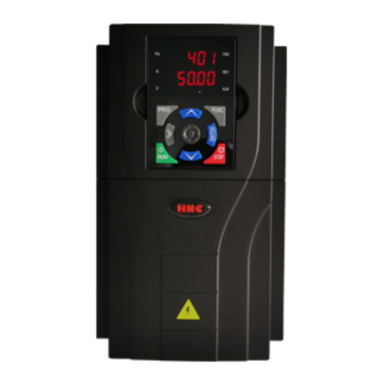
- Page 146 HV100 Series High Performance Current Vector Inverter Figure 2: Inverter...
-
Page 147: Warranty Agreement
HV100 Series High Performance Current Vector Inverter Warranty agreement 1 The warranty period of this product is 18 months (subject to the information of fuselage bar code). During the warranty period, if the product breaks down or is damaged under normal use according to the instruction manual, our company is responsible for free maintenance. - Page 148 HV100 Series High Performance Current Vector Inverter Edition: V4.0 Thanks for choosing HNC product. Any technique support, please feel free to contact our support team Tel: 86(20)84898493 Fax: 86(20)61082610 URL: www.hncelectric.com Email:support@hncelectric.com...
Need help?
Do you have a question about the HV100 Series and is the answer not in the manual?
Questions and answers
Alarm E-15