Advertisement
Quick Links
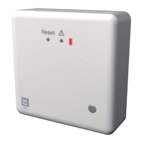
LK Receiver Unit Cq 1 (NC)
Models
LK Wireless Room Temperature Controller Cq
NC 1 consists of a LK Room Thermostat Cq
(transmitter) and a LK Receiver Unit Cq 1 (a re-
ceiver device for one channel).
Also included in the wireless assortment is a re-
ceiving device for eight channels; for more infor-
mation see separate instructions for LK Receiver
Unit Cq 8.
The LK Repeater Cq HW (signal repeater) is avai-
lable as an accessory for difficult sending condi-
tions; see more about this in separate instructions
for the LK Repeater-HW.
Functional description
The LK Room thermostat Cq-n regulates the tem-
perature of the room via transmission of radio
signals to the LK Receiver Unit Cq 1. The recei-
ver unit transforms the radio signals into control
signals which activate the LK Controlling Device.
Since the communication between the LK Re-
ceiver Unit Cq 1 and the LK Controlling Device
occurs via cable, it is most suitable to place the
receiver unit in direct connection to the circuit
distributor.
LK Room Thermostat Cq-n
LK Room Thermostat Cq-n is available in two
different models: polar white or silver grey.
The LK Room Thermostat Cq-n regulates the
temperature of the room via transmission of radio
signals to the LK Receiver Unit Cq 1. Regulation
occurs via pulse width modulated (PBM) regula-
tion which is especially adapted to thermoelectric
Assembly instructions | LK Receiver Unit Cq 1 (NC)
controlling devices. The control signal, which is
calculated from the difference between the real
and set temperatures, is emitted in the form of
a signal with different pulse and rest conditions.
The total of the signal and rest times is always 10
minutes. In the event of large differences in tem-
perature, the thermostat is constantly coupled on
or off.
Assembly of LK Room Thermostat Cq-n
Take apart the room thermostat by lifting the dial
at the temperature scale upwards and loosening
the screws which are visible. Unfold the upper
piece towards the left until it loosens. Install in
place according to the installation drawing.
To ensure proper functionality of the room ther-
mostat, the following points should be observed:
• Install the thermostat on an inner wall with
free ventilation, approximately 1.5 metres
above the floor.
• Avoid exposing the thermostat to direct sun-
light or other heat sources.
• Do not install the thermostat close to a radio,
TV or other senders.
• Installation of the thermostat in the vicinity
of metal doors, metal cabinets or similar is
unsuitable.
LK Receiver Unit Cq 1
LK Receiver Unit Cq 1 can address 1 LK room
thermostat Cq-n.
It is possible to connect two controlling devices
directly to Cq 1. With the help of an outer termi-
nal, a total of eight devices can be connected.
EN.33.C.74(NC).
1
Advertisement

Summary of Contents for LK Systems Cq 1 NC
- Page 1 Assembly instructions | LK Receiver Unit Cq 1 (NC) LK Receiver Unit Cq 1 (NC) Models LK Wireless Room Temperature Controller Cq NC 1 consists of a LK Room Thermostat Cq (transmitter) and a LK Receiver Unit Cq 1 (a re- ceiver device for one channel).
- Page 2 Assembly instructions | LK Receiver Unit Cq 1 (NC) The unit is complemented with a LK Transformer Programming / commissioning 230/24V AC (article order separately) 1. Activate the receiver unit Always begin programming by erasing all even- The controlling device moves once a day in order tual previous programming according to the be- to prevent valves from sticking in a closed posi- low:...
- Page 3 Assembly instructions | LK Receiver Unit Cq 1 (NC) 3. Confirm chosen channel Power failure When the thermostat has ”found” its channel the If power failure occurs, no data is lost, all pro- sound signal from Cq1 becomes silent and the in- gramming is saved.
- Page 4 Assembly instructions | LK Receiver Unit Cq 1 (NC) Technical data Notes Completely disturbance-free operation cannot Article name LK Reception Unit Cq 1 always be guaranteed with the technology av- Article no. 241 81 28 ailable today, which does not allow free use of Power supply 230 V 50 Hz frequency bands.