Advertisement
Quick Links
Advertisement

Related Manuals for Dimastech EasyXL

Summary of Contents for Dimastech EasyXL
- Page 1 DimasTech EasyXL Version 1.0 ASSEMBLY MANUAL...
-
Page 2: Contents Of The Kit
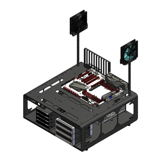
CONTENTS OF THE KIT... - Page 3 ASSEMBLY DimasTech EasyXL V.1.0 - FLEX-FAN - Align VC058 (10) to BT2501 (9) and fasten with No.1 screw VC047_M4x10 (22), as shown in Figure 1 - Align FAN 120 (item not included) to BT2501 (9) on vertical holes and fasten with No.2 screws VC050_M2,5x25...
- Page 4 ASSEMBLY DimasTech EasyXL V.1.0 – STEP-1 - Assemble No.4 VC067_rubber- feet_M4 (11) into the dedicated M4 threaded inserts, located at the base of the DIMAS_200_C_RF-RB_V.1.0 (1) body, as shown in the figure beside ASSEMBLY DimasTech EasyXL V.1.0 – STEP-2 - Unscrew the No.4 screws...
- Page 5 ASSEMBLY DimasTech EasyXL V.1.0 – STEP-3 - Unscrew the No.4 screws VC048_M3x10 housed in the back part of the DimasTech EasyXL V.1.0 and extract the two preassembled components BT051-2013 (5) and BT151 (6), as shown in the figure beside. ASSEMBLY DimasTech EasyXL V.1.0 – STEP-4...
- Page 6 ASSEMBLY DimasTech EasyXL V.1.0 – STEP-5 - The component BT149 (4) has the possibility to house inside No.4 hard-disks (items not included), the image has the sole purpose of illustrating the possible positions of the parts. - Insert No.16 VC019 (17) into the...
- Page 7 ASSEMBLY DimasTech EasyXL V.1.0 – STEP-7 - Insert the components BT148 (3), BT149 (4) with the respective hardware installed, inside the DimasTech EasyXL V.1.0 and fasten with the No.4 screws VC048_M3x10 previously extracted, as shown in the figure beside. The image has the sole purpose of illustrating the possible positions of the parts.
- Page 8 ASSEMBLY DimasTech EasyXL V.1.0 – STEP-9 - Align the slots at the base of the BT062-2013 component (7) with the slots at the back of the DimasTech EasyXL V.1.0 and fasten with No.2 screws VC047_M4x10 (22) plus No.2 knurled nuts VC024_M4 (19), as shown in the figure beside.
- Page 9 ASSEMBLY DimasTech EasyXL V.1.0 – STEP-11 - The DimasTech EasyXL V.1.0 has the possibility to mount No.9 spacers VC015_M3_25mm_M-F (16) in any of the No.22 M3 threaded holes available to you according to the type of motherboard you have purchased...
- Page 10 ASSEMBLY DimasTech EasyXL V.1.0 – PD019_19mm – Unscrew the hexagon nut of the pushbutton PD019_19mm (12), as shown in Figure 1 - Before proceeding with the assembly of the hardware parts, it is necessary to extract the BT148 (3) and BT149 components (4) as shown in STEP-2 and STEP-7.
- Page 11 ASSEMBLY DimasTech EasyXL V.1.0 – PD019_19mm For power ON or reset function, connect without polarity yellow cable to "NO1" and other Yellow cable to "C1", than to use the push button integrated LED, connect the black cable to "-" and the red cable to "+", push button integrated...
Need help?
Do you have a question about the EasyXL and is the answer not in the manual?
Questions and answers