Table of Contents

Related Manuals for Topdon ArtiLink200


Summary of Contents for Topdon ArtiLink200
- Page 1 If you have any questions or doubts, please contact us via Hotline (+86) 0755-23576169 Email support@topdondiagnostics.com Website www.topdondiagnostics.com Facebook @TopdonOfficial Twitter @TopdonOfficial ArtiLink200 Code Reader USER MANUAL...
-
Page 2: Table Of Contents
Content Welcome About Package List Compatibility General Information of OBDII Features Operation Introduction Technical Specification Warranty Warnings Cautions... -
Page 3: Welcome
Welcome Thank you for purchasing TOPDON ArtiLink200 code reader. Please take time to read and understand this User Manual before operating this product. About ArtiLink200, featuring codes reading/clearing, the check engine light English turning off, I/M readiness status checking, freeze frame data viewing and... -
Page 4: Compatibility
When a problem is detected, the OBDII system turns on a warning lamp (MIL) on the vehicle Please be noted that ArtiLink200 works on most 1996 US-based, 2000 instrument panel to alert the driver typically by the phrase of “Check Engine”... - Page 5 3.Location of the Data Link Connector (DLC) within a vehicle. OBDII Diagnostic Trouble Codes consist of a five-digit alphanumeric code. The first character, a letter, identifies which control The DLC (Data Link Connector or Diagnostic Link Connector) is the system sets the code. The other four characters, all numbers, provide standardized 16-cavity connector where diagnostic code readers additional information on where the DTC originated and the operating interface with the vehicle's on-board computer.
- Page 6 4.OBDII Readiness Monitors Comprehensive Components (CCM) Once the vehicle is running, the OBDII system is continuously checking An important part of a vehicle’s OBDII system is the Readiness Monitors, the above components, monitoring key engine sensors, watching for which are indicators used to find out if all of the emissions components engine misfire, and monitoring fuel demands.
- Page 7 5.OBDII Monitor Readiness Status In order for the OBD monitor system to become ready, the vehicle should be driven under a variety of normal operating conditions. These OBDII systems must indicate whether or not the vehicle’s PCM’s monitor operating conditions may include a mix of highway driving and stop and system has completed testing on each component.
- Page 8 problem and flashing is intended to discourage vehicle operation. The monitors so that future faults can be detected. Drive cycles vary vehicle onboard diagnostic system cannot turn the MIL off until the depending on the vehicle and the monitor that needs to be reset. For necessary repairs are completed or the condition no longer exists.
-
Page 9: Features
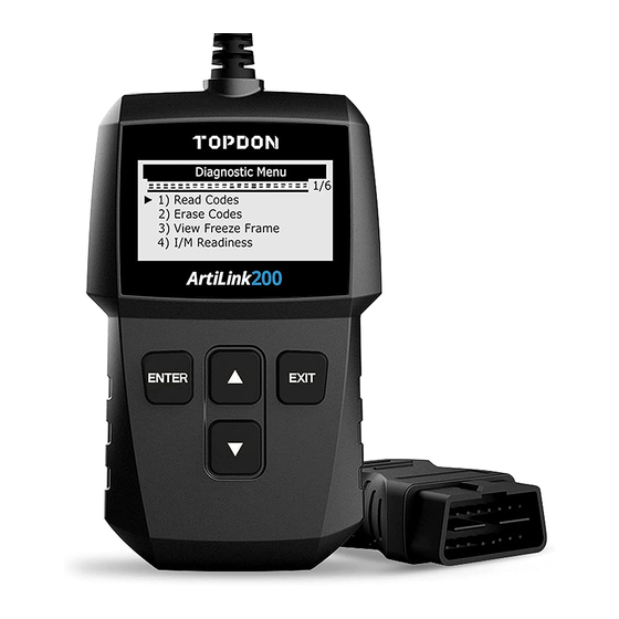
Features Buttons Operation ▲ Page up, or increase the battery rating values ▼ Page down, or decrease the battery rating values ENTER Confirm; Enter and proceed EXIT Cancel; Return to the previous page Connects the code reader to the vehicle’s 16-pin Connector Data Link Connector (DLC) -
Page 10: Operation Introduction
Operation Introduction 1.Setup The code reader allows you to make the following adjustments and Connect ArtiLink200 with your vehicle. settings: Turn the ignition off. Language: Selects desired language. Locate the vehicle’s 16-pin Data Link Connector (DLC). Unit of measure: Sets the unit of measure to English or Metric. - Page 11 2.Reading Codes ▲ ▼ On Main Menu, press and hold the “ ” or “ ” button to select the “Read Codes”, then press “ENTER” to continue. View DTCs and their definitions on screen. If more than one module is detected, you will be prompted to select a ▲...
- Page 12 NOTE: The control module number, sequence of the DTCs, total number Press and hold the “EXIT” to return. of codes detected and type of codes (Generic or Manufacturer specific, Stored or Pending codes) will be observed on the upper right hand corner of the display.
- Page 13 4.Viewing Freeze Frame Data Choose “YES” to confirm erasing. ▲ ▼ Press and hold the “ ” or “ ” to select “View Freeze Frame” on “Diagnostic Menu” and press “ENTER” to continue. If you want to proceed with erasing the codes, press “ENTER” button to erase.
- Page 14 If the retrieved information covers more than one screen, press and ▲ ▼ hold the “ ” or “ ” until all data have been shown up. Wait a few seconds while the code reader validates the PID MAP. Press and hold the “EXIT” to return.
- Page 15 5.Retrieving I/M Readiness Status completed its diagnostic testing. I/M Readiness function is used to check the operations of the Emission “N/A” -- The monitor is not supported on that vehicle. System on OBDII compliant vehicles. ▲ ▼ Press and hold the “ ”...
- Page 16 If the vehicle supports both types of tests, then both types shows on the screen for selection. Wait a few seconds while the code reader validates the PID MAP. ▲ ▼ Press and hold the “ ” or “ ” to view the status of the MIL light (“ON” or “OFF") and the following monitors: Misfire monitor -- Misfire Monitor Fuel System Mon -- Fuel System Monitor...
- Page 17 Oxygen Sens Mon -- O2 Sensors Monitor If the vehicle supports readiness test of “This Drive Cycle”, a screen of the following will be displayed: Catalyst Mon -- Catalyst Monitor EVAP System Mon -- Evaporative System Monitor Oxygen Sens htr --O2 Sensor Heater Monitor Sec Air System -- Secondary Air Monitor Htd Catalyst -- Heated Catalyst Monitor A/C Refrig Mon -- A/C System Monitor...
- Page 18 6.Viewing Vehicle Information Wait a few seconds or press “ENTER” button to continue. The Vehicle Info. function enables retrieval of the Vehicle Identification No. (VIN), Calibration ID(s), Calibration Verification Nos. (CVNs) and In- use Performance Tracking on 2000 and newer vehicles that support Mode 9.
- Page 19 ▲ ▼ From “Vehicle Info” menu, press and hold the “ ” or “ " to select an Press and hold the “EXIT” to return. available item to view and press “ENTER”. 7.Exiting OBDII Test Press and hold “EXIT” button to exit OBDII test, a warning message comes up asking your confirmation.
-
Page 20: Technical Specification
Display: Backlight, 128 * 64 pixel display TOPDON One Year Limited Warranty Operating Voltage: 9~16V The TOPDON Company warrants to its original purchaser that TOPDON products will be free from defects in material and workmanship for 12 Operating Current: 40~50mA months from the date of purchase (Warranty Period). -
Page 21: Warnings
Warnings Cautions Always perform automotive testing in a safe environment. Please ensure that the vehicle battery is fully charged and the tools are closely connected to the vehicle DLC to avoid erroneous data DO NOT smoke near the vehicle during testing. generated by tools and diagnostic systems. -
Page 22: Faq
Q: How to change the language? A: Press and hold “EXIT” to enter “Setup”, then choose “Language”. Q: Why system halts when reading data stream? A: It may be caused by a slackened connector. Please turn off the tool, Q: How to change the Metric system to British system? firmly connect the connector, and switch it on again.
Need help?
Do you have a question about the ArtiLink200 and is the answer not in the manual?
Questions and answers