
Related Manuals for Acromet 2500 Series


Summary of Contents for Acromet 2500 Series
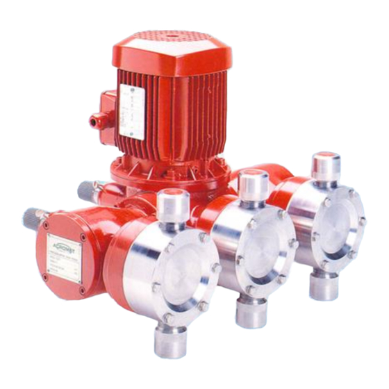
- Page 1 COMPACT DESIGN TOTALLY ENCLOSED OIL IMMERSED MECHANISM MANUAL OR AUTO ADJUSTMENT SERIES 2500 METERING PUMPS 2500 001 TO 050 METERING PUMP MODEL _____________________ SERIAL NO __________________...
- Page 2 1250 -025 -050 LABORATORY ACCURACY INDUSTRIAL DURABILITY The 2500 Series offers accurate, competitively priced, chemical metering for all applications. Multiplexed designs with choice of liquid end sizes and material of construction. Available with or without motor. Motor mount flange to suit D71 metric motors.
- Page 3 MP2500 Updated January 2017 Metering Pump Series 2500...
-
Page 4: Table Of Contents
Suction & Discharge Valves ..............8 Diaphragm .................... 9 TROUBLESHOOTING ................10 2500 SERIES METERING PUMP ............13 Drive End (Simplex) – Side Elevation ............13 Drive End (Simplex) – Side Elevation - Parts List ........14 Drive End (Simplex) – End Elevation ............15 Drive End (Simplex) –... -
Page 5: Safety
MP2500 Updated January 2017 METERING PUMPS 2500 SERIES SAFETY General Please read and familiarise yourself with all sections of this and other equipment manuals before proceeding with installation. Observe all standard precautions which apply to moving machinery. Observe all standard precautions which apply to electrical equipment, drives and controls. -
Page 6: Introduction
MP2500 Updated January 2017 INTRODUCTION Acromet metering pumps are designed and manufactured for long, low maintenance service life and when properly applied, will give many years of consistent accurate metering and trouble free operation. The following instructions should be read and followed to correctly install and operate the pump and ensure optimum pump life and performance. -
Page 7: Suction
MP2500 Updated January 2017 4.1.4 Piping should be as short and straight as possible and arranged to avoid loops or pockets where gas may accumulate. 4.1.5 All piping should be separately supported close to the pump to avoid imposing pipe loads on the pump. When handling high or low temperature liquids, measures should be taken to prevent distortion of piping imposing loads on the pump. -
Page 8: Discharge
MP2500 Updated January 2017 Discharge 4.3.1 Should it be necessary to install an isolating valve in the discharge line, a relief valve must be installed between the pump and isolating valve. 4.3.2 The 2500 Metering Pump, being a positive displacement pump, will be damaged if operated against a closed valve. -
Page 9: Piping Arrangement
MP2500 Updated January 2017 Piping Arrangement WRONG CORRECT Should it be necessary to install an isolating valve in the discharge line, a relief valve must be installed in the line between the pump and isolating valve. Metering pumps are positive displacement pumps and produce pulsating flow. Consequently there is considerable line pressure loss and suction piping should be sized to ensure adequate NPSHA. -
Page 10: Operation
MP2500 Updated January 2017 OPERATION Before Starting 5.1.1 Ensure the pump will be operated within its specification. 5.1.2 Check gearbox oil level. Prior to leaving factory, each pump is filled to the correct level with the recommended grade of oil (see maintenance section). -
Page 11: Capacity Adjustment
MP2500 Updated January 2017 CAPACITY ADJUSTMENT Standard manual capacity adjustment is by means of a micrometer. multiplex pumps, each pump head is individually controlled by a micrometer located behind the respective pump head. Adjustment should be made whilst the pump is running. To adjust whilst stopped will cause damage to the pump mechanism. -
Page 12: Maintenance
ETERING RETURNED FOR MAINTENANCE THAT HAS NOT BEEN SUITABLY CLEANED It is an Acromet Quality Assurance policy that all equipment returned for repair or service be supplied with a completed copy of the 'Equipment Decontamination Advice' form, as shown on page 37 of this manual. -
Page 13: Diaphragm
After the new diaphragm has been fitted, calibration should be checked and monitored until diaphragm has stabilised. All major mechanical repairs should be undertaken by Acromet's specialist servicing workshop in Melbourne. In most cases a pump can be repaired and despatched in one day. -
Page 14: Troubleshooting
MP2500 Updated January 2017 TROUBLESHOOTING Trouble Cause Corrections Pump does not start. Blown electrical. Fuse. Check cause and change to suitable capacity fuse Electrical overload relay Change relay capacity to trips. correct value. Electrical wiring breakdown Change or reconnect. or defective contact. Low voltage. - Page 15 MP2500 Updated January 2017 Trouble Cause Corrections Reduced pump flow Valve clogged. Clean. rate or unstable rate. Worn valve seat. Replace seat or valve. Flow meter incorrect. Inspect meter, repair or change. Leakage from relief valve. Inspect, repair or change. Air leaking into suction Check for leak source and piping...
- Page 16 MP2500 Updated January 2017 Trouble Cause Correction Excessive pump flow Pressure difference across Increase pressure rate. pump less than 20 KPa difference (ie install back Flow continues after pressure valve). pump has stopped. Discharge line too long or Reduce length and/or diameter too small increase diameter.
-
Page 17: Drive End (Simplex) - Side Elevation
MP2500 Updated January 2017 2500 SERIES METERING PUMP Drive End (Simplex) – Side Elevation Page 13 Series 2500... -
Page 18: Drive End (Simplex) - Side Elevation - Parts List
MP2500 Updated January 2017 Drive End (Simplex) – Side Elevation - Parts List ITEM PART NO DESCRIPTION NOTES E-42 WORM ◊ 10-01-11 (DRIVE MOTOR) 08-12-02 OIL FILL PLUG 10354 WORM EXTENSION SHAFT □ 10302 PRIMARY PISTON 11-01-21 CIRCLIP (STRIKER SHAFT) 09/03/06 WAVE WASHER 10311... -
Page 19: Drive End (Simplex) - End Elevation
MP2500 Updated January 2017 Drive End (Simplex) – End Elevation Page 15 Series 2500... -
Page 20: Drive End (Simplex) - End Elevation - Parts List
MP2500 Updated January 2017 Drive End (Simplex) – End Elevation - Parts List ITEM PART NO DESCRIPTION NOTES 08-01-74 SCREW (MOTOR) 09-02-24 SPRING WASHER (MOTOR) 10355 WORM WHEEL ◊ 06-04-07 BUSH (MAIN SHAFT) 10325-1 MAIN SHAFT 08-12-02 DRAIN PLUG AS SPEC DRIVE MOTOR 10351(1)1-5... -
Page 21: Liquid Head Section Drawings
MP2500 Updated January 2017 Liquid Head Section Drawings Page 17 Series 2500... - Page 22 MP2500 Updated January 2017 This section drawing applies to liquid head sizes -001 manufactured in 316SS from February 2014 with serial numbers starting with 1402-00000-0 and higher. Page 18 Series 2500...
- Page 23 MP2500 Updated January 2017 Page 19 Series 2500...
- Page 24 MP2500 Updated January 2017 Page 20 Series 2500...
- Page 25 MP2500 Updated January 2017 Page 21 Series 2500...
- Page 26 MP2500 Updated January 2017 Page 22 Series 2500...
- Page 27 MP2500 Updated January 2017 Page 23 Series 2500...
- Page 28 MP2500 Updated January 2017 Page 24 Series 2500...
- Page 29 MP2500 Updated January 2017 Page 25 Series 2500...
- Page 30 MP2500 Updated January 2017 Page 26 Series 2500...
- Page 31 MP2500 Updated January 2017 Page 27 Series 2500...
- Page 32 MP2500 Updated January 2017 Page 28 Series 2500...
- Page 33 MP2500 Updated January 2017 Page 29 Series 2500...
-
Page 34: Calibration Of A Metering Pump
MP2500 Updated January 2017 CALIBRATION OF A METERING PUMP To perform a calibration test on the delivery rate you will require a stop watch and materials necessary to perform a series of simple calculations. To utilise this system efficiently, the following procedure should be followed whilst the pump is operating. -
Page 35: Calibration Cylinder - Installation Guide
MP2500 Updated January 2017 CALIBRATION CYLINDER – INSTALLATION GUIDE LOCATION: Install the calibration cylinder as shown in Figure 1. The cylinders must be installed in the suction piping in a vertical position and as close as possible to the suction tank. Remember the location should make allowance for sufficient free space around the calibration cylinder for easy reading of graduations. -
Page 36: Series 500 Valve Instructions
Valve operating pressure is controlled by the spring (8) and can be increased or decreased by varying the spring preload. At date of purchase, Acromet will adjust the valve to meet customer's requirements. To alter or set operating pressure at site, it is necessary for a pressure gauge with... - Page 37 MP2500 Updated January 2017 TYPICAL INSTALLATION LAYOUT 1. Supply Tank 2. Metering Pump 3. Pressure Relief Valve 4. Pulsation Dampener 5. Back Pressure Valve 6. Pressure Gauge 7. De-pressurising Valve Page 33 Series 2500...
- Page 38 MP2500 Updated January 2017 GENERAL ASSEMBLY 502 SERIES BACK PRESSURE VALVE Page 34 Series 2500...
- Page 39 MP2500 Updated January 2017 GENERAL ASSEMBLY 502 SERIES PRESSURE RELIEF VALVE Page 35 Series 2500...
-
Page 40: Equipment Decontamination Advice Doc. No. Sd-19.0-1
MP2500 Updated January 2017 This Page Left Blank Page 36 Series 2500... -
Page 41: Appendix
MP2500 Updated January 2017 APPENDIX EQUIPMENT DECONTAMINATION ADVICE DOC. No. SD-19.0-1 Page 35 Series 2500... - Page 42 MP2500 Updated January 2017 Page 37 Series 2500...
- Page 43 MP2500 Updated January 2017 Page 37 Series 2500...
Need help?
Do you have a question about the 2500 Series and is the answer not in the manual?
Questions and answers