Table of Contents
Advertisement
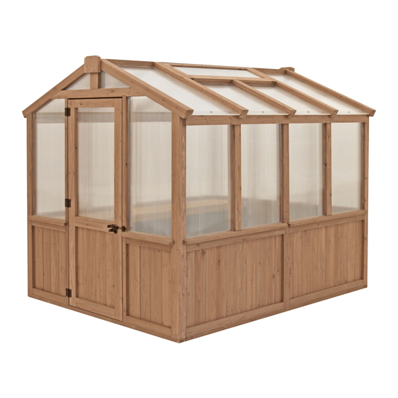
2.03m (6.6 ft) x 2.38m (7.8 ft)
CEDAR POLY GREENHOUSE
Installation and Operating Instructions – YM12842
YM12842 - 6.6' x 7.8'
HEIGHT:
Cedar Poly Greenhouse
2.36m / 7' 9"
IMPORTANT, RETAIN FOR FUTURE REFERENCE: READ CAREFULLY
07-08-2021
7'10 5/16"
2.395 m
2.395 m
7' 10-5/16"
Yardistry – North America
Toll Free Customer Support:
1.888.509.4382
2.049 m
6'8 11/16"
info@yardistrystructures.com
2.049 m
6' 8-11/16"
www.yardistrystructures.com
Regular Hours: Mon - Fri, 8:30 am - 5:00
pm EST (excl. holidays)
(For extended hours see our website)
English and French Spoken
Patents Pending
Y40000-842
Advertisement
Table of Contents

Related Manuals for Yardistry YM12842


Summary of Contents for Yardistry YM12842
- Page 1 2.03m (6.6 ft) x 2.38m (7.8 ft) CEDAR POLY GREENHOUSE Installation and Operating Instructions – YM12842 YM12842 - 6.6' x 7.8' HEIGHT: Cedar Poly Greenhouse 2.36m / 7’ 9” IMPORTANT, RETAIN FOR FUTURE REFERENCE: READ CAREFULLY 07-08-2021 7'10 5/16" 2.395 m 2.395 m...
- Page 2 Wood is NOT flame retardant and will burn. Grills, fire pits and chimineas are a fire hazard if placed too close to a Yardistry structure. Consult user’s manual of the grill, fire pit or chiminea for safe distances from combustible materials.
- Page 3 Limited Warranty Yardistry warrants that this product is free from defect in materials and workmanship for a period of one (1) year from the original date of purchase. In addition, for any product with lumber, all lumber is warranted for five (5) years against rot and decay. Polycarbonate panels are warranted for five (5) years against defect in materials and workmanship.
- Page 4 If you dispose of your Yardistry structure: Please disassemble and dispose of your unit so that it does not create any unreasonable hazards at the time it is discarded. Be sure to follow your local waste ordinances.
- Page 5 Assembly Tips Following are some helpful tips to make the assembly process smooth and efficient. PRE-ASSEMBLIES: • Work on a raised, solid and flat surface such as, a table or saw horse. • Keep all connections flush where shown in the instructions. •...
- Page 6 Sealant Application Tips, Warning and First Aid Information SEALANT: • All surfaces to be clean, dry, dust and grease free before application with temperatures above 5 ° C (41 ° F), no warmer than 35 ° C (95 ° F). •...
- Page 7 Structure Location Preparation Note: It is critically important you start with square, solid and level base to attach your Greenhouse. Preparing the Location for your Structure (replaces Permanent Installation Examples) Note: It is critically important to start with a square, solid and level base to attach your Greenhouse The hardware to mount the structure permanently will need to be purchased separately at your local hardware store.
- Page 8 Part Identification ( Dimensions are approximate and are shown to assist in the identification of parts for assembly. Actual dimensions may be smaller or larger. 2pc. (1108) - Left Post FSC 66.7 x 76.2 x 1835.2mm (72-1/4") Y50229-1108 2pc. (1109) - Y50229-1109 Right Post FSC 66.7 x 76.2 x 1835.2mm (72-1/4") 1pc.
- Page 9 Part Identification ( Dimensions are approximate and are shown to assist in the identification of parts for assembly. Actual dimensions may be smaller or larger. 2pc. (1113) - Back Post FSC 76.2 x 66.7 x 1974.9mm (77-3/4") Y50229-1113 1pc. (1120) - Back Base FSC 38.1 x 66.7 x 1905mm (75") Y50229-1120 1pc.
- Page 10 Part Identification ( Dimensions are approximate and are shown to assist in the identification of parts for assembly. Actual dimensions may be smaller or larger. 2pc. (1110) - Mid Post FSC 66.7 x 76.2 x 1835.2mm (72-1/4") Y50229-1110 2pc. (1118) - Side Base FSC 38.1 x 76.2 x 2190.8mm (86-1/4") Y50229-1118 4pc.
- Page 11 Part Identification ( Dimensions are approximate and are shown to assist in the identification of parts for assembly. Actual dimensions may be smaller or larger. 1pc. (1187) - Vent Roof Panel Block FSC 15.9 x 38.1 x 1003.3mm (39-1/2") Y50229-1187 2pc.
- Page 12 Part Identification ( Dimensions are approximate and are shown to assist in the identification of parts for assembly. Actual dimensions may be smaller or larger. 8pc. (1138) - Wooden Gusset FSC 34.9 x 139.7 x 203.2mm (8") Y50229-1138 2pc. (1139) - Short Upper Shelf FSC 15.9 x 101.6 x 1822.5mm (71-3/4") Y50229-1139 2pc.
- Page 13 Part Identification ( Dimensions are approximate and are shown to assist in the identification of parts for assembly. Actual dimensions may be smaller or larger. 1pc. 1pc. (2PK) Right F/B Side Panel Back Centre Panel 1pc. (2PK) Left F/B Side Panel (Y61800-429) (Y70800-427) (Y70800-428)
- Page 14 Hardware Identification ( Dimensions are approximate and are shown to assist in the identification of parts for assembly. Actual dimensions may be smaller or larger. #10 x 4" 65pc. Wood Screw - (Y06091-740) #10 x 5-5/8" 10pc. Wood Screw - (Y06091-758) 18pc.
- Page 15 • Please retain this information for future reference. You will need this information if you contact the Consumer Relations Department. PRODUCT NUMBER: YM12842 CARTON I.D. STAMP: __ __ __ __ __ ___ (Box 1) CARTON I.D. STAMP: __ __ __ __ __ ___ (Box 2)
- Page 16 STOP STOP STOP STOP IMPORTANT! POLYCARBONATE INFORMATION • Each polycarbonate panel has a UV coating on only ONE (1) side of the panel. STOP PAGE/IMPORTANT – Polycarbonate • To install properly so the UV coating is on the outside of the panel, the notch in the panel needs to be oriented to the bottom right-hand side of the assembly when on •...
- Page 17 • To install properly so the UV coating is on the outside of the panel, orientated to the bottom right-hand corner of the assembly STOP STOP STOP STOP IMPORTANT! ANTI-DUST TAPE INFORMATION • Photo of PC Sheet and a make note of the small notch on bottom ri •...
- Page 18 Step 2: Front Wall Assembly Part 1 F2.1 A: At the bottom of one (1108) Left Post and one (1109) Right Post attach one (1119) Front Base with two #10 x 4” Wood Screws per post. Make sure (1109) grooves in posts are facing inwards Right Post and to the back.
- Page 19 Step 2: Front Wall Assembly Part 2 (1111) Left F2.4 B: In the grooves of each post slide one Door Post (1147) FB Panel down so they rest tight to the top of the (1119) Front Base. (F2.4) C: Place one (1111) Left Door Post and one (1112) Right Door Post tight to each (1112) Right (1147) FB Panel then attach to (1119)
- Page 20 Step 2: Front Wall Assembly Part 3 D: Attach (1111) Left Door Post and (1112) Right Door Post to (1147) FB Panel with one #8 x 3” Wood Screw per post. (F2.6 and F2.7) E: Attach (1119) Front Base to (1147) FB Panels with three #8 x 3” Wood Screws per panel. (F2.6 and F2.8) (1112) Right Door Post F2.6...
- Page 21 Step 2: Front Wall Assembly Part 4 #10x 4” Wood Screws Connects Right and Left Posts to FB Wall F: Attach (1108) Left Post and (1109) Right Post to top and bottom of (1147) FB Panel with two #10 x 4” Wood Screws per post.
- Page 22 Step 2: Front Wall Assembly Part 5 G: Place one (1105) Front Wall Sill on top of each (1147) FB Panel. Use one (1188) Guide Spacer in the grooves of each post and (1105) Front Wall Sill to line up Posts with Door Posts. Attach (1105) Front Wall Sills to (1147) FB Panels with two #8 x 3”...
- Page 23 Step 2: Front Wall Assembly Part 6 Remove film from both sides of Left FB Side Panel and Right FB Side Panel. H: Refer to pages 16 and 17 and apply top and bottom tape to Left FB Side Panel and Right FB Side Panel. I: In the grooves of Posts and Door Posts slide Left FB Side Panel and Right FB Side Panel down so they rest in the grooves of (1105) Front Wall Sill.
- Page 24 Step 2: Front Wall Assembly Part 7 J: Place (1143) Front Gable Beam on top of (1111) Left Door Post and (1112) Right Door Post so notches on the bottom fit over the posts then attach with two #10 x 4” Wood Screws per post. (F2.15 and F2.16) F2.15 (1143) Front Gable Beam...
- Page 25 FOR SEPARATION OF UPRIGHTS Step 2: Front Wall Assembly INSIDE AND OUT. Part 8 K: Place one (1121) Upright Inside and one (1122) Upright Outside centred on the top of (1143) Front Gable Beam. Use one (1188) Guide Spacer in the grooves of (1143) Front Gable Beam for proper spacing of Uprights. Attach Beam to Uprights with one #10 x 4”...
- Page 26 Step 2: Front Wall Assembly Part 9 Remove film from both sides of Gable Panel. L: Refer to pages 16 and 17 and apply top and bottom tape to Gable Panel. M: Slide Gable Panel down into the grooves of (1143) Front Gable Beam, in between (1121) Upright Inside and (1122) Upright Outside.
- Page 27 Step 2: Front Wall Assembly Part 10 N: Place one (1115) Right Roof Rafter and one (1116) Left Roof Rafter on each side of the frame so the ends overhang (1108) Left Post and (1109) Right Post by 1-1/2” (3.81 cm). They will sit on the uprights. Make sure grooves in rafters face inwards.
- Page 28 Step 3: Back Wall Assembly Part 1 #10 X 4” Wood Screws Connects BACK BASE to RIGHT AND LEFT POSTS F3.1 A: At the bottom of one (1108) Left Post and one (1109) Right Post attach one (1120) Back Base with two #10 x 4”...
- Page 29 Step 3: Back Wall Assembly Part 2 (1113) Back Post B: In the grooves of each post slide one (1147) FB Panel down so they rest tight to F3.4 the top of the (1120) Back Base. (F3.4) C: Place one (1113) Back Post tight to each (1147) FB Panel then attach to (1120) Back Base with two #10 x 4”...
- Page 30 Step 3: Back Wall Assembly Part 3 D: Attach (1108) Left Post, (1109) Right Post to each (1147) FB Panel with two #10 x 4” Wood Screws per post and each (1113) Back Post to each (1147) FB Panel with one #10 x 4” Wood Screw per post. (F3.6 and F3.7) E: Attach (1120) Back Base to (1147) FB Panels with three #8 x 3”...
- Page 31 Step 3: Back Wall Assembly Part 4 F: In the grooves of each (1113) Back Post slide one (1155) Vent Wall Panel down so it rests tight to the top of the (1120) Back Base. Vent should be closer to the (1120) Back Base. (F3.8 and F3.9) (1113) F3.8 Back Post...
- Page 32 Step 3: Back Wall Assembly Part 5 G: Attach (1120) Back Base to (1155) Vent Wall Panel F3.11 (1108) with three #8 x 3” Wood Screws. (F3.10 and F3.12) (1113) Left Post Back Post (1109) H: Place one (1106) Back Wall Sill on top of (1155) Vent Right Post Wall Panel and each (1147) FB Panel so the notches fit (1188) Guide...
- Page 33 Step 3: Back Wall Assembly Part 6 Remove film from both sides of Left FB Side Panel, Right FB Side Panel Back Centre Panel and Back Centre Panel. Right FB Left FB Side Side Panel Panel F3.15 I: Refer to pages 16 and 17 and apply Outside View top and bottom tape to Left FB Side Panel, Right FB Side Panel and Back...
- Page 34 #10 X 4” Wood Screws Step 3: Back Wall Assembly CONNECT UPRIGHT INSIDE AND OUTSIDE TO THE BACK GABLE Part 7 BEAM K: Place one (1121) Upright Inside and one (1122) Upright Outside centred on the top of (1117) Back Gable Beam.
- Page 35 CONNECT THE GABLE Step 3: Back Wall Assembly TO THE BACK POSTS Part 8 L: Place (1117) Back Gable Beam on top of (1113) Back Posts so notches on the bottom fit over the posts then attach with two #10 x 4” Wood Screws per post. (F3.17 and F3.18) F3.17 (1117) Back Gable Beam...
- Page 36 Step 3: Back Wall Assembly Part 9 Remove film from both sides of Gable Panel. M: Refer to pages 16 and 17 and apply top and bottom tape to Gable Panel. N: Slide Gable Panel down into the grooves of (1117) Back Gable Beam, in between (1121) Upright Inside and (1122) Upright Outside.
- Page 37 Step 3: Back Wall Assembly Part 10 O: Place one (1115) Right Roof Rafter and one (1116) Left Roof Rafter on each side of the frame so the ends overhang (1108) Left Post and (1109) Right Post by 1-1/2” (3.81 cm). They will sit on the uprights. Make sure grooves in rafters face inwards.
- Page 38 VENT WALL PANEL Step 3: Back Wall Assembly Part 11 Q: On the inside of the frame attach four (1136) Inside Vent Trims around opening in (1155) Vent Wall Panel using two #8 x 2-1/2” Wood Screws per trim. (F3.25 and F3.26) F3.25 Inside View (1136) Inside...
- Page 39 Notice holes in SIDE BASE are orientated to the top edge. Step 4: Side Wall Assembly Part 1 #10 X 4” Wood Screws Notice the angle of the MID POST top end, angles down Connects SIDE BASE to MID POST #10 X 4”...
- Page 40 Step 4: Side Wall Assembly Part 2 B: On each side of (1110) Mid Post, in the grooves, slide one (1152) Side Wall Panel down so they rest tight to the top of the (1118) Side Base. Ends of (1118) Side Base and each (1152) Side Wall Panel should be flush. The tongue of the panel will overhang the base.
- Page 41 Step 5: Connect Wall Assemblies Part 1 If using a treated lumber base it should F5.1 (1108) Back Wall be placed in the final location. Images Left Post Inside View Assembly will only show treated lumber base. Same instructions apply for concrete base, unless otherwise specified.
- Page 42 Step 5: Connect Wall Assemblies Part 2 Front Wall F5.4 Assembly Side Wall Assembly B: With a helper, stand up Front Wall Assembly and slide so Side Wall (1109) Assemblies fit into grooves of (1108) Left Right Post Post and (1109) Right Post. Pre-drill with a Slide the tongue from the SIDE WALL 1/8”...
- Page 43 Step 6: Square Assembly A: Make sure assembly is square and the diagonal distance from the inside of one post to the inside of the opposite post is 9’ 2-7/16” (2.806 m). (F6.1) 7'7 1/2" 2.324 m Outside Post Side Wall Assembly Outside Post F6.1...
- Page 44 Step 7: Attach Side Wall Sills A: Place one (1107) Side Wall Sill on top of each (1152) Side Wall Panel. Use one (1188) Guide Spacer in the grooves of each post and (1107) Side Wall Sill to line up posts with (1110) Mid Posts. Attach (1107) Side Wall Sills to (1152) Side Wall Panels with three #8 x 3”...
- Page 45 Step 8: Attach Corner Brackets Part 1 A: On the inside of the assembly, using one Corner Bracket per corner connect (1119) Front Base and (1120) Back Base to (1118) Side Bases with two #10 x 1-1/4” Pan Screws per bracket. (F8.1 and F8.2) F8.1 (1119) #10 X 1-1/4”...
- Page 46 Step 8: Attach Corner Brackets Part 2 (1110) Mid (1109) Right Post Post F8.3 B: On the inside of the assembly, (1108) Left underneath each (1107) Side Wall Sill, Post using one Corner Bracket per corner connect each (1108) Left Post, (1109) Right Post and (1110) Mid Post to each (1107) Side Wall Sill with two #10 x 1-1/4”...
- Page 47 Step 9: Secure Assembly to Base A: Using the purchased hardware as mentioned on page 7, pre-drill then secure the Front Wall, Back Wall and Side Walls to the base in the locations shown in F9.1. F9.1 Front Wall Assembly Back Wall Assembly Side Wall...
- Page 48 #8 X 2-1 Step 10: Attach Side Wall Top Connec POST (L A: On each Side Wall Assembly place one (1125) Side Wall Top tight to bottom of (1115) Right Roof Rafters and (1116) Left Roof Rafters, so notches are at the top. Centre notch to be flush to the top of (1110) Mid Post. Attach (1125) Side Wall Top to (1108) Left Posts and (1109) Right Posts with one #8 x 2-1/2”...
- Page 49 Step 11: Side Wall Panel Assembly Part 1 (1108) Remove film from both sides of Side Wall Panels. Left Post F11.1 Side Wall A: Refer to pages 16 and 17 and apply top and bottom Panel tape to Side Wall Panels. B: Put Side Wall Panel in the grooves of (1107) Side Wall Sill then slide into grooves of Left and Right Posts.
- Page 50 Step 11: Side Wall Panel Assembly Part 2 C: Slide one (1144) Short Post Assembly down along the (1144) Short F11.4 Post Assembly sides of each Side Wall Panel so they fit in the notches of (1125) Side Wall Tops. Dowel is at the bottom and fits in (1125) (1107) Side Wall Sills.
- Page 51 Step 11: Side Wall Panel Assembly Part 3 Remove film from both sides of Side Wall Panels. E: Refer to pages 16 and 17 and apply top and bottom tape to Side Wall Panels. F: In the grooves of (1144) Short Post Assemblies and (1110) Mid Posts slide Side Wall Panels down to fit in the grooves of (1107) Side Wall Sills.
- Page 52 Step 11: Side Wall Panel Assembly Part 4 G: On the top of each Side Wall Panel place one PC U-Channel. (F11.9 and F11.10) H: Attach each Side Wall Panel to (1125) Side Wall Tops using three #10 x 1-1/4” Black Pan Screws with EPDM washers per panel.
- Page 53 Step 12: Roof Peak Assembly Part 1 A: Place three (1114) Middle Roof Rafters in the notches of (1123) Roof Peak. Angled end of rafters tight to (1123) Roof Peak. Groove of (1123) Roof Peak is towards the top of the board and grooves in (1114) Middle Roof Rafters face the sides and should line up with grooves in (1123) Roof Peak.
- Page 54 Step 12: Roof Peak Assembly Part 2 B: Flip the assembly over then attach each (1114) Middle Roof Rafter to (1123) Roof Peak with one #10 x 4” Wood Screw per rafter. Screws are installed at an angle. (F12.3) (1123) Roof Peak F12.3 #10 x 4”...
- Page 55 Step 13: Vent Roof Peak Assembly Part 1 A: Place two (1114) Middle Roof Rafters in notches of (1124) Vent Roof Peak. Angled end of rafters tight to (1124) Vent Roof Peak. Groove of (1124) Vent Roof Peak is towards the top of the board and grooves in (1114) Middle Roof Rafters face the sides and should line up with the groove in (1124) Vent Roof Peak.
- Page 56 Step 13: Vent Roof Peak Assembly Part 2 C: Flip the assembly over then on the inside of each (1114) Middle Roof Rafter, place one (1126) Inside Vent Block with angled end tight to the top of (1124) Vent Roof Peak and sides flush to the top of each rafter. Attach (1126) Inside Vent Block to (1114) Middle Roof Rafters with three #8 x 2”...
- Page 57 Step 13: Vent Roof Peak Assembly Part 3 D: Tight to the top of (1126) Inside Vent Blocks, with grooves facing down, place (1128) Bottom Vent Block. Use (1188) Guide Spacers in grooves of (1114) Middle Roof Rafters and (1128) Bottom Vent Block for accurate positioning then attach rafters to block with one #10 x 4”...
- Page 58 Step 13: Vent Roof Peak Assembly Part 4 E: On the bottom of the (1170) Vent Roof Panel, flush to the bottom board and centred on the panel, attach (1187) Vent Roof Panel Block with three #8 x 1-1/4” Wood Screws. (F13.7 and F13.8) (1170) Vent F13.7 Roof Panel...
- Page 59 Step 13: Vent Roof Peak Assembly Part 5 F: Flip over Vent Roof Peak Assembly and place (1170) Vent Roof Panel, with angled edge on top, over (1126) Inside Vent Blocks and (1128) Bottom Vent Block and tight to (1124) Vent Roof Peak. (1187) Vent Roof Panel Block faces down.
- Page 60 Step 14: Attach Roof Assemblies to Frame Part 1 A: With adult helpers lift Vent Roof Peak Assembly over frame and place (1124) Vent Roof Peak on (1121) Upright Insides, tight to (1184) Peak Spacer, (1115) Right Roof Rafter and (1116) Left Roof Rafter. (1114) Middle Roof Rafters sit in notches of (1125) Side Wall Top.
- Page 61 Step 14: Attach Roof Assemblies to Frame Part 2 Use (1188) Guide Spacer to make sure grooves F14.5 in Peak Assemblies are lined up with grooves in #8 X 3” Wood Screws Rafters. (1124) Vent Connects ROOF PEAK ASSEMBLY to Roof Peak C: Secure Roof Peak Assembly to Vent Roof Peak VENT ROOF PEAK ASSEMBLY...
- Page 62 Step 14: Attach Roof Assemblies to Frame Part 3 E: Apply silicone sealant at top of assembly where (1123) Roof Peak and (1124) Vent Roof Peak join. Sealant F14.9 should be applied in small beads and smoothed out. (F14.9 and F14.10) (1123) Roof Peak Note: All surfaces to be clean, dry, dust...
- Page 63 Step 14: Attach Roof Assemblies to Frame Part 4 F: Make sure each (1114) Middle Roof Rafter overhangs (1125) Side Wall Tops by 3/4” (1.91 cm). Secure (1114) Middle Roof Rafters to (1110) Mid Posts and (1144) Short Post Assemblies with one #10 x 5-5/8” Wood Screw per rafter.
- Page 64 Step 15: Attach Vent Roof Rafter 19-9/16” A: Place (1127) Vent Roof Rafter tight to (1128) F15.1 (49.69 cm) Bottom Vent Block so it fits in the remaining notch of (1125) Side Wall Top. Use (1188) Guide Spacers in grooves of (1128) Bottom Vent Block and (1127) Vent Roof Rafter for accurate positioning then attach (1128) Bottom Vent Block to (1127) Vent Roof Rafter with two...
- Page 65 Step 16: Attach Single Spring Window Opener A: Follow the manufacturer’s supplied instruction for assembling the Single Spring F16.2 Window Opener. Note the opener is in the Inside View closed position prior to attaching to the unit. (1187) Vent (F16.1) Roof Panel Block B: Insert pin in B hole of the push rod.
- Page 66 Step 17: Install Roof Panels Part 1 Remove film from both sides of Roof Panels and Small F17.1 (1123) Roof Roof Panels. Roof Peak Panel (1115) Right A: Refer to pages 16 and 17 and apply top and bottom tape Roof Rafter to Roof Panels and Small Roof Panels.
- Page 67 Step 17: Install Roof Panels Part 2 D: On the bottom of each Roof Panel and Small Roof Panel place one PC U-Channel with a gap of approximately 1/8” (3.175 mm) between end of Roof Panel and PC U-Channel. (F17.4, F17.5 and F17.6) E: Attach bottom of each Roof Panel and Small Roof Panel to (1125) Side Wall Tops using three #10 x 1-1/4”...
- Page 68 Step 18: Apply Sealant Part 1 A: On both the inside and outside of the assembly apply silicone sealant on three sides of each Roof Panel and Small Roof Panel as shown in F18.3. Sealant should be applied in small beads and smoothed out. (F18.1, F18.2 and F18.3) Small Roof DARKENED LINE SHOWS CAULKING...
- Page 69 Step 18: Apply Sealant Part 2 B: From outside the assembly, on Front Wall, Back Wall and both Side Walls apply silicone sealant on sides and bottom of Left and Right FB Side Panels, Back Centre panel and Side Panels. Sealant should be applied in small beads and smoothed out.
- Page 70 Step 18: Apply Sealant Part 3 D: Apply silicone caulking on the top edge of PC U-Channel to seal to Roof and Small Roof Panels. Sealant should be applied in small beads and smoothed out. (F18.7 and F18.8) F18.7 Note: All surfaces to be clean, dry, dust and grease free before application with temperatures above 5 °...
- Page 71 Step 19: Upper Shelf Assembly Part 1 F19.1 Note: Upper and Lower Shelves can be installed on Side Wall either Side Wall. A: On the Back Wall, at each post measure 31” (78.74 cm) up from the top of (1106) Back Wall Sill and make a (hidden) mark.
- Page 72 Step 19: Upper Shelf Assembly Part 2 C: Tight to the Back Wall place two (1139) Short Upper Shelves on (1138) Wooden Gussets so they are tight to #8 X 1-1/4 Wood Screws each other. Attach with four #8 x 1-1/4” Wood Screws per shelf. (F19.5 and F19.6) Connects SHORT SHELF to WOODEN GUSSETS at each end, tight to BACK WALL Back Wall...
- Page 73 Step 19: Upper Shelf Assembly Part 3 D: Over the two middle (1138) Wooden Gussets locate centre of each (1139) Short Upper Shelf then attach (1139) Short Upper Shelves to (1138) Wooden Gussets with two #8 x 1-1/4” Wood Scews per shelf. (F19.7) F19.7 #8 x 1-1/4”...
- Page 74 Step 19: Upper Shelf Assembly Part 4 E: Tight to the end (1138) Wooden Gusset, on the same side as the Side Wall gussets, place one (1141) Shelf Block under (1139) Short Upper Shelf and attach block to shelf with two #8 x 1-1/4” Wood Screws. (F19.8, PPER SHELF F19.9 and F19.10) F19.8...
- Page 75 Step 19: Upper Shelf Assembly Part 5 #8 X 1-1/4 Wood Screws -PRE-DRILL prior to fastening F: Tight to the Side Wall place two (1140) Long Upper Shelves on (1138) Wooden Gussets and (1141) Shelf Locate the centre of each SHELF BOARD along the width, Block.
- Page 76 Step 20: Lower Shelf Assembly - Back Wall Part 1 A: On Back Wall place one (1134) Shelf Gusset on both (1108) Left Post and (1109) Right Post so (1134) Shelf Gussets fit tight to bottom of each (1107) Side Wall Sill. Attach to posts and sill with two #8 x 2-1/2” Wood Screws per gusset.
- Page 77 Step 20: Lower Shelf Assembly - Back Wall Part 2 B: On each side of the Back Wall, tight to bottom of (1106) Back Wall Sill and flush to bottom of (1107) Side Wall Sills place one (1137) Long Shelf Joist and attach to (1134) Shelf Gusset and posts with three #8 x 2-1/2” Wood Screws per joist The screw going into the post is installed at an angle.
- Page 78 Step 20: Lower Shelf Assembly - Back Wall Part 3 C: Place one (1132) Shelf Front against each F20.5 Back Wall (1137) Long Shelf Joist so it sits 5/8” (1.59 cm) Roof removed for clarity above the joists. Notice the four holes are on the same side as where the Side Wall Shelf will go.
- Page 79 Step 20: Lower Shelf Assembly - Back Wall Part 4 D: From top of (1132) Shelf Front measure 5/8” (1.59 cm) down then on the front and right side place one (1135) Shelf Joist flush to the end. Attach (1132) Shelf Front to (1135) Shelf Joist with three #8 x 2” Wood Screws.
- Page 80 Step 20: Lower Shelf Assembly - Back Wall Part 5 E: Flush to one side of one (1135) Shelf Joist attach one Corner Bracket with one #10 x 1-1/4” Pan Screw. (F20.12) F: Flush to the other side of (1135) Shelf Joist attach one (1134) Shelf Gusset with one #8 x 2-1/2” Wood Screw.
- Page 81 Step 20: Lower Shelf Assembly - Back Wall Part 6 H: Tight to each (1113) Back Post place one Joist-Gusset Assembly F20.13 so (1135) Shelf Joist is level with the bottom of (1106) Back Wall Sill then attach Corner Brackets to (1113) Back Posts with one #10 x 1-1/4”...
- Page 82 Step 21: Lower Shelf Assembly - Side Wall Part 1 A: Place one (1135) Shelf Joist so it is in alignment with the notch in (1133) Shelf Side. The distance from the top of (1135) Shelf Joist to the top of (1133) Shelf Side is 5/8” (1.59 cm). Attach (1133) Shelf Side to (1135) Shelf Joist with three #8 x 2”...
- Page 83 Step 21: Lower Shelf Assembly - Side Wall Part 2 B: On the Front Wall, on the same side as the Lower F21.3 Shelf will be installed, remove the Corner Bracket which connects the Front and Side Walls. (F21.3 and F21.4) C: Place Side Shelf Assembly against the Front Wall so the notch side sits tight to the Side Wall and (1107)
- Page 84 Step 21: Lower Shelf Assembly - Side Wall Part 3 D: Place one (1132) Shelf Front against each (1135) Shelf Joist so it sits 5/8” (1.59 cm) above the joists. Notice the four holes are Back F21.6 Wall towards the Back Wall. Attach (1132) Shelf Front to (1135) Shelf Joists with two #8 x 2-1/2”...
- Page 85 Step 21: Lower Shelf Assembly - Side Wall Part 4 E: Flush to one side of one (1135) Shelf Joist attach one Corner Bracket with one #10 x 1-1/4” Pan Screw. (F21.10) F: Flush to the other side of (1135) Shelf Joist attach one (1134) Shelf Gusset with one #8 x 2-1/2” Wood Screw.
- Page 86 Step 21: Lower Shelf Assembly - Side Wall Part 5 G: Tight to (1110) Mid Post place Joist-Gusset Assembly so (1135) Shelf Joist is level with the bottom of (1107) Side Wall Sill then attach Corner Bracket to (1110) Mid Post with one #10 x 1-1/4” Pan Screw. F21.11 (F21.11, F21.12 and F21.13) Side Wall...
- Page 87 Step 22: Attach Shelf Tops Part 1 Back A: Tight to the Back Wall place four (1131) Shelf Tops on (1137) Wall Long Shelf Joists and (1135) Shelf Joists so they are evenly F22.1 spaced. Attach (1131) Shelf Tops to (1137) Long Shelf Joists with four #8 x 1-1/4”...
- Page 88 Step 22: Attach Shelf Tops Part 2 C: Under (1131) Shelf Tops on Side Wall side place one (1135) Shelf Joist centred over pilot hole closest to the Front Wall in (1132) Shelf Front then attach with one #8 x 2-1/2” Wood Screw. (F22.4 and F22.5) D: Find the centre of (1135) Shelf Joist then attach (1131) Shelf Tops to (1135) Shelf Joist with one #8 x 1-1/4”...
- Page 89 Step 23: Door Assembly Part 1 A: Tight to bottom of (1143) Front Gable Beam, flush to the F23.1 (1112) Right inside edge, attach (1129) Top Door Block with three #8 x (1143) Front Door Post 1-1/4” Wood Screws. (F23.1, F23.2 and F23.3) Gable Beam B: Tight to (1129) Top Door Block place one (1130) Door Block against both (1111) Left Door Post and (1112) Right...
- Page 90 Step 23: Door Assembly Part 2 Note: Door can be hung from either the right or left side. Instructions show from the left side. To hang from the right side Hinges and Sliding Barrel Bolt to be attached on the opposite side. C: On the outside of the (1175) Door Panel measure 3”...
- Page 91 Step 23: Door Assembly Part 3 E: Place (1188) Guide Spacers flat on Door Post and (1119) Front Base to set the space in the door opening for the (1175) Door Panel placement. (F23.6) F: Place (1175) Door Panel in door opening and attach Square Hinges to Door Post with three #7 x 3/4” Wood Screws per hinge.
- Page 92 Step 23: Door Assembly Part 4 G: On the opposite side from the hinges, attach Sliding F23.9 Barrel Bolt 1/4” (6.35 mm) to edge of (1175) Door Panel using three #10 x 1-1/4” Black Pan Screws, as shown in F23.9 and F23.10. H: Close (1175) Door Panel to determine placement of the Ear of the Sliding Barrel Bolt on the Door Post then attach with two #10 x 1-1/4”...
- Page 93 Step 24: Attach Closer Block A: From inside the greenhouse, on the door side, with the door open, place (1142) Closer Block against Door Post and flush to outside edge of (1130) Door Block. The long side will be against (1130) Door Block and bottom of arch flush to the bottom of (1143) Front Gable Beam.
- Page 94 Step 25: Attach Door Closer Part 1 A: Measure 1” (2.54 cm) down from (1129) Top Door Block and 1/2” (1.27 cm) in from edge of (1142) Closer Block then place Bottom Tube Bracket on (1142) Closer Block and (1130) Door Block, pre-drill with a 1/8” drill bit then attach with four #10 x 1-1/4”...
- Page 95 Step 25: Attach Door Closer Part 2 B: Slide 130 ° Angle Bracket over rod of the Tube then attach with Short Dowel to Bottom Tube Bracket and attach a Rubber Cap. (F25.2 and F25.3) C: Attach Top Tube Bracket to the end of the Tube with Long Dowel and attach a Rubber Cap. (F25.3) Tube 130 °...
- Page 96 Step 25: Attach Door Closer Part 3 D: Close the door and attach Top Tube Bracket to ( 1175) Door Panel with two #10 x 1-1/4” Black Pan Screws. Make sure tube is level . (F25.4 and F25.5) Note: Door must be Top Tube closed for this step Bracket...
- Page 97 Step 25: Attach Door Closer Part 4 E: Open door, then along (1129) Top Door Block measure 8” (20.32 cm) in from (1130) Door Block and centred on (1129) Top Door Block pre-drill with a 1/8” drill bit. Put one #10 x 1-1/4” Pan Screw through end chain link then loosely attach to (1129) Top Door Block.
- Page 98 Step 26: Attach Eye Lags A: Attach one 3/8” Eye Lag to the pilot hole in each (1114) Middle Roof Rafter on both roof assemblies. (F26.1 and F26.2) F26.1 Ø3/8 EYE LAG x5 Attach an eye lag to each roof rafter with a hole located on the bottom face.
- Page 99 Step 27: Attach ID Plaque A: Attach Gazebo ID Plaque to a prominent location on your greenhouse, such as inside the greenhouse above the door, with two #10 x 1-1/4” Pan Screws. This provides warnings concerning safety and important contact information.
- Page 100 support@yardistrystructures.com...
- Page 101 NOTES support@yardistrystructures.com...
- Page 102 À l’attention de: Service à la clientèle Anglais et français parlés / Inglés y francés hablado Yardistry would like to say “Thank you” for your time and feedback. Yardistry quiere “Agradecerle” por su tiempo y su opinión. Yardistry aimerait vous remercier d’avoir pris le temps de répondre au sondage.
Need help?
Do you have a question about the YM12842 and is the answer not in the manual?
Questions and answers
The automatic vent opener on my Yardistry greenhouse suddenly stopped working. How can I fix it?
To fix the automatic vent opener on your Yardistry greenhouse model YM12842, follow these steps:
1. Inspect the Opener: Check if the current vent opener is damaged (e.g., bent, cracked). If so, replace it with a new unit. Choose a sturdier model if wind damage is a concern.
2. Remove the Cylinder: At the end of the warm season, remove the cylinder from the greenhouse and store it in a dry place.
3. Lubricate Before Reinstalling: Lubricate the cylinder each time before reinstalling it.
4. Install Correctly:
- Follow the manufacturer’s instructions.
- Ensure the opener is in the closed position before attaching.
- Center the opener on the vent panel and align it with the roof rafter.
- Insert the pin in hole B of the push rod.
- Attach the window braces to the vent roof panel block and bottom vent block using two #10 x 1-1/4” pan screws per brace.
5. Add Wind Protection: Install chains on both sides of the vent to limit movement and prevent wind damage.
These steps will help ensure the vent opener functions correctly and lasts longer.
This answer is automatically generated
How do you adjust the automatic vent opener so that the vent opens at a lower temperature? Currently ours doesn’t open fully until it’s roughly 90 degrees inside the greenhouse.
To adjust the automatic vent opener for the Yardistry YM12842 to open at a lower temperature, place the black cylinder in the refrigerator for 5–7 minutes or until the cylinder rod fully retracts before installation. This helps calibrate the unit to start opening at a lower temperature.
This answer is automatically generated