
Related Manuals for Areca ARC-1200


Summary of Contents for Areca ARC-1200
- Page 1 SATA RAID Cards ARC-1200 ( 2-Port PCIe 1 to SATA RAID Controller ) USER Manual Version: 1.1 Issue Date: January, 2008...
- Page 2 Microsoft WHQL Windows Hardware Compatibility Test Areca is committed to submitting products to the Microsoft Windows Hardware Quality Labs (WHQL), which is required for participation in the Windows Logo Program. Successful passage of the WHQL tests results in both the “Designed for Windows” logo for qualifying Areca PCI-Express SATA RAID controllers and a listing on the Microsoft Hardware Compat- ibility List (HCL).
-
Page 3: Table Of Contents
Contents 1. Introduction ..............8 1.1 Overview .................8 1.2 Features ................ 10 2. Hardware Installation ..........12 2.1 Before Your begin Installation ........... 12 2.2 Board Layout ..............13 2.3 Installation ..............15 3. McBIOS RAID Manager ..........24 3.1 Starting the McBIOS RAID Manager ........24 3.2 McBIOS RAID manager ............ - Page 4 • Volume Growth .............. 39 • Volume Set Migration ............40 3.6.3.4 Display Volume Set Info......... 40 3.6.4 Physical Drives ............40 3.6.4.1 View Drive Information .......... 41 3.6.4.2 Create Pass-Through Disk ........41 3.6.4.3 Modify a Pass-Through Disk ........41 3.6.4.4 Delete Pass-Through Disk ........
- Page 5 4.6 Driver Installation for Mac 10.x ......... 55 4.7 Driver Installation for UnixWare 7.1.4 ........ 56 4.8 Driver Installation for NetWare 6.5 ........56 5. ArcHttp Proxy Server Installation ......57 5.1 For Windows..............58 5.2 For Linux ............... 59 5.3 For FreeBSD ..............
- Page 6 • Tag Queuing ..............76 6.6.2 Delete Volume Set ............76 6.6.3 Modify Volume Set ............76 6.6.3.1 Volume Growth ............ 76 6.6.3.2 Volume Set Migration ..........77 6.7 Physical Drive ..............77 6.7.1 Create Pass-Through Disk ..........78 6.7.2 Modify Pass-Through Disk ..........78 6.7.3 Delete Pass-Through Disk ..........
- Page 7 C. RAID Set Event ............98 D. Hardware Monitor Event ..........98 Appendix D ..............100 RAID Concept ..............100 • RAID Set ..............100 • Volume Set ..............100 Ease of Use Features ............101 • Online Array Roaming ........... 101 •...
-
Page 8: Introduction
This section presents a brief overview of the 2-port PCIe x1 SATA RAID Controller. 1.1 Overview The ARC-1200 SATA RAID controller is a PCIe x1 bus to SATA Disk Array host controller. It can provide two SATA ll ports on a single controller. When properly configured, the SATA RAID controller can provide a high degree of performance and fault tolerance with data mirroring for maximum protection. - Page 9 64-bit environment such as data-mining and managing large databases. Maximum Interoperability The ARC-1200 is a half length low profile 2-port SATA ll RAID controller. It supports broad operating system including Windows Vista, Windows® Server 2003, Windows XP, Windows 2000, Red...
-
Page 10: Features
INTRODUCTION 1.2 Features Adapter Architecture • 400MHz storage processor • PCIe x1 bus • DDR2 400 SDRAM • Write-through or write-back cache support • Support up to 2 SATA ll drives • Multi-adapter support for large storage requirements • BIOS boot support for greater fault tolerance •... - Page 11 • Windows Vista/Server 2003/XP/2000 • RedHat Linux • SuSE Linux • FreeBSD • Novell Netware 6.5 • Solaris 10 x86/x86_64 • SCO Unixware 7.1.4 • Mac OS X 10.4 and 10.5 Leopard (EFI BIOS Support) (For latest supported OS listing visit http://www.areca.com.tw)
-
Page 12: Hardware Installation
(disk drives and disk mounting brackets are not included): ARC-1200 SATA RAID Controller • 1 x PCIe x1 SATA RAID Controller in an ESD-protective bag • 2 x SATA interface cables (one per port) •... -
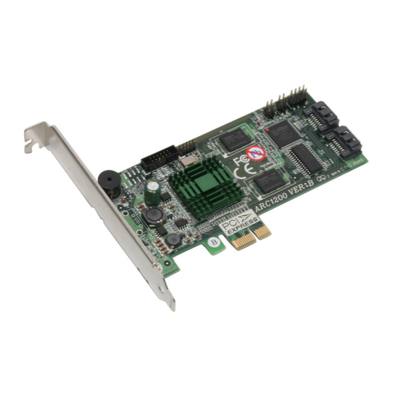
Page 13: Board Layout
HARDWARE INSTALLATION 2.2 Board Layout Follow the instructions below to install a PCIe RAID controller into your PC / Server. Figure 2-1, ARC-1200 (2-port PCIe x1 SATA RAID Controller) Connector Type Description 1.(J6) Reserved 12-pin box header 2.(J1) Reserved 12-pin header 3.(J5) - Page 14 HARDWARE INSTALLATION Tools Required An ESD grounding strap or mat is required. Also required are stan- dard hand tools to open your system’s case. System Requirement The controller can be installed in a universal PCI slot and requires a motherboard that: •...
-
Page 15: Installation
HARDWARE INSTALLATION Warning: High voltages may be found inside computer equipment. Be- fore installing any of the hardware in this package or remov- ing the protective covers of any computer equipment, turn off power switches and disconnect power cords. Do not re- connect the power cords until you have replaced the covers. - Page 16 HARDWARE INSTALLATION card is properly seated in the slot, as shown in Figure 2-2. Next, screw the bracket into the computer chassis. ARC-1200 controller requires a PCIe x1 slot. Figure 2-2, Insert SATA RAID controller into a PCIe x1 slot Step 4.
- Page 17 HARDWARE INSTALLATION Step 5 Connect the SATA Cable ARC-1200 controller has two SATA internal connectors. If you have not yet connected your SATA cables, use the cables included with your kit to connect the controller to the SATA hard drives.
- Page 18 HARDWARE INSTALLATION If the logical level is different between the fist 2 sets of the activity (HDD) LED header (LED attached to Set 1 but not Set 2), the con- troller will assign the first activity LED header as the global indica- tor connector.
- Page 19 HARDWARE INSTALLATION Figure 2-4, ARC-1200 global LED connection for computer case. B: Individual LED Indicator Connector Connect the cables for the drive activity (HDD) LEDs and fault LEDs between the backplane of the cage and the respective con- nector on the SATA RAID controller. The following describes the fault/activity LED.
- Page 20 HARDWARE INSTALLATION Figure 2-5, ARC-1200 Individual LED indica- tors connector, for each channel drive. Step 7. Re-check the SATA HDD LED and Fault LED Cable Connections Be sure that the proper failed drive channel information is dis- played by the fault and activity (HDD) LEDs. An improper con- nection will tell the user to ‘‘Hot Swap’’...
- Page 21 Please refer to the Chapter 4, Driver Installation, for the detailed installation procedure. Note: Look for newest release versions of drivers, please download from http://www.areca.com.tw Step 11. Install ArcHttp Proxy Server The SATA RAID controller firmware has embedded the web-browser McRAID storage manager. ArcHttp proxy server utility will launch it.
- Page 22 HARDWARE INSTALLATION Summary of the Installation The flow chart below describes the installation procedures for SATA RAID controller. These procedures include hardware installa- tion, the creation and configuration of a RAID volume through the McBIOS, OS installation and installation of SATA RAID controller software.
- Page 23 Before launching the SNMP agent in the sever, you need to en- able the fireware-embedded SNMP community configuration first and install Areca SNMP Extension Agent in your server system. If you need additional information about installation and start-up the function, see the SNMP Operation and Installation section in the...
-
Page 24: Mcbios Raid Manager
BIOS CONFIGURATION 3. McBIOS RAID Manager The system mainboard BIOS automatically configures the following SATA RAID controller parameters at power-up: • I/O Port Address • Interrupt Channel (IRQ) • Adapter ROM Base Address Use McBIOS RAID manager to further configure the SATA RAID con- troller to suit your server hardware and operating system. -
Page 25: Mcbios Raid Manager
While the desired adapter is highlighted, press the Enter key to enter the main menu of the McBIOS RAID manager. I/O Port Addr:FD700000h, F2 (Tab): Select Controller, F10: Reset System Areca Technology Corporation RAID Controller Note: Main Menu... -
Page 26: Configuring Raid Sets And Volume Sets
BIOS CONFIGURATION • Add physical drives, • Define volume sets, • Modify volume sets, • Modify RAID level/stripe size, • Define pass-through disk drives and • Modify system functions. 3.3 Configuring Raid Sets and Volume Sets You can configure RAID sets and volume sets with McBIOS RAID manager automatically using “Quick Volume/Raid Setup”... -
Page 27: Using Raid Set/Volume Set Function Method
BIOS CONFIGURATION 3.5 Using RAID Set/Volume Set Function Method In “Raid Set Function”, you can use the “Create Raid Set” function to generate a new RAID set. In “Volume Set Function”, you can use the “Create Volume Set” function to generate an associated volume set and configuration parameters. -
Page 28: Main Menu
The main menu shows all functions that are available for executing actions, which is accomplished by clicking on the appropriate link. I/O Port Addr:FD700000h, F2 (Tab): Select Controller, F10: Reset System Areca Technology Corporation RAID Controller Note: Main Menu The manufacture... -
Page 29: Quick Volume/Raid Setup
4. If you need to add an additional volume set, use the main menu “Create Volume Set” function. I/O Port Addr:FD700000h, F2 (Tab): Select Controller, F10: Reset System Areca Technology Corporation RAID Controller Main Menu Quick Volume/Raid Setup Raid Set Function... - Page 30 This option works on different OS which supports 16 bytes CDB. such as: Windows 2003 with SP1 Linux kernel 2.6.x or latter For more details please download PDF file from ftp://ftp.areca. com.tw/RaidCards/Documents/Manual_Spec/Over2TB_ 050721.zip A single volume set is created and consumes all or a portion of the disk capacity available in this RAID set.
- Page 31 RAID set and volume set will start to initialize it. Select “Foreground Initialization”, “No Initialization” or "No Init (To Rescue Volume)" for initialization. I/O Port Addr:FD700000h, F2 (Tab): Select Controller, F10: Reset System Areca Technology Corporation RAID Controller Main Menu Available Capacity : 140.0GB...
-
Page 32: Raid Set Function
RAID set for the first time or delete existing RAID sets and reconfigure the RAID set. I/O Port Addr:FD700000h, F2 (Tab): Select Controller, F10: Reset System Areca Technology Corporation RAID Controller Main Menu Quick Volume/Raid Setup Raid Set Function... -
Page 33: Delete Raid Set
BIOS CONFIGURATION 3.6.2.2 Delete Raid Set To erase and reconfigure a RAID set completely, you must delete it and re-create the RAID set first. To delete a RAID set, select the RAID set number that user want to delete in the “Se- lect Raid Set to Delete”... -
Page 34: Activate Incomplete Raid Set
BIOS CONFIGURATION 3.6.2.4 Activate Incomplete Raid Set The following screen shows “Raid Set Information” after one of its disk drive was removed in the power off state. When one of the disk drives is removed in power off state, the RAID state will change to “Incomplete State”. -
Page 35: Volume Set Function
2TB because the controller is capable of 64-bit LBA mode. However, the operating system itself may not be capable of addressing more than 2TB. See the Areca website for details. To create a volume set, follow the following steps:... - Page 36 The user can modify the default values in this screen; the modification proce- dures are in section 3.7.3.3. I/O Port Addr:FD700000h, F2 (Tab): Select Controller, F10: Reset System Areca Technology Corporation RAID Controller Available Capacity : 70.0GB Main Menu Selected Capacity : 70.0GB...
-
Page 37: Volume Name
This option uses 16 bytes CDB instead of 10 bytes. The maximum volume capacity up to 512TB. This option works on different OS which supports 16 bytes CDB. such as: Windows 2003 with SP1 Linux kernel 2.6.x or latter For more details please download PDF file from ftp://ftp. areca.com.tw/RaidCards/Documents/Manual_Spec/ Over2TB_050721.zip... -
Page 38: Stripe Size
BIOS CONFIGURATION • Stripe Size This parameter sets the size of the segment written to each disk in a RAID 0 or 1 logical drive. You can set the stripe size to 4 KB, 8 KB, 16 KB, 32 KB, 64 KB, or 128 KB. •... -
Page 39: Modify Volume Set
BIOS CONFIGURATION ter key to show all volume sets within that RAID set. Move the cursor to the volume set number that is to be deleted and press Enter to delete it. 3.6.3.3 Modify Volume Set Use this option to modify volume set attributes. To modify vol- ume set attributes from RAID set system function, move the cursor bar to the “Modify Volume Set”... -
Page 40: Volume Set Migration
Move the cursor bar to the “Physical Drives" function” on the main menu and then press the Enter key to perform the operations listed above. I/O Port Addr:FD700000h, F2 (Tab): Select Controller, F10: Reset System Areca Technology Corporation RAID Controller Main Menu Quick Volume/Raid Setup Physical Drive Information... -
Page 41: View Drive Information
BIOS CONFIGURATION 3.6.4.1 View Drive Information When you choose this option, the physical disks connected to the SATA RAID controller are listed. Move the cursor to the de- sired drive and press Enter key to view drive information. 3.6.4.2 Create Pass-Through Disk A pass-through disk is not controlled by the SATA RAID control- ler firmware and thus cannot be a part of a volume set. -
Page 42: Raid System Function
Move the cursor bar to an item, then press Enter key to select the desired function. I/O Port Addr:FD700000h, F2 (Tab): Select Controller, F10: Reset System Areca Technology Corporation RAID Controller Main Menu Raid System Function Quick Volume/Raid Setup... -
Page 43: Jbod/Raid Function
BIOS CONFIGURATION This feature is used to protect the internal RAID system from unauthorized access. The controller will check the password only when entering the main menu from the initial screen. The sys- tem will automatically go back to the initial screen if it does not receive any command in 5 minutes. -
Page 44: Hdd Read Ahead Cache
BIOS CONFIGURATION sary tracking mechanisms for outstanding and completed por- tions of the workload. The SATA RAID controller allows the user to choose the SATA mode: SATA150, SATA150+NCQ, SATA300, SATA300+NCQ. 3.6.5.7 HDD Read Ahead Cache Allow Read Ahead (Default: Enabled)—When Enabled, the drive’s read ahead cache algorithm is used, providing maximum perfor- mance under most circumstances. -
Page 45: Auto Activate Raid Set
BIOS CONFIGURATION 3.6.5.11 Auto Activate Raid Set When some of the disk drives are removed in power off state or boot up stage, the RAID set state will change to “Incomplete State”. But if a user wants to automatically continue to work while the SATA RAID controller is powered on, then user can set the “Auto Activate Raid Set”... -
Page 46: Clear Events Buffer
BIOS CONFIGURATION events information: Time, Device, Event Type, ElapseTime, and Errors. The RAID system does not have a build-in real time clock. The time information is the relative time from the SATA RAID con- troller while it powered on. 3.6.7 Clear Events Buffer Use this feature to clear the entire events buffer. -
Page 47: Driver Installation
If you do not have the software suite CD disc with the package, contact your local dealer or you can also download the latest ver- sion drivers for Windows 2000/XP/2003/Vista, Linux, FreeBSD, So- laris, Mac and more from the Areca web site at http://www.areca. com.tw... - Page 48 DRIVER INSTALLATION These driver diskettes are intended for use with new operating sys- tem installations. Determine the correct kernel version and identify which diskette images contain drivers for that kernel. If the driver file ends in .img, create the appropriate driver diskette using “dd” utility.
-
Page 49: Driver Installation For Windows
DRIVER INSTALLATION 4.2 Driver Installation for Windows The SATA RAID controller can be used with Microsoft Windows 2000, Windows XP, Windows Server 2003 and Windows Vista. The SATA RAID controllers support SCSI Miniport and StorPort Drivers for Windows Server 2003/Vista. 4.2.1 New Storage Device Drivers in Windows 2003/XP-64/Vista The Storport driver is new to Windows 2003/XP-64/Vista. - Page 50 DRIVER INSTALLATION For details, see Chapter 3 McBIOS RAID Manager. Once a vol- ume set is created and configured, continue with next step to install the operating system. 3. Insert the Windows setup CD and reboot the system to begin the Windows installation.
-
Page 51: Making Volume Sets Available To Windows System
DRIVER INSTALLATION 9. After the installation is completed, reboot the system to load the new drivers / operating system. 10. See Chapter 5 in this manual to customize your RAID vol- ume sets using McRAID storage manager. 4.2.2.2 Making Volume Sets Available to Windows System When you reboot the system, log in as a system administrator. - Page 52 DRIVER INSTALLATION 2. Start the system and then press Tab+F6 to enter the Mc- BIOS manager utility. Use the configuration utility to create the RAID set and volume set. For details, see Chapter 3, McBIOS RAID Manager. Once a volume set is created and configured, continue with installation of the driver.
-
Page 53: Uninstall Controller From Windows 2000/Xp/2003/Vista
DRIVER INSTALLATION 4.2.3.1 Making Volume Sets Available to Windows System When you reboot the system, log in as a system administrator. The following steps show how to make any new disk arrays or independent disks accessible to Windows 2000/XP/2003/Vista. This procedure assumes that the SATA RAID controller hard- ware, driver, and Windows are installed and operational in your system. -
Page 54: Driver Installation For Linux
If you are using a Linux distribution for which there is not a com- piled driver available from Areca, you can copy the source from the SATA software suite CD or download the source from the Areca website and compile a new driver. -
Page 55: Driver Installation For Freebsd
FreeBSD 4.x (4.2 and onwards) and 5.x (5.2 and onwards). To check if a more current version driver is available, please see the Areca web site at http://www.areca.com.tw. Please refer to the “readme.txt” file on the SATA RAID controller software software suite CD or website to make driver diskette and to install driver to the system. -
Page 56: Driver Installation For Unixware 7.1.4
DRIVER INSTALLATION 1. Insert the Areca Mac driver & software CD that came with your Areca SATA RAID Adapter. 2. Double-click on the following file that resides at <CD-ROM>\ packages\MacOS to add the installer on the Finder. a. install_mraid_mac.zip (For Power Mac G5) b. -
Page 57: Archttp Proxy Server Installation
ARCHTTP PROXY SERVER INSTALLATION 5. ArcHttp Proxy Server Installation Overview After hardware installation, the SATA disk drives connected to the SATA RAID controller must be configured and the volume set units initialized before they are ready to use. The user interface for these tasks can be accessed through the built-in configuration and administration utility that resides in the controller’s firmware. -
Page 58: For Windows
ARCHTTP PROXY SERVER INSTALLATION 5.1 For Windows You must have administrative level permissions to install SATA RAID software. This procedure assumes that the SATA RAID hard- ware and Windows are installed and operational in your system. Screen captures in this section are taken from a Windows XP instal- lation. -
Page 59: For Linux
RAID controller software. The ArcHttp proxy server is provided on the software CD delivered with SATA card or download from the www.areca.com.tw. The firmware embedded McRAID storage manager can configure and monitor the SATA RAID controller via ArcHttp proxy server. - Page 60 (1). Insert the SATA RAID controller CD in the CD-ROM drive. (2). Copy <CD-ROM>\PACKAGES\Mac\http directory to local (Ex:/ usr/local/sbin). (1). Download from the www.areca.com.tw or from the email attachment. 2. You must have administrative level permissions to install SATA RAID controller ArcHttp proxy server software. This procedure assumes that the SATA RAID hardware and driver are installed and operational in your system.
-
Page 61: For Freebsd
ARCHTTP PROXY SERVER INSTALLATION Controller [1] Http: New client [9] accepted Controller [1] Http: New Recv 243 bytes Controller [1] Http: Send [174] bytes back to the client (3). If you need the “Cfg Assistant”, please refer to section 5.6 ArcHttp Configuration. -
Page 62: For Mac Os 10.X
5.5 For Mac OS 10.x The ArcHttp proxy server is provided on the software CD delivered with SATA RAID controller or download from the www.areca.com. tw. The firmware embedded McRAID storage manager can config- ure and monitor the SATA RAID controller via ArcHttp proxy server. - Page 63 Ex: RaidController_1 Mail address: Enter the sender email that will be shown in the out- going mail, but don’t type IP to replace domain name. Ex: RaidController_1@areca.com.tw Account: Enter the valid account if your SMTP mail server need au- thentication.
-
Page 64: Snmp Trap Configurations
ARCHTTP PROXY SERVER INSTALLATION Note: Please make sure you have completed mail address before you submit mail configurations. • SNMP Trap Configuration When you open the SNMP configuration page, you will see follow- ing settings: • SNMP Trap Configurations Enter the SNMP Trap IP Address. -
Page 65: Snmp System Configurations
ARCHTTP PROXY SERVER INSTALLATION • SNMP System Configurations About community, please refer to Appendix C of SNMP com- munity name. The system Contact, Name and Location that will be shown in the outgoing SNMP trap. • SNMP Trap Notification Configurations The Community Name should be the same as firmware- embedded SNMP Community. -
Page 66: Web Browser-Based Configuration
WEB BROWSER-BASED CONFIGURATION 6. Web Browser-based Configuration Before using the firmware-based browser McRAID storage manager utility, do the initial setup and installation of this product. If you need to boot up the operating system from a RAID volume set, you must first create a RAID volume by using McBIOS RAID manager. -
Page 67: Start-Up Mcraid Storage Manager From Windows Local Administration
WEB BROWSER-BASED CONFIGURATION • Start-up McRAID Storage Manager from Windows Local Administration Screen captures in this section are taken from a Windows XP installation. If you are running another version of Windows, your screens may look different, but the ArcHttp proxy server instal- lation is essentially the same. -
Page 68: Start-Up Mcraid Storage Manager From Linux/Freebsd/Solaris/Mac Local Administration
WEB BROWSER-BASED CONFIGURATION • Start-up McRAID Storage Manager from Linux/ FreeBSD/Solaris/Mac Local Administration To configure the SATA RAID controller. You need to know its IP address. You can find the IP address assigned by the Archttp proxy server installation:Binding IP:[X.X.X.X] for[Computer IP Address] and controller listen to port for [Port Number]. -
Page 69: Main Menu
WEB BROWSER-BASED CONFIGURATION To display RAID set information, move the mouse cursor to the desired RAId set number, then click it. The RAID set information will display. To display volume set information, move the mouse cursor to the desired volume set number, then click it. The volume set information will display. -
Page 70: Raid Set Functions
"Greater Two TB Volume Support" sub-menu. Greater Than Two TB Volume Choose 64bit LBA option. For more details please download PDF file from ftp://ftp. areca.com.tw/RaidCards/Documents/Manual_Spec/ Over2TB_050721.zip 6.5 Raid Set Functions Use the “Raid Set Function” and “Volume Set Function” if you pre- fer to customize your system. -
Page 71: Create Raid Set
WEB BROWSER-BASED CONFIGURATION 6.5.1 Create Raid Set To create a RAID set, click on the “Create Raid Set” link. A “Se- lect The Drive For RAID Set” screen will be displayed showing the drive(s) connected to the current controller. Click on the selected physical drives within the current RAID set. -
Page 72: Activate Incomplete Raid Set
WEB BROWSER-BASED CONFIGURATION The new additional capacity can be utilized by one or more volume sets. The volume sets associated with this RAID set have chance to modify RAID level or stripe size. Follow the instruction presented in the “Modify Volume Set ” to modify the volume sets; operation system specific utilities may be required to expand operating system partitions. -
Page 73: Rescue Raid Set
WEB BROWSER-BASED CONFIGURATION 6.5.7 Rescue Raid Set When the system is powered off in the RAID set update/creation period, the configueation possibly could disappear due to this ab- normal condition. The “RESCUE” function can recover the missing RAID set information. The RAID controller uses the time as the RAID set signature. -
Page 74: Create Volume Set
2TB because the controller is capable of 64-bit LBA mode. However, the operating system itself may not be capable of addressing more than 2TB. See the Areca website for details. To create a volume set on a RAID set, move the cursor bar to the main menu and click on the “Create Volume Set”. -
Page 75: Initialization Mode
WEB BROWSER-BASED CONFIGURATION For more details please download PDF file from ftp://ftp. areca.com.tw/RaidCards/Documents/Manual_Spec/ Over2TB_050721.zip • Initialization Mode Press Enter key to define Foreground Initialization, No Initialization and No Init (To Rescue Volume). When "Foreground Initialization", the initialization proceeds must be completed before the volume set ready for system accesses. -
Page 76: Tag Queuing
WEB BROWSER-BASED CONFIGURATION • Tag Queuing The “Enabled” option is useful for enhancing overall system performance under multi-tasking operating systems. The Com- mand Tag (Drive Channel) function controls the SCSI com- mand tag queuing support for each drive channel. This function should normally remain enabled. -
Page 77: Volume Set Migration
WEB BROWSER-BASED CONFIGURATION Set” function can support the modification of the last volume capacity attribute. To expand the last volume set capacity , move the cursor bar to the “ Capacity” item and entry the capacity size. When finished the above action, click the “Confirm The Operation”... -
Page 78: Create Pass-Through Disk
WEB BROWSER-BASED CONFIGURATION 6.7.1 Create Pass-Through Disk To create pass-through disk, move the mouse cursor to the main menu and click on the “Create Pass-Through” link. The relative setting function screen appears. A pass-through disk is not con- trolled by the SATA RAID controller firmware, it cannot be a part of a volume set. -
Page 79: Delete Pass-Through Disk
WEB BROWSER-BASED CONFIGURATION 6.7.3 Delete Pass-Through Disk To delete a pass-through drive from the pass-through drive pool, move the mouse cursor bar to the main menus and click the “De- lete Pass Through” link. After you complete the selection, mark the checkbox for “Confirm The Operation”... -
Page 80: System Beeper Setting
WEB BROWSER-BASED CONFIGURATION • System Beeper Setting The “System Beeper Setting” function is used to “Disabled” or “Enabled” the SATA RAID controller alarm tone generator. • Background Task Priority The “background Task Priority” is a relative indication of how much time the controller devotes to a rebuild operation. The SATA RAID controller allows the user to choose the rebuild priority (UltraLow, Low, Normal, High) to balance volume set access and rebuild tasks appropriately. -
Page 81: Stagger Power On
WEB BROWSER-BASED CONFIGURATION • Stagger Power on The SATA RAID controller has included the option for customer to select the disk drives sequentially stagger power up value. The values can be selected from 0.4s to 6s per step which powers up one drive. •... -
Page 82: View Events/Mute Beeper
WEB BROWSER-BASED CONFIGURATION the same capacity for both of these drives so that one could replace the other. Multiples Of 1G: If you have 123 GB drives from different ven- dors; chances are that the capacity varies slightly. For example, one drive might be 123.5 GB, and the other 123.4 GB. -
Page 83: Update Firmware
WEB BROWSER-BASED CONFIGURATION the user can only monitor and configure the SATA RAID controller by providing the correct password. The password is used to protect the SATA RAID controller from unauthorized entry. The controller will check the password only when entering the Main menu from the initial screen. The SATA RAID controller will automatically go back to the initial screen when it does not receive any command in 5 minutes. -
Page 84: System Information
WEB BROWSER-BASED CONFIGURATION 6.9.2 System Information To view the SATA RAID controller’s information, move the mouse cursor to the main menu and click on the “System Information” link. The “RAID Subsystem Information” screen appears. Use this feature to view the SATA RAID controller’s informa- tion. -
Page 85: Upgrading Flash Rom Update Process
In-Band PCIe bus McRAID storage manager. New releases of the firmware are available in the form of a DOS file on the shipped CD or Areca’s web site. The files available at the FTP site for each model contain the following files in each version: ARCXXXXNNNN.BIN Software Binary Code (where “XXXX”... - Page 86 APPENDIX 1. To upgrade the RAID controller firmware, move the mouse cursor to “Upgrade Firmware” link. The “Upgrade The RAID System Firmware” screen appears. 2. Click "Browser". Look in the location to which the firmware upgrade software was downloaded. Select the file name and click “Open”.
-
Page 87: Upgrading Firmware Through Nflash Dos Utility
Utility Areca now offers an alternative means communication for the ARC-1200 SATA RAID controller – Upgrade the all files (BIOS, BOOT, FIRM and MBR0) without necessary system starting up to running the ArcHttp proxy server. The nflash utility program is a DOS application, which runs in the DOS operating system. - Page 88 APPENDIX Note: Areca SAS and SATA ll RAID controller firmware version 1.43 date: Feb 2007 and later has supported the ATA-8 spec for HDD microcode download, allowing customer using nflash DOS utility or web browser to upgrade ATA-8 spec for...
-
Page 89: Snmp Operation & Definition
APPENDIX Appendix B SNMP Operation & Definition Overview The McRAID manager includes a firmware-embedded Simple Net- work Management Protocol (SNMP) agent and SNMP Extension Agent for the SATA RAID controller. An SNMP-based management application (also known as an SNMP manager) can monitor the disk array. - Page 90 APPENDIX MIB Compilation and Definition File creation Before the manager application accesses the SATA RAID controller, it is necessary to integrate the MIB into the management applica- tion’s database of events and status indicator codes. This process is known as compiling the MIB into the application. This process is highly vendor-specific and should be well-covered in the User’s Guide of your SNMP application.
- Page 91 Windows are both installed and operational in your sys- tem. To enable the SNMP agent for Windows, configure Windows for TCP/IP and SNMP services. The Areca SNMP Extension Agent file is ARCSNMP.DLL. Screen captures in this section are taken from a Windows XP instal- lation.
- Page 92 SNMP service first.) 3. Click on the “Setup.exe” file then the welcome screen appears. 4. Click the “Next” button and then the “Ready Install the Pro- gram” screen appears. Follow the on-screen prompts to complete Areca SNMP Extension Agent installation.
- Page 93 APPENDIX 5. A Progress bar appears that measures the progress of the Areca SNMP Extension Agent setup. When this screen complete, you have completed the Areca SNMP Extension Agent setup. 6. After a successful installation, the “Installshield Wizard Com- pleted” dialog box of the installation program is displayed. Click the “Finish”...
- Page 94 APPENDIX SNMP Community Configurations Please refer to the community name in this appendix. SNMP Trap Notification Configurations The "Community Name" should be the same as firmware- embedded SNMP Community. The "SNMP Trap Notification Configruations" include level 1: Serious, level 2: Error, level 3: Warning and level 4: Information.
- Page 95 You must have administrative level permission to install SATA RAID software. This procedure assumes that the SATA RAID hardware and FreeBSD are installed and operational in your system. For the SNMP Extension Agent Installation for FreeBSD procedure please refer to <CD-ROM>\packages\FreeBSD\ SNMP\Readme or download from http://www.areca.com.tw...
-
Page 96: Event Notification Configurations
APPENDIX Appendix C Event Notification Configurations The controller classifies disk array events into four levels depending on their severity. These include level 1: Urgent, level 2: Serious, level 3: Warning and level 4: Information. The level 4 covers notificational events such as initialization of the controller and initiation of the re- building process;... -
Page 97: Volume Event
APPENDIX PassThrough Disk Inform Pass Through Disk Created created PassThrough Disk Inform Pass Through Disk Modified modified PassThrough Disk Inform Pass Through Disk Deleted deleted B. Volume Event Event Level Meaning Action Start Initialize Warning Volume initialization has started Start Rebuilding Warning Volume rebuilding has started Start Migrating... -
Page 98: Raid Set Event
APPENDIX C. RAID Set Event Event Level Meaning Action Create RaidSet Warning New raidset created Delete RaidSet Warning Raidset deleted Expand RaidSet Warning Raidset expanded Rebuild RaidSet Warning Raidset rebuilding RaidSet Urgent Raidset degraded Replace HDD Degraded D. Hardware Monitor Event Event Level Meaning... - Page 99 APPENDIX Telnet Log Serious a Telnet login detected InVT100 Log In Serious a VT100 login detected API Log In Serious a API login detected Lost Rebuilding/ Urgent Some rebuilding/ Reinserted the missing member MigrationLBA migration raidset disk back, controller will continue member disks the incompleted rebuilding/ missing before power...
-
Page 100: Raid Concept
APPENDIX Appendix D RAID Concept RAID Set • A RAID set is a group of disks connected to a RAID control- ler. A RAID set contains one or more volume sets. The RAID set itself does not define the RAID level (RAID 0 and RAID 1); the RAID level is defined within each volume set. -
Page 101: Ease Of Use Features
RAID set. Therefore, if a server fails, the RAID set disk drives can be moved to another server with an Areca RAID controller and the disks can be inserted in any order. • Online Capacity Expansion... - Page 102 APPENDIX the case of disk failure, the volume set transitions from “migrat- ing” state to “migrating+degraded“ state. When the expansion is completed, the volume set would then transition to “degraded” mode. If a global hot spare is present, then it further transitions to the “rebuilding”...
-
Page 103: Online Raid Level And Stripe Size Migration
• Online RAID Level and Stripe Size Migration For those who wish to later upgrade to any RAID capabilities, a system with Areca online RAID level/stripe size migration allows a simplified upgrade to any supported RAID level without having to reinstall the operating system. -
Page 104: High Availability
APPENDIX Windows, NetWare and other advanced operating systems sup- port volume expansion, which enables you to incorporate the additional free space within the volume into the operating sys- tem partition. The operating system partition is extended to incorporate the free space so it can be used by the operating system without creating a new operating system partition. -
Page 105: Adjustable Rebuild Priority
APPENDIX ue as normal, however, the system performance and fault toler- ance will be affected. Adjustable Rebuild Priority • Rebuilding a degraded volume incurs a load on the RAID sub- system. The SATA RAID controllers allow the user to select the rebuild priority to balance volume access and rebuild tasks ap- propriately. -
Page 106: Data Protection
APPENDIX bad sectors without external help using cyclic redundancy check (CRC) checksums stored at the end of each sector. SATA drives perform automatic defect re-assignment for both read and write errors. Writes are always completed - if a location to be written is found to be defective, the drive will automatically relocate that write command to a new location and map out the defective location. -
Page 107: Understanding Raid
APPENDIX Appendix D Understanding RAID RAID is an acronym for Redundant Array of Independent Disks. It is an array of multiple independent hard disk drives that provides high performance and fault tolerance. The SATA RAID control- ler implements several levels of the Berkeley RAID technology. An appropriate RAID level is selected when the volume sets are defined or created. -
Page 108: Raid 1
APPENDIX RAID 1 • RAID 1 is also known as “disk mirroring”; data written on one disk drive is simultaneously written to another disk drive. Read per- formance will be enhanced if the array controller can, in parallel, access both members of a mirrored pair. During writes, there will be a minor performance penalty when compared to writing to a single disk. -
Page 109: Jbod
APPENDIX • JBOD (Just a Bunch Of Disks) A group of hard disks in a RAID control- ler are not set up as any type of RAID configuration. All drives are available to the operating system as an individual disk. JBOD does not provide data redundancy.
Need help?
Do you have a question about the ARC-1200 and is the answer not in the manual?
Questions and answers