Table of Contents
Advertisement
Quick Links
Advertisement
Table of Contents

Subscribe to Our Youtube Channel
Related Manuals for Schrack Seconet VISOCALL IP Staff Terminal ST-TOUCH


Summary of Contents for Schrack Seconet VISOCALL IP Staff Terminal ST-TOUCH
- Page 1 VISO CALL IP Staff Terminal ST-TOUCH User Manual...
- Page 2 Staff Terminal ST-TOUCH User Manual V 2.1 K-HB-023EN...
-
Page 3: Table Of Contents
Table of Contents Table of Contents Foreword ............................5 Overview ............................6 General Information ........................7 3.1 Structure ..................................7 3.2 Screen lock ................................. 8 User interface ..........................9 4.1 Status bar ..................................9 4.2 List tab ..................................10 4.3 Lists ..................................11 4.3.1 Room list ................................ - Page 4 Table of Contents 10 Device placement ......................... 49 11 Cleaning and disinfection ......................49 12 Operation and maintenance ......................49 Staff Terminal ST-TOUCH User Manual V 2.1 K-HB-023EN...
-
Page 5: Foreword
The VISOCALL IP Staff Terminal operating instructions are intended to serve as a reference volume to sup- port you and assume basic knowledge that has been obtained from the VISOCALL IP communications termi- nal operating instructions. Schrack Seconet wishes you every success with the system! K-HB-023EN Staff Terminal ST-TOUCH User Manual V 2.1... -
Page 6: Overview
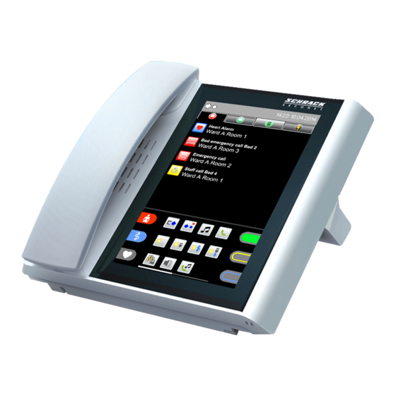
Overview 2 Overview system status list entries handset time and date loudspeaker status bar tab bar lists parting line functions scrollbar microphone Staff Terminal ST-TOUCH User Manual V 2.1 K-HB-023EN... -
Page 7: General Information
General Information Structure 3 General Information The user interface is operated via the touch panel. You navigate through the Staff Terminal software using menus which you open by tapping on icons and buttons. Swipe up or down over the display screen to move through the content of lists with more than 6 list entries. -
Page 8: Screen Lock
General Information Screen lock Screen lock If the touch screen field is not in use, the screen is locked after a predefined time (system configuration). Any entries in the call list or error list are thereafter displayed, and the reminder and attendance list are no longer shown (Fig. -
Page 9: User Interface
User interface Status bar 4 User interface Status bar The status bar constantly shows relevant system states (Fig. 3). Fig. 3 The following states are displayed: Interconnection Manual interconnection A particular ward is connected manually to another. Passive interconnection Another ward is connected to a particular ward. -
Page 10: List Tab
User interface List tab List tab Type of all list tabs Fig. 4 Call list Contains all call events in the entire care area. Reminder list Contains all rooms with a set reminder. Attendance list Contains all rooms with a set attendance. Error list Contains all current malfunctions and faults in the area as well as any third-party systems. -
Page 11: Lists
User interface Lists Lists The list area consists of the tab bar with the 4 list tabs and the list entries at the bottom (Fig. 5). tab bar list tab list entires open tab Fig. 4 Tapping on a list tab opens the respective tab. (Fig. 6a-6d). Call list –... - Page 12 User interface Lists Attendance list – Fig. 6c tab – attendance list entries of the attendance list Ward A Room 2 Ward A Room 3 Fig. 6c Error list – Fig. 6d tab – error list entries of the error list Fault Ward A Room 2 Fault...
-
Page 13: Room List
User interface Room list 4.3.1 Room list Display Tap again on an already selected list tab in the tab bar whether in the call, reminder, attendance or error list (e.g. call list - Fig. 8a). selected list tab tab bar Fig. - Page 14 User interface Room list Room list with care group filter The care group offers the possibility of merging several rooms within a ward (or even across wards) into groups for nurse or service calls. Since the duty room can have nursing groups that are not visible to the particular care area (these are not displayed on this Staff Terminal during a nurse or service call), it is possible to show these care groups.
-
Page 15: Call List
User interface Call list 4.3.2 Call list To display the call list, go to the tab bar and tap on the tab with the icon. The tab for the current calls is opened (Fig. 10). As soon as a call is initiated in the ward, the display automatically changes and the call is shown with details about the room or bed number and the type of call. -
Page 16: Reminder List
User interface Reminder list 4.3.3 Reminder list To display the reminder list, go to the tab bar and tap on the tab with the icon. The tab for the current reminders is opened (Fig. 11). This list is displayed like the room list but only those rooms of the care area are displayed which have activated a reminder. -
Page 17: Attendance List
User interface Attendance list 4.3.4 Attendance list To display the attendance list, go to the tab bar and tap on the tab with the icon. The tab for the current attendances is opened (Fig. 12). This list is displayed like the room list but only those rooms of the care area are displayed which have activated an attendance. -
Page 18: Error List
User interface Error list 4.3.5 Error list To display the error list, go to the tab bar and tap on the tab with the icon. The tab for the current errors is opened (Fig. 13). All malfunctions and faults in the care area are displayed in the error list. The list entry contains the type of error and the local position. -
Page 19: Functional Area
User interface Functional area Functional area The functional area is divided into three areas. To the left or right margin of the display are the attendance or call icons (depending on system configuration). In the middle area are the function icons which can be distributed on several display screen pages (optional). Swipe through the scroll bar on the bottom edge of the display to display content in all windows. -
Page 20: Function Icons
User interface Function icons 4.4.2 Function icons The function icons are displayed in the middle part of the function area and can also be distributed on several dis- play screen pages (see scroll bar). The display of function icons depends on the respective service level. Possible displays in the standard mode (service level 0): Interconnection Activation local centralisation... -
Page 21: Call Display And Reminder
Call display and reminder Call display 5 Call display and reminder Call display As soon as a call is initiated in the ward, the display changes automatically and the call list is opened. The call is shown with details about the room or bed number and the type of call (Fig. 15). If there are several calls simultaneously, the call with the highest priority is always displayed in the topmost position. -
Page 22: Call Query
Call display and reminder Call query Heart alarm Disorientation low battery not queried Bathroom or WC call Disorientation manipulation not required not queried Bathroom or WC emergency Disorientation threat call – not queried not queried Bad call Diagnostic associated disconnection call –... - Page 23 Call display and reminder Call query Voice connection Voice connection is established automatically by tapping on the call list entry. The call volume (speaker/handset) can be changed during a conversation by tapping on the volume bar (Fig. 17). Tapping on the icon ends the voice connection immediately, and the connection is automatically cut after 2 minutes.
-
Page 24: Reminder
Call display and reminder Reminder Reminder This allows the identification of rooms after the call query if there is no answer from the caller, a call without voice connection is present, the busy tone is heard, other calls are queried before searching for the call position or calls to other persons (nurse, service staff or doctor) are transferred selectively. - Page 25 Call display and reminder Reminder The list entry (current call) is removed from the call list and transferred to the reminder list (Fig. 19b). list tab - reminder set for nurse local position Ward A Room 3 (flashing green) Fig.
-
Page 26: Room Overview
Room overview Reminder 6 Room overview After opening the room list (see Chapter 4.3.1) tap on the respective list entry (Fig. 20). tab bar select room service staff present Ward A Room 1 Care group 2 room list entries Ward A Room 2 Care group 3 Ward A Room 3... -
Page 27: Room Features
Room overview Room features Room features The following features can be executed for a room: Assign care group Cancel care group assignment Bed enhancement Voice connection to the room 6.1.1 Assigning care groups The care group offers the possibility of merging certain rooms within a ward (or even across ward) into group for nurse or service calls. - Page 28 Room overview Assigning care groups This care group is assigned to the selected room by tapping on the respective care group in this list (Fig. 23b). local position Ward A Room 1 leaving the list status of the care group Care group 1 selection care group Care group 2...
-
Page 29: Bed Enhancement
Room overview Bed enhancement 6.1.2 Bed enhancement For critically ill or freshly operated patients, for example, the call priority can be set upwards. Using this function bed enhancement can be activated or deactivated for the respective patient‘s bed in the se- lected room. -
Page 30: Voice Connection
Voice connection Voice connection via call query 7 Voice connection A voice connection can be established through a call query or through the room list (active calling of a room or patient terminal) by pressing on a list entry. Hands-free calling Hands-free calling is activated if the handset is placed in the slot provided for it on the Staff Terminal. -
Page 31: Active Voice Connection Via Room List
Voice connection Active voice connection via room list Functions during call query: End voice connection Set reminder nurse Set reminder staff Set reminder doctor Active voice connection via room list Open the room list as described in Chapter 4.3.1. (Fig. 26). tab bar Ward A Room 1 room list entries... -
Page 32: Calling A Room (Communication Terminal)
Voice connection Calling a room (communication terminal) 7.2.1 Calling a room (communication terminal) Tap on the icon in the room overview (see fig. 27). The voice connection is established. (Fig. 28a). monitoring lock activated Monitor lock Ward A Room 2 call volume ending a call Fig. -
Page 33: Calling A Bed Terminal (Patient Terminal)
Voice connection Calling a bed terminal (patient terminal) 7.2.2 Calling a bed terminal (patient terminal) Tap on a bed entry with speaker phone ( icon) in the room overview (see fig. 27). The voice connection is established (Fig. 29a). monitoring lock activated Monitor lock Ward A Room 2... -
Page 34: Functions
Functions Interconnection of words 8 Functions Interconnection of words This allows the formation of care areas, which consist of two or more wards. The indication, call forwarding and query option of every call is then extended in accordance with the priorities set to all ward terminals and commu- nications terminals in this area. -
Page 35: Active Interconnection
Functions Active interconnection 8.1.2 Active interconnection Tap on the icon in the functional area to open the interconnection list. If a particular ward is already interconnected with another ward, all wards that are in the same ward group are dis- played. -
Page 36: Passive Interconnection
Functions Passive interconnection 8.1.3 Passive interconnection If an interconnection to a particular ward was activated from another ward, this is displayed in the status line (Fig. 33a). Tap on the icon in the functional area to open the interconnection list. activate interconnection passive ward interconnection... - Page 37 Functions Passive interconnection Tap on the icon in the menu display of the ward interconnection to activate another interconnection. The interconnection list opens (Fig. 33b). activate interconnection menu display ward interconnection leaving the list Interconnection Ward B Ward C list entries Ward D with ward names...
-
Page 38: Centralization
Functions Centralization Centralization With local centralization all events in your entire ward is more centrally displayed on the Staff Terminal. Call for- warding to the communication terminals is blocked. The displayed icon in the function box depends on the status of local centralization. Tapping on the icon activates local centralization. -
Page 39: Deactivating Centralization
Functions Deactivating centralization 8.2.2 Deactivating centralization status: active centralization Fig. 35a The icon for active centralization is visible in the status bar (Fig. 35a). Tapping on the icon deactivates it (Fig. 35b). deactivate centralization Fig. 35b To prevent an operating error from deactivating centralization, the security question must be confirmed before the deactivation (Fig. -
Page 40: Announcements
Functions Announcements Announcements Announcements can be made either with the handset on the hook through the built-in microphone or through the handset itself. General announcement An announcement is made to all rooms in the care area. Nurse announcement An announcement is made to all rooms in the care area where nurse or service staff attendance was activated. -
Page 41: Telephone
Functions Telephone Telephone 8.4.1 Call setup Tap on the icon in the functional area to open the menu (Fig. 37a). In the active area tap on the number icons to select the respective call numbers. own extension number menu display - telephone active area delete digit call setup... -
Page 42: Answering Telephone Call
Functions Answering telephone call 8.4.2 Answering telephone call During a telephone call the call number and the name are displayed regardless of the telephone system configura- tion (Fig. 38a). The ringtone volume (chapter 9.2 - Settings/Volumes) and type of ringtone (chapter 9.3 - Settings/Ringtone) can be adjusted. -
Page 43: Radio
Functions Radio Radio You can select the radio programs in this menu. In the function area tap on the icon and the list of radio programmes is opened (Fig. 39a). exit menu menu display – radio programs Radio scrollbar for extended displays list entries radio programs functional area... -
Page 44: Settings
Settings Time and date 9 Settings Time and date You can set the time and date in this menu. Tap on the icon in the functional area to open the menu (Fig. 40). (Depending on configuration the icon can also be shown in the expanded display!) menu display –... -
Page 45: Volume
Settings Volume Volume In this menu you can change the volume for the following settings: • Speech volume • Telephone volume • Announcement volume • Ringtone volume • Multimedia volume Tap on the icon in the functional area to open the menu (Fig. 41). (Depending on configuration the icon can also be shown in the expanded display!) exit menu menu display - volume... -
Page 46: Ringtones
Settings Ringtones Ringtones You can adjust the ringtone in this menu. Tap on the icon in the functional area to open the ringtone list (Fig. 42). (Depending on configuration the icon can also be shown in the expanded display!) exit menu menu display - ringtone Ringtone... -
Page 47: Display Setting
Settings Display setting Display setting You can adjust display brightness in this menu. Tap on the icon in the functional area to open the menu (Fig. 43). (Depending on configuration the icon can also be shown in the expanded display!) exit menu menu display - settings Settings... -
Page 48: Service Level
Settings Service level Service level Through this menu you can switch to another service level depending on a predefined password (operation by the system technician). Switch service level Entering a password brings you to another service level. This icon is displayed if standard level 0 is active. - Page 49 Device placement Service level 10 Device placement The Staff Terminal can be installed as a floor-mounted device (2 foot positions for different inclination angles) or as a wall mounting. The foot can be easily pulled out from the terminal‘s rear panel. By a rotation of 180 ° (Fig. 45a) and subsequent reattachment, you can change the standing position and thus the inclination angle of the device (Fig.
- Page 50 Operation and maintenance Service level Notes: Staff Terminal ST-TOUCH User Manual V 2.1 K-HB-023EN...
- Page 51 Operation and maintenance Service level K-HB-023EN Staff Terminal ST-TOUCH User Manual V 2.1...
- Page 52 Operation and maintenance Service level K-HB-023EN Staff Terminal ST-TOUCH User Manual V 2.1...
Need help?
Do you have a question about the VISOCALL IP Staff Terminal ST-TOUCH and is the answer not in the manual?
Questions and answers