Table of Contents
Advertisement
Quick Links
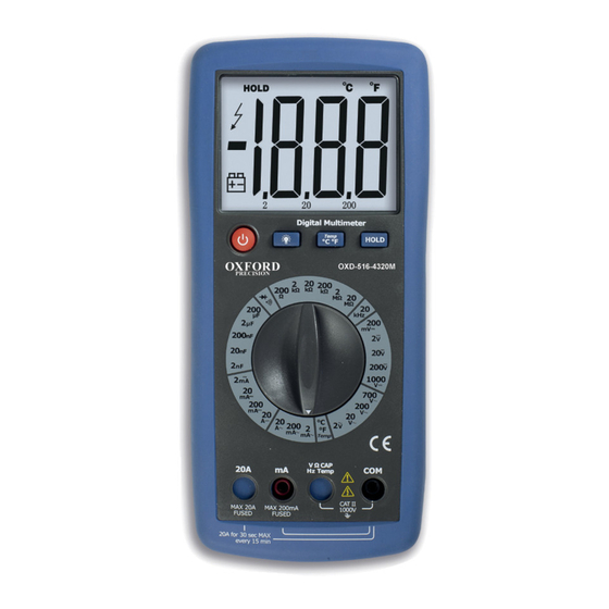
DIGITAL MULTIMETER
• Terminal blocking prevention
• Temperature measurement
• Extra large display
• Hold function
• Backlight
• Tilt stand
• Voltage DC 200mV
• Voltage AC 2V ̴ 700V
• Current DC 2mA ̴ 20A
• Current AC 2mA ̴ 20A
• Resistance 200Ω ̴ 20MΩ
• Capacitance 2nF ̴ 200µF
• Diode test
• Continuity buzzer
• Frequency 20kHz
• CAT II 1000V
• Test Leads
• Temperature Probe
OPERATOR'S MANUAL
ORDER CODE: OXD-516-4320M
CZ
HU
PL
SK
OPERATING INSTRUCTION
̴
1000V
cromwell.co.uk
TH
With mechanical p
— 1 —
— 1 —
Advertisement
Table of Contents

Related Manuals for Oxford PRECISION OXD-516-4320M

Summary of Contents for Oxford PRECISION OXD-516-4320M
- Page 1 • Resistance 200Ω ̴ 20MΩ • Capacitance 2nF ̴ 200µF • Diode test • Continuity buzzer • Frequency 20kHz • CAT II 1000V • Test Leads • Temperature Probe OPERATOR’S MANUAL ORDER CODE: OXD-516-4320M cromwell.co.uk — 1 — — 1 —...
-
Page 2: Safety Information
SAFETY INFORMATION The following safety information must be observed to ensure maximum personal safety during the operation of this meter: • Do not use the meter if the meter or test leads look damaged, or if you suspect that the meter is not operating properly. -
Page 3: Symbols Used
Input Limits This symbol adjacent to one or more terminals identifies them as being associated with ranges Function Maximum Input Input Limits This symbol adjacent to one or more te that may, in normal use, be subjected to V DC or V AC 1000V DC, 700V AC identifies them as being associated with Function... -
Page 4: Specifications
SPECIFICATIONS Insulation: Class2, Double insulation. Over voltage category: CATII - 1000V. Display: 2000 counts LCD display with function indication. Polarity: Automatic, (-) negative polarity indication. Over range: “OL” mark indication. Low battery indication: “BAT” is displayed when the battery voltage drops below the operating level. -
Page 5: Operation
Maximum Input: 1000V dc or 700V ac rms. AC Voltage Range Resolution Accuracy dication. 2.000V +1.0% of rdg + 3 dgts 20.00V 10mV 200.0V 100mV when the 700V +1.2% of rdg + 5 dgts Input Impedance: 10M . 122 o F) at Frequency Range:50 to 400Hz Maximum Input: 1000V dc or 700V ac rms. -
Page 6: Data Hold Button
Sensor: Type K Thermocouple Input Protection: 0.5A/250V Fuse. Diode Test Test current: 1mA typical Open circuit voltage: 2.8V DC typical Overload protection: 250V AC or DC rms. Audible continuity Audible threshold: Less than 50Ω, Test current: <0.3mA Overload protection: 250V AC or DC rms. OPERATION WARNING: Risk of electrocution. -
Page 7: Ac Voltage Measurements
AC VOLTAGE MEASUREMENTS WARNING: Risk of Electrocution. The probe tips may not be long enough to contact the live parts inside some 240V outlets for appliances because the contacts are recessed deep in the outlets. As a result, the reading may show 0 volts when the outlet actually has voltage on it. -
Page 8: Resistance Measurements
RESISTANCE MEASUREMENTS WARNING: To avoid electric shock, disconnect power to the unit under test and discharge all capacitors before taking any resistance measurements. Remove the batteries and unplug the line cords. Set the function switch to the Ω position. Insert the black test lead banana plug into the negative (COM) jack and the red test lead banana plug into the positive Ω... -
Page 9: Temperature Measurements
CAPACITANCE MEASUREMENTS WARNING: To avoid electric shock, disconnect power to the unit under test and discharge all capacitors before taking any capacitance measurements. Remove the batteries and unplug the line cords. Set the function switch to the CAP position. Insert the black test lead banana plug into the negative (-) jack (COM) and the red test lead banana plug into the positive (+) jack (CAP). -
Page 10: Battery Installation
BATTERY INSTALLATION WARNING: To avoid electric shock, disconnect the test leads from any source of voltage before removing the battery door. Disconnect the test leads from the Multimeter. Open the battery cover by loosening the screws using a Phillips head screwdriver. Insert the battery into battery holder, observing the correct polarity. -
Page 11: Replacing The Fuses
REPLACING THE FUSES WARNING: To avoid electric shock, disconnect the test leads from any source of voltage before removing the back cover. Disconnect the test leads from the Multimeter and any item under test. Open the back cover by loosening the screws on the back cover using a Phillips head screwdriver. -
Page 12: Declaration Of Conformity
& specifications. Assuring the quality and performance required by all sectors of industry. OXFORD PRECISION products are fully guaranteed against faulty materials & workmanship. Should they be found to be defective, they will either be repaired or replaced free of charge (fair wear and tear and/or misuse excepted).
Need help?
Do you have a question about the OXD-516-4320M and is the answer not in the manual?
Questions and answers