High Voltage VLF-CM Series Safety, Operation, And Procedure Instructions

High Voltage VLF-CM Series Safety, Operation, And Procedure Instructions

Hide thumbs Also See for VLF-CM Series:

Advertisement

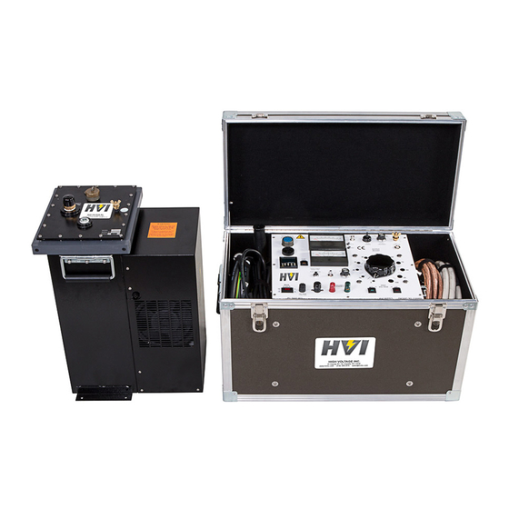
Safety, Operation, and Procedure Instructions for the VLF Series of
AC Hipots
Equipment to be used by trained personnel only
This Operator Manual contains instructions for the operation of a High Voltage power source. The operator of this equipment
must use good judgement and follow all safety precautions noted in this guide to ensure the protection of himself and others in
close proximity to the test area
or death. Proper grounding of the test set must be done prior to
connecting this unit to a power source.
Please Refer to
Documentation
Before Operation
Danger- Lethal Voltages:
. Failure to follow the instructions could result in injury
VLF-CM
Mi n e
SERIES

Advertisement

Table of Contents
loading
Need help?

Need help?

Do you have a question about the VLF-CM Series and is the answer not in the manual?

Questions and answers

Summary of Contents for High Voltage VLF-CM Series

  • Page 1 Equipment to be used by trained personnel only This Operator Manual contains instructions for the operation of a High Voltage power source. The operator of this equipment must use good judgement and follow all safety precautions noted in this guide to ensure the protection of himself and others in .
  • Page 2 VLF Operator Manual  HIGH VOLTAGE, INC. 31 County Route 7A Copake, N.Y. 12516 Phone 518/329-3275 • Fax 518/329-3271 http://www.hvinc.com E-Mail: factory@hvinc.com...
  • Page 3 Instrument Summary This instrument is a Very Low Frequency AC high voltage test system – a VLF hipot. It is an AC hipot whose frequency output is 0.1 Hz or lower, compared to the 50/60 Hz of a conventional AC hipot. The lower the frequency, the lower the current and power it takes to test a capacitive load like a cable.
  • Page 4: Table Of Contents

    T able of Contents About the Operator Manual S E C T I O N 1 General Information Features and Specifications Controls and Indicators 7-10 List of Components S E C T I O N 2 Setting up the Equipment 12,13 Typical VLF Connection Scheme VLF with Cable Reel Connection Scheme...
  • Page 5: About The Operator Manual

    Section 1: Specifications and Controls. Section 2: Setup and Operation. Section 3: Performing Special Operations. The Functions, Features, and Specifications of the VLF Series of AC Hipots are also discussed in the VLF Brochure available from High Voltage, Inc. - 1 -...
  • Page 6: General Information

    VLF Series of Portable AC Hipots manufactured by HIGH VOLTAGE, INC. Features and Specifi c ations The VLF Series of hipot test sets provide true sine wave AC output voltage for the test of high voltage cables and other capacitive loads.
  • Page 7 Red and Black Measuring Leads for Capacitive Load Measurement WARNING DO NOT OPERATE THE VLF HIPOT SET IF THE HIGH VOLTAGE TANK IS 5° OR MORE FROM LEVEL. IF THE UNIT IS OPERATED OUT OF LEVEL, OVERHEATING AND INTERNAL ARCING MAY OCCUR.
  • Page 8 Installation: Category II Pollution: Degree 2 WARNING DO NOT OPERATE THE VLF HIPOT SET IF THE HIGH VOLTAGE TANK IS 5° OR MORE FROM LEVEL. IF THE UNIT IS OPERATED OUT OF LEVEL, OVERHEATING AND INTERNAL ARCING MAY OCCUR. DO NOT STORE OR TRANSPORT VLF HIGH VOLTAGE SECTION ON IT’S SIDE...
  • Page 9 O P E R A T O R M A N U A L Warning! Please refer to documentation before operation Protective Earth Terminal Warning: Hazardous Voltage - 5 -...
  • Page 10 0-100 PEAK MILLIAMPS, /5-0 uF, 5% FS Accuracy Control Case Size 22w x 11d x 15.25 high 26w x 13d x 16 high High Voltage Tank 14.5w x 10.5d x 19 high 15w x 11d x 21.5 high Control Case Weight 50 lbs.
  • Page 11: Controls And Indicators

    O P E R A T O R M A N U A L Table 1 VLF Series Specifications Figure 1 VLF-40 Series front panel controls Figure 2 VLF-60 Series front panel controls - 7 -...
  • Page 12 The OUTPUT control variable transformer adjusts the output voltage. The 0-100 markings on the panel indicate the low to high setting. The control must be at ZERO (0) to energize the high voltage circuits. The output control must always be returned to zero at the completion of testing, prior to de-energizing the output , allow the unit to cycle for 60 seconds to assure full discharge of the load.
  • Page 13 START TIMER pushbutton. The preset time will count down to zero. Upon reaching zero, the timer will sound an alarm indicating the completion of the timing cycle. The timer will not shut down High Voltage. To Reset the timer alarm, with high voltage OFF, depress the START TIMER pushbutton.
  • Page 14 O P E R A T O R M A N U A L The PUSH TO READ X1 pushbutton changes the scale of the CAPACITANCE metering. The modified Wheatstone Bridge incorporated in this circuit indicates x10 readings without depressing the PUSH TO READ X1 pushbutton.
  • Page 15: List Of Components

    Red and Black Measuring Leads for Capacitive Load Measurement WARNING DO NOT OPERATE THE VLF HIPOT SET IF THE HIGH VOLTAGE TANK IS 5° OR MORE FROM LEVEL. IF THE UNIT IS OPERATED OUT OF LEVEL, OVERHEATING AND INTERNAL ARCING MAY OCCUR.
  • Page 16: Setting Up The Equipment

    Place the high voltage tank within 10 ft. of the control on a level area. The cooling and filter assembly of the VLF series will not operate properly if the high voltage tank is placed on uneven ground. A maximum angle for correct operation is 5°.
  • Page 17 Please consult the local codes where applicable or reference the guidelines for grounding found under OPERATING THE EQUIPMENT. WARNING DO NOT OPERATE THE VLF HIPOT SET IF THE HIGH VOLTAGE TANK IS 5° OR MORE FROM LEVEL. IF THE UNIT IS OPERATED OUT OF LEVEL, OVERHEATING AND INTERNAL ARCING MAY OCCUR.
  • Page 18: Typical Vlf Connection Scheme

    O P E R A T O R M A N U A L Operating the Equipment This section provides step-by-step instruction on various test methods. Many facilities have their own in-house test procedures, and this manual is not to supercede these. The purpose of this section is to explain the capabilities of this test set in real-world applications.
  • Page 19: Vlf With Cable Reel Connection Scheme

    AC Testing of High Voltage Cables Ensure that all the steps listed in Setting Up the Equipment have been accomplished. Take special note to ground the control section and the high voltage tank to a solid earth ground. Caution!! Before making any cable connections, ensure that the cable being...
  • Page 20 O P E R A T O R M A N U A L The shields of all cables must be securely tied to ground at the nearest end of the cable. Any conductors or wires in the cable or the vicinity not being tested must be grounded to avoid a buildup of charge and possible shock hazard.
  • Page 21 With the OUTPUT control at zero (zero start interlock engaged), depress the HV ON pushbutton. The HV ON light will glow. At this time the pump and fan on the high voltage section will also energize. If this is the first test at this location, leave the output control at...
  • Page 22 If the test sample fails during the test, the overload circuit will de-energize the high voltage. Should an overload occur, the normal sine wave cycle is interrupted and the load may bleed down much more slowly than when the unit is cycling normally.
  • Page 23 O P E R A T O R M A N U A L WARNING DO NOT OPERATE THE VLF HIPOT SET IF THE HIGH VOLTAGE TANK IS 5° OR MORE FROM LEVEL. IF THE UNIT IS OPERATED OUT OF LEVEL, OVERHEATING AND INTERNAL ARCING MAY OCCUR.
  • Page 24: Vlf Cable Testing Recommendations

    [The High Voltage, Inc. VLF units produce a sine wave output.] The voltage levels (Installation and Acceptance) are based on most used practices worldwide of between 2 and 3Uo for cables rated between 5 and 35 kV.
  • Page 25 For a 0.1 Hz VLF test voltage, the suggested maintenance voltage duration is 15 minutes [7]. ** Data taken from VLF testing performed in Malaysia using High Voltage, Inc. VLF products. [It comes down to engineering compromises. One can test for an hour (which is too long for many users in this country) and catch all defects, or test for 25 –...
  • Page 26: Blank Page For Notes

    O P E R A T O R M A N U A L frequencies. Lower test frequencies are sometimes necessary for testing highly capacitive loads; very long cables. (Most HVI models are powerful enough to allow testing all three phases at once.) - 22 -...
  • Page 27 O P E R A T O R M A N U A L THIS PAGE LEFT BLANK FOR APPLICATION NOTES - 23 -...
  • Page 28: Performing Special Operations

    The VLF SERIES of AC hipots uses precision metal film resistors for measurement and calibration of the voltmeter. The use of these resistors in both the high voltage tank and the metering circuits has minimized circuit drift due to aging and temperature. But, a potentiometer (R4) on the voltmeter PCB can be used to correct for movement changes from the aging of the meter.
  • Page 29: Miscellaneous

    The typical required yearly maintenance items are: 1) Calibration verification. 2) Thorough cleaning of the control and cooling section of the high voltage tank. 3) Replacing the HV insulating oil if necessary. Approximately every 2000 hours of use. 4) Replacing the oil filter if necessary. Approximately every 2000 hours of use.
  • Page 30: Return Material

    M A N U A L RETURNED MATERIAL If for any reason it becomes necessary to return any equipment or materials to High Voltage, Inc., the Service Department of High Voltage, Inc. must be notified, and authorization received, prior to the shipment of the equipment.
  • Page 31: Warranty

    High Voltage. repair by any person, firm or corporation not specifically authorized in writing by High Voltage, or (iii) defects caused by or due to handling by SALE AND DELIVERY. Unless otherwise agreed in writing, sale carrier, or incurred during shipment, transshipment or other move.
  • Page 32 If inspection deemed self-executing, and in the event that either party fails to appear at discloses that the defect is not one for which High Voltage is liable, then any properly noticed arbitration proceeding, an award may be entered Purchaser shall promptly reimburse High Voltage for all expenses incurred.
  • Page 33 Top AC Bucket Truck Tester 600 kVDC @ 5mA HVI Products 10/2015...

Table of Contents