Table of Contents
Advertisement
Quick Links
Safety, Operation, and Procedure Instructions for the VLF Series of
AC Hipots
Equipment to be used by trained personnel only
This Operator Manual contains instructions for the operation of a High Voltage power source. The operator of this equipment
must use good judgement and follow all safety precautions noted in this guide to ensure the protection of himself and others in
close proximity to the test area
or death. Proper grounding of the test set must be done prior to
connecting this unit to a power source.
Please Refer to
Documentation
Before Operation
Danger- Lethal Voltages:
. Failure to follow the instructions could result in injury
VLF-CM
Mi n e
SERIES
Advertisement
Table of Contents

Related Manuals for High Voltage VLF-CM Series


Summary of Contents for High Voltage VLF-CM Series
- Page 1 Equipment to be used by trained personnel only This Operator Manual contains instructions for the operation of a High Voltage power source. The operator of this equipment must use good judgement and follow all safety precautions noted in this guide to ensure the protection of himself and others in .
- Page 2 VLF Operator Manual HIGH VOLTAGE, INC. 31 County Route 7A Copake, N.Y. 12516 Phone 518/329-3275 • Fax 518/329-3271 http://www.hvinc.com E-Mail: factory@hvinc.com...
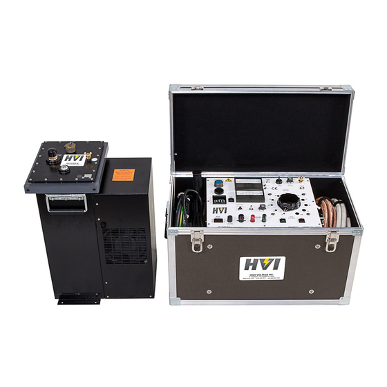
- Page 3 Instrument Summary This instrument is a Very Low Frequency AC high voltage test system – a VLF hipot. It is an AC hipot whose frequency output is 0.1 Hz or lower, compared to the 50/60 Hz of a conventional AC hipot. The lower the frequency, the lower the current and power it takes to test a capacitive load like a cable.
-
Page 4: Table Of Contents
T able of Contents About the Operator Manual S E C T I O N 1 General Information Features and Specifications Controls and Indicators List of Components S E C T I O N 2 Setting up the Equipment 11,12 Typical VLF Connection Scheme VLF with Cable Reel Connection Scheme Operating the Equipment... -
Page 5: About The Operator Manual
Section 1: Specifications and Controls. Section 2: Setup and Operation. Section 3: Performing Special Operations. The Functions, Features, and Specifications of the VLF Series of AC Hipots are also discussed in the VLF Brochure available from High Voltage, Inc. - 1 -... -
Page 6: General Information
General Information This section familiarizes the operator with the features and specifications of the VLF Series of Portable AC Hipots manufactured by HIGH VOLTAGE, INC. Features and Specifications The VLF Series of hipot test sets provide true sine wave AC output voltage for the test of high voltage cables and other capacitive loads. - Page 7 Alligator clip type output connector WARNING DO NOT OPERATE THE VLF HIPOT SET IF THE HIGH VOLTAGE TANK IS 5 OR MORE FROM LEVEL. IF THE UNIT IS OPERATED OUT OF LEVEL, OVERHEATING AND INTERNAL ARCING MAY OCCUR. DO NOT STORE OR TRANSPORT VLF HIGH VOLTAGE SECTION ON IT’S SIDE...
- Page 8 Installation: Category II Pollution: Degree 2 WARNING DO NOT OPERATE THE VLF HIPOT SET IF THE HIGH VOLTAGE TANK IS 5 OR MORE FROM LEVEL. IF THE UNIT IS OPERATED OUT OF LEVEL, OVERHEATING AND INTERNAL ARCING MAY OCCUR. DO NOT STORE OR TRANSPORT VLF HIGH VOLTAGE SECTION ON IT’S SIDE...
- Page 9 O P E R A T O R M A N U A L Safety Symbol Identification Warning! Please refer to documentation before operation Protective Earth Terminal Warning: Hazardous Voltage - 5 -...
-
Page 10: Controls And Indicators
E X T . I N T L K ( E X T E R N A L I N T E R L O C K ) The Ext. Intlk. connector is provided to allow for a normally open safety interlock switch to control the energizing of the high voltage output. - 6 -... - Page 11 The HIGH VOLTAGE ON (OFF) pushbuttons activate (de-activate) the high voltage power circuits. The LED indicators provide long life positive indication of the circuit status. The RED (ON) LED lights when high voltage is energized, the GREEN (OFF) LED lights when the high voltage is de-energized.
- Page 12 The timing function will count up to the preset value. Upon reaching the dwell time, an alarm will sound indicating the need to return the Output Control to zero. Turn off the high voltage, as noted later in the Operating Manual, by allowing the output discharge solenoids and polarity solenoids to cycle at least ten more seconds (one full cycle).
- Page 13 START TIMER pushbutton is depressed. Turn off the high voltage, as noted later in the Operating Manual, by allowing the output discharge solenoids and polarity solenoids to cycle at least 60 more seconds (one full cycle).
-
Page 14: List Of Components
BNC to BNC scope to panel interconnect coax cable WARNING DO NOT OPERATE THE VLF HIPOT SET IF THE HIGH VOLTAGE TANK IS 5 OR MORE FROM LEVEL. IF THE UNIT IS OPERATED OUT OF LEVEL, OVERHEATING AND INTERNAL ARCING MAY OCCUR. -
Page 15: Setting Up The Equipment
Place the high voltage tank within 10 ft. of the control on a level area. The cooling and filter assembly of the VLF series will not operate properly if the high voltage tank is placed on uneven ground. - Page 16 OPERATING THE EQUIPMENT. WARNING DO NOT OPERATE THE VLF HIPOT SET IF THE HIGH VOLTAGE TANK IS 5 OR MORE FROM LEVEL. IF THE UNIT IS OPERATED OUT OF LEVEL, OVERHEATING AND INTERNAL ARCING MAY OCCUR.
-
Page 17: Typical Vlf Connection Scheme
O P E R A T O R M A N U A L Operating the Equipment This section provides step-by-step instruction on various test methods. Many facilities have their own in-house test procedures, and this manual is not to supercede these. The purpose of this section is to explain the capabilities of this test set in real-world applications. -
Page 18: Vlf With Cable Reel Connection Scheme
CABLE AC Testing of High Voltage Cables Ensure that all the steps listed in Setting Up the Equipment have been accomplished. Take special note to ground the control section and the high voltage tank to a solid earth ground. Caution!! - Page 19 O P E R A T O R M A N U A L The shields of all cables must be securely tied to ground at the nearest end of the cable. Any conductors or wires in the cable or the vicinity not being tested must be grounded to avoid a buildup of charge and possible shock hazard.
- Page 20 ON pushbutton. The HV ON light will glow. At this time the pump and fan on the high voltage section will also energize. If this is the first test at this location, leave the output control at zero and allow the pump to circulate oil for 5 minutes prior to raising the output voltage and starting the test.
- Page 21 The limiting factor in the VLF unit is the wave shaping discharge resistors. An excessive capacitance will not fully discharge before the next half cycle starts and causes a discharge at zero crossing through the high voltage circuit. Excessive loads can damage the VLF test set.
- Page 22 O P E R A T O R M A N U A L WARNING DO NOT OPERATE THE VLF HIPOT SET IF THE HIGH VOLTAGE TANK IS 5 OR MORE FROM LEVEL. IF THE UNIT IS OPERATED OUT OF LEVEL, OVERHEATING AND INTERNAL ARCING MAY OCCUR.
-
Page 23: Vlf Cable Testing Recommendations
For an electrical tree to completely penetrate the insulation during the test duration, VLF test voltage levels and testing time durations have been established for the two most commonly used test signals, the cosine-rectangular and the sinusoidal wave shapes. [The High Voltage, Inc. VLF units produce a sine wave output.] The voltage levels (Installation and Acceptance) are based on most used practices worldwide of between 2 and 3Uo for cables rated between 5 and 35 kV. - Page 24 For a 0.1 Hz VLF test voltage, the suggested maintenance voltage duration is 15 minutes [7]. ** Data taken from VLF testing performed in Malaysia using High Voltage, Inc. VLF products. [It comes down to engineering compromises. One can test for an hour (which is too long for many users in this country) and catch all defects, or test for 25 –...
-
Page 25: Blank Page For Notes
O P E R A T O R M A N U A L THIS PAGE LEFT BLANK FOR APPLICATION NOTES - 21 -... -
Page 26: Performing Special Operations
The VLF SERIES of AC hipots uses precision metal film resistors for measurement and calibration of the voltmeter. The use of these resistors in both the high voltage tank and the metering circuits has minimized circuit drift due to aging and temperature. But, a potentiometer (R4) on the voltmeter PCB can be used to correct for movement changes from the aging of the meter. -
Page 27: Miscellaneous
The oil-filled tanks in all the VLF SERIES of hipots are field serviceable. The only requirement is that the tank must be oil filled under vacuum at re-assembly. The parts to service the tank are available from HIGH VOLTAGE, INC. at the address noted on the inside front cover of this manual. -
Page 28: Return Material
SUSPECTED DEFECT: CAUSE OF DEFECT: With the above information provided, High Voltage, Inc. will determine if the return of the equipment is appropriate. If deemed appropriate, a Return Authorization Number will be issued. At that time, the Purchaser will be instructed how to mark and return the equipment. -
Page 29: Warranty
High Voltage. repair by any person, firm or corporation not specifically authorized in writing by High Voltage, or (iii) defects caused by or due to handling by SALE AND DELIVERY. Unless otherwise agreed in writing, sale carrier, or incurred during shipment, transshipment or other move. - Page 30 If inspection deemed self-executing, and in the event that either party fails to appear at discloses that the defect is not one for which High Voltage is liable, then any properly noticed arbitration proceeding, an award may be entered Purchaser shall promptly reimburse High Voltage for all expenses incurred.
- Page 31 Top AC Bucket Truck Tester 600 kVDC @ 5mA HVI Products 10/2015...
Need help?
Do you have a question about the VLF-CM Series and is the answer not in the manual?
Questions and answers